EP1477691B1 - Agencement de palier - Google Patents
Agencement de palier Download PDFInfo
- Publication number
- EP1477691B1 EP1477691B1 EP03009854A EP03009854A EP1477691B1 EP 1477691 B1 EP1477691 B1 EP 1477691B1 EP 03009854 A EP03009854 A EP 03009854A EP 03009854 A EP03009854 A EP 03009854A EP 1477691 B1 EP1477691 B1 EP 1477691B1
- Authority
- EP
- European Patent Office
- Prior art keywords
- bearing
- sleeve
- area
- journal
- drive apparatus
- Prior art date
- Legal status (The legal status is an assumption and is not a legal conclusion. Google has not performed a legal analysis and makes no representation as to the accuracy of the status listed.)
- Expired - Lifetime
Links
- 239000000314 lubricant Substances 0.000 description 3
- 238000005452 bending Methods 0.000 description 2
- 230000005540 biological transmission Effects 0.000 description 1
- 238000011109 contamination Methods 0.000 description 1
- 230000001419 dependent effect Effects 0.000 description 1
- 238000011161 development Methods 0.000 description 1
- 230000018109 developmental process Effects 0.000 description 1
- 230000000694 effects Effects 0.000 description 1
- 239000000463 material Substances 0.000 description 1
- 238000012986 modification Methods 0.000 description 1
- 230000004048 modification Effects 0.000 description 1
- 238000005096 rolling process Methods 0.000 description 1
- 238000000926 separation method Methods 0.000 description 1
Images

Classifications
-
- E—FIXED CONSTRUCTIONS
- E01—CONSTRUCTION OF ROADS, RAILWAYS, OR BRIDGES
- E01C—CONSTRUCTION OF, OR SURFACES FOR, ROADS, SPORTS GROUNDS, OR THE LIKE; MACHINES OR AUXILIARY TOOLS FOR CONSTRUCTION OR REPAIR
- E01C19/00—Machines, tools or auxiliary devices for preparing or distributing paving materials, for working the placed materials, or for forming, consolidating, or finishing the paving
- E01C19/22—Machines, tools or auxiliary devices for preparing or distributing paving materials, for working the placed materials, or for forming, consolidating, or finishing the paving for consolidating or finishing laid-down unset materials
- E01C19/30—Tamping or vibrating apparatus other than rollers ; Devices for ramming individual paving elements
- E01C19/34—Power-driven rammers or tampers, e.g. air-hammer impacted shoes for ramming stone-sett paving; Hand-actuated ramming or tamping machines, e.g. tampers with manually hoisted dropping weight
- E01C19/40—Power-driven rammers or tampers, e.g. air-hammer impacted shoes for ramming stone-sett paving; Hand-actuated ramming or tamping machines, e.g. tampers with manually hoisted dropping weight adapted to impart a smooth finish to the paving, e.g. tamping or vibrating finishers
- E01C19/405—Power-driven rammers or tampers, e.g. air-hammer impacted shoes for ramming stone-sett paving; Hand-actuated ramming or tamping machines, e.g. tampers with manually hoisted dropping weight adapted to impart a smooth finish to the paving, e.g. tamping or vibrating finishers with spreading-out, levelling or smoothing means other than the tamping or vibrating means for compacting or smoothing, e.g. with screws for spreading-out the previously dumped material, with non-vibratory lengthwise reciprocated smoothing beam
-
- F—MECHANICAL ENGINEERING; LIGHTING; HEATING; WEAPONS; BLASTING
- F16—ENGINEERING ELEMENTS AND UNITS; GENERAL MEASURES FOR PRODUCING AND MAINTAINING EFFECTIVE FUNCTIONING OF MACHINES OR INSTALLATIONS; THERMAL INSULATION IN GENERAL
- F16C—SHAFTS; FLEXIBLE SHAFTS; ELEMENTS OR CRANKSHAFT MECHANISMS; ROTARY BODIES OTHER THAN GEARING ELEMENTS; BEARINGS
- F16C19/00—Bearings with rolling contact, for exclusively rotary movement
- F16C19/54—Systems consisting of a plurality of bearings with rolling friction
-
- F—MECHANICAL ENGINEERING; LIGHTING; HEATING; WEAPONS; BLASTING
- F16—ENGINEERING ELEMENTS AND UNITS; GENERAL MEASURES FOR PRODUCING AND MAINTAINING EFFECTIVE FUNCTIONING OF MACHINES OR INSTALLATIONS; THERMAL INSULATION IN GENERAL
- F16C—SHAFTS; FLEXIBLE SHAFTS; ELEMENTS OR CRANKSHAFT MECHANISMS; ROTARY BODIES OTHER THAN GEARING ELEMENTS; BEARINGS
- F16C35/00—Rigid support of bearing units; Housings, e.g. caps, covers
- F16C35/04—Rigid support of bearing units; Housings, e.g. caps, covers in the case of ball or roller bearings
- F16C35/06—Mounting or dismounting of ball or roller bearings; Fixing them onto shaft or in housing
- F16C35/061—Mounting or dismounting of ball or roller bearings; Fixing them onto shaft or in housing mounting a plurality of bearings side by side
-
- F—MECHANICAL ENGINEERING; LIGHTING; HEATING; WEAPONS; BLASTING
- F16—ENGINEERING ELEMENTS AND UNITS; GENERAL MEASURES FOR PRODUCING AND MAINTAINING EFFECTIVE FUNCTIONING OF MACHINES OR INSTALLATIONS; THERMAL INSULATION IN GENERAL
- F16C—SHAFTS; FLEXIBLE SHAFTS; ELEMENTS OR CRANKSHAFT MECHANISMS; ROTARY BODIES OTHER THAN GEARING ELEMENTS; BEARINGS
- F16C35/00—Rigid support of bearing units; Housings, e.g. caps, covers
- F16C35/04—Rigid support of bearing units; Housings, e.g. caps, covers in the case of ball or roller bearings
- F16C35/06—Mounting or dismounting of ball or roller bearings; Fixing them onto shaft or in housing
- F16C35/07—Fixing them on the shaft or housing with interposition of an element
- F16C35/073—Fixing them on the shaft or housing with interposition of an element between shaft and inner race ring
Definitions
- the invention relates to a distribution screw drive storage of a paver.
- the drive storage for augers in road pavers has been carried out so that a bearing pin was passed through a recess in a bearing box (center bearing block), wherein the bearing pin is supported both radially and axially in a bracket in the center bearing block.
- the ends of the journal projecting from the holder on both sides are each provided with a rotary bearing on which drive wheels run.
- these drive bearings for auger are exposed to a high risk of contamination and harsh operating conditions. It is therefore advantageous to make the bearings and the journal interchangeable, so that damaged bearings can be easily replaced.
- each of the journal parts is provided with a bearing for a drive wheel, these two bearing journal parts then both sides into the recess of the bracket to a radial and axial support be plugged into the holder and then connected by screws with each other, which extend parallel to the axial direction of the two bearing journal parts forth in the opposite bearing journal part.
- this design allows replacement of the bearings, however, problems may arise with respect to the strength of the bearing pin.
- the two bearing pin parts can be loaded so that they are no longer aligned axially aligned with each other. This leads to increased wear of the entire storage and in particular also affects the holder in the storage box. If the bracket is damaged, the entire storage box must be removed and replaced or reworked the bracket, which is extremely cumbersome.
- US-A-3 797 612 relates to a drum brake device for a vehicle having first and second brake drums screwed together to form a unit.
- the unit is mounted on a journal having an inner journal and a threaded sleeve with one of the two or four bearings of the drum unit seated on the sleeve.
- the journal is held by the drive shaft radially and axially and in turn serves as a holder for parts of the brake housing.
- the invention is therefore an object of the invention to provide a storage facility in which parts can be easily replaced without any strength problems occur.
- the embodiment of the invention avoids the weak point of the radial separation of the journal, so that it can withstand any bending loads much better. This also makes it possible to expand the augers in different stages or to design the storage completely for long screw shafts, wherein it also allows the inventive design to incorporate special bearings for performance, such as carb or barrel bearings. Also, the storage can be changed later, the old storage box can continue to be used.
- Adapted to different bearings and / or as a wearing part of the bearing pin can be provided according to claim 9 as a spare part.
- Fig. 1 shows a schematic representation of the essential components of a distribution screw 1, as it is used for the transport of bituminous material in the paved road.
- the auger 1 contains the actual auger shaft 2, which in the illustrated embodiment, left and right worm shaft halves, which are each mounted in outer, end-side bearings 3a, 3b, which are designed conventionally, and their inner ends received in a center bearing block 4 in a storage box 5 are that receives the drive for the worm shaft 2.
- the auger 1 is connected in a conventional manner via a frame 6 with the paver.
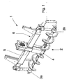
- Fig. 2 shows an axial section through the bearing box 5 at a position at which the two worm shaft halves via drive pins 2a, 2b are mounted in an inventively equipped bearing device 7 with left and right bearing halves A, B in the bearing box 5.
- the storage of the two worm shaft halves is identical except for the details described below, so that initially only the storage of the drive pin 2a of the worm shaft in the left half A bearing to be described.
- the drive pin 2a is fixedly connected to a radial flange 8, which is connected via screws or bolts 9 with a drive wheel 10, which is formed in the present embodiment as a sprocket, which is driven in rotation via a chain 10.
- the drive wheel 10 rests on a shoulder 12 of the radial flange 8 and has with the radial flange 8 an axial contact surface 8a and a radial contact surface 8b.
- a force-transmitting toothing or corrugation 12a is provided between the radial flange 8 and the drive wheel 10, which improves the transmission of power from the drive wheel 10 to the drive pin 2a.
- the radial contact surface 8b is penetrated by the screws 9 and is located within an axial recess 13a of a cover plate 13, which has a central opening 13b through which the drive pin 2a extends, and which is bolted to the bearing box 5 via screws 14.
- the axial recess 13a is provided with lubricant grooves 15 in the form of grooves or grooves and forms a sliding bearing for the radial flange 8 and the drive wheel 10th
- the drive wheel 10 is supported by a bearing 16, which is formed in the illustrated embodiment as a roller bearing, in particular as a roller bearing, on a common for both halves A and B of the bearing device 7 bearing pin 17.
- the journal 17 is divided into two axially and includes a pin body 18 extending through both halves A, B and a sleeve 19.
- the pin body 18 includes a first portion 18a at one end thereof provided with a receiving seat 16a for one of the rolling bearings 16 ,
- the receiving seat 16a is bounded by a radial flange 20 at a distance from the free end of the first region 18a.
- the receiving seat 16a is formed so that the bearing 16 is releasably pushed and held over the shoulder 12 of the adjacent annular flange 8 and one of the usual securing means 21 in place.
- the first region 18a is adjoined by a second region 18b of the journal body 18 whose outer diameter is smaller than the outer diameter of the radial flange 20 and which is provided with an axially extending abutment surface 22.
- This contact surface 22 of the bearing pin 17 is received in a receiving opening 23 a of a holder 23 which is part of the storage box 5 and is firmly connected to the storage box 5.
- the contact surface 22 has a width b which is smaller than the width of the holder 23 in the region of the receiving opening 23a.
- pins 24 extend between the radial flange 20 through the holder 23, which serve as a rotation lock for the bearing pin 17.
- the journal body 18 has a third area 18c, the diameter of which is again reduced in relation to the diameter of the first and second areas 18a, 18b.
- an external thread 25 is provided, onto which the internally threaded sleeve 19 can be screwed.
- the sleeve 19 can be secured in the unscrewed position by suitable measures, such as by hammer blow or the like. against accidental loosening.
- the sleeve 19 has on its outer side in turn a receiving seat 16a for the bearing 16, the lower shell is secured by securing means 21, and whose upper shell is held by the shoulder 12 of the annular flange 8.
- the sleeve 19 contains, on the side facing the holder 23, an annular flange 26 which bears against the holder 23 when the sleeve 19 has been screwed onto the pin body 18. In this way, the bearing pin 17 is supported on the holder 23 via the two annular flanges 20 and 26 in the axial direction and via the contact surfaces 22a and 23a in the radial direction.
- the sleeve 19 continues to act as a clamping device for fixing the bearing pin 17 in the holder 23rd
- the reference numeral 27 lubricant channels are marked, which supply the entire bearing means 7 in a conventional manner with lubricant.
- the halves A and B of the bearing device 7 are formed so that identical parts can be used except for the bearing journal in both bearing halves A, B.
- the assembly of the bearing device 7 according to the invention is carried out in the illustrated embodiment such that first the pin body 18 is mounted with mounted bearing 16 and mounted drive wheel 10 from the left half B through the recess 23a of the holder 23 until the flange 20 abuts the bracket 23 and the rotation over the pins 24 is done. Then, from the side of the left half A, the sleeve 19 is screwed with the bearing 16 mounted thereon and the drive wheel 10 on the pin body 18 until the flange 26 abuts the bracket 23 with a predetermined contact force. This position of the sleeve 19 on the pin body 18 is secured, for example by hammer blow.
- the radial flange 8 is pressed at both bearing halves A, B with the attached drive pin 2a and 2b in the teeth 12a and screwed by the screws 9 on the drive wheel 10. Subsequently, the cover 13 is attached and screwed via the screws 14 to the bearing box 5.
- the sleeve can be connected by other fastening means with the pin body.
- the bearing seats on the sleeve and on the pin body may be formed differently to accommodate different bearings.
- the bearing halves of the bearing device may be formed differently in itself. Bearing and bearing sleeve, possibly with bearings already mounted on it, can be manufactured and delivered as spare or replacement parts.
- the invention is also useful in storage facilities with more than two stores.
Landscapes
- Engineering & Computer Science (AREA)
- General Engineering & Computer Science (AREA)
- Mechanical Engineering (AREA)
- Architecture (AREA)
- Civil Engineering (AREA)
- Structural Engineering (AREA)
- Mounting Of Bearings Or Others (AREA)
- Rolling Contact Bearings (AREA)
Claims (9)
- Dispositif d'entraînement à vis sans fin de distribution d'un finisseur de chaussée, comprenant un dispositif de palier (7) placé dans un logement de palier (5) pour deux roues motrices (10) qui sont placées chacune par l'intermédiaire d'un palier (16) sur un tourillon (17) divisé axialement en deux parties, dans lequel le tourillon (17) présente un corps de tourillon (18) s'étendant d'un seul tenant à travers les deux paliers (16) et un manchon (19) disposé de manière amovible sur le corps de tourillon (18), dans lequel l'un des paliers (16) est placé sur le manchon (19) et l'autre palier (16) sur le corps de tourillon (18), dans lequel le tourillon (17) s'appuie avec le corps de tourillon (18) entre les paliers (16) sur un support (23) du logement de palier (5) radialement et axialement dans les deux directions et est pourvu d'un dispositif anti-rotation (24), et dans lequel le manchon (19) sert de dispositif de fixation pour la fixation du tourillon (17) dans le support (23).
- Dispositif d'entraînement selon la revendication 1, caractérisé en ce que le manchon (19) est vissé sur le corps de tourillon (18).
- Dispositif d'entraînement selon la revendication 1 ou 2, caractérisé en ce que le manchon (19) s'étend jusqu'au support (23) et est pourvu d'une bride de fixation (26) appuyée sur le support (23).
- Dispositif d'entraînement selon l'une quelconque des revendications 1 à 3, caractérisé en ce qu'au moins une roue motrice (10) est reliée de façon amovible à un arbre (2), un assemblage de transmission (9, 12a) étant prévu entre la roue motrice (10) et l'arbre (2).
- Dispositif d'entraînement selon la revendication 4, caractérisé en ce que l'assemblage de transmission comprend un engrenage de transmission (12a).
- Dispositif d'entraînement selon l'une quelconque des revendications 1 à 5, caractérisé en ce que le palier (16) est placé de manière amovible sur le manchon (19).
- Dispositif d'entraînement selon l'une quelconque des revendications 1 à 5, caractérisé en ce que le palier (16) est placé de manière amovible sur le corps de tourillon (18).
- Dispositif d'entraînement selon l'une quelconque des revendications 1 à 7, caractérisé en ce que le corps de tourillon (18) présente, successivement dans le sens axial, un réceptacle (16a) pour l'un des paliers (16), une surface d'appui (22) pour le support (23) et une zone de fixation (25) pour le manchon (19), dont le diamètre est inférieur au diamètre du corps de tourillon (18) dans la zone de la surface d'appui (22).
- Tourillon pour un dispositif d'entraînement selon l'une quelconque des revendications 1 à 8, caractérisé par un corps de tourillon (18) comprenant une première zone (18a) qui est pourvue d'un réceptacle (16a) pour un palier (16), une deuxième zone (18b) qui est pourvue d'une surface d'appui (22) pour un support (23), séparée de la première zone (18a) par une bride annulaire (20), ainsi qu'une troisième zone (18c) au niveau du côté de la surface d'appui (22) opposé à la bride annulaire (20), dans lequel la troisième zone (18c) comprend une zone de fixation (25) pour un manchon (19), le manchon (19) étant pourvu d'un réceptacle (16a) pour un palier (16) et d'une bride de fixation (26).
Priority Applications (2)
| Application Number | Priority Date | Filing Date | Title |
|---|---|---|---|
| EP03009854A EP1477691B1 (fr) | 2003-05-13 | 2003-05-13 | Agencement de palier |
| DE50303191T DE50303191D1 (de) | 2003-05-13 | 2003-05-13 | Lagereinrichtung |
Applications Claiming Priority (1)
| Application Number | Priority Date | Filing Date | Title |
|---|---|---|---|
| EP03009854A EP1477691B1 (fr) | 2003-05-13 | 2003-05-13 | Agencement de palier |
Publications (2)
| Publication Number | Publication Date |
|---|---|
| EP1477691A1 EP1477691A1 (fr) | 2004-11-17 |
| EP1477691B1 true EP1477691B1 (fr) | 2006-05-03 |
Family
ID=33016844
Family Applications (1)
| Application Number | Title | Priority Date | Filing Date |
|---|---|---|---|
| EP03009854A Expired - Lifetime EP1477691B1 (fr) | 2003-05-13 | 2003-05-13 | Agencement de palier |
Country Status (2)
| Country | Link |
|---|---|
| EP (1) | EP1477691B1 (fr) |
| DE (1) | DE50303191D1 (fr) |
Cited By (1)
| Publication number | Priority date | Publication date | Assignee | Title |
|---|---|---|---|---|
| CN106321651A (zh) * | 2015-11-03 | 2017-01-11 | 无锡市三立轴承有限公司 | 锁紧式轴承安装板结构 |
Families Citing this family (1)
| Publication number | Priority date | Publication date | Assignee | Title |
|---|---|---|---|---|
| JP4674589B2 (ja) | 2007-02-05 | 2011-04-20 | ソニー株式会社 | 固体撮像装置および撮像装置 |
Family Cites Families (3)
| Publication number | Priority date | Publication date | Assignee | Title |
|---|---|---|---|---|
| DE548885C (de) * | 1929-04-25 | 1932-04-21 | Fried Krupp Grusonwerk Akt Ges | Lagerung fuer die Walzen von Walzwerken |
| GB1382713A (en) * | 1971-07-13 | 1975-02-05 | Carias A | Brake device for braking a pair of vehicle wheels arranged side- by-side |
| US3795456A (en) * | 1972-07-19 | 1974-03-05 | Rheinstahl Ag | Worm extruder with built-on transmission |
-
2003
- 2003-05-13 EP EP03009854A patent/EP1477691B1/fr not_active Expired - Lifetime
- 2003-05-13 DE DE50303191T patent/DE50303191D1/de not_active Expired - Lifetime
Cited By (1)
| Publication number | Priority date | Publication date | Assignee | Title |
|---|---|---|---|---|
| CN106321651A (zh) * | 2015-11-03 | 2017-01-11 | 无锡市三立轴承有限公司 | 锁紧式轴承安装板结构 |
Also Published As
| Publication number | Publication date |
|---|---|
| DE50303191D1 (de) | 2006-06-08 |
| EP1477691A1 (fr) | 2004-11-17 |
Similar Documents
| Publication | Publication Date | Title |
|---|---|---|
| EP2303611A1 (fr) | Ensemble articulation et/ou palier | |
| DE3990222B4 (de) | Raupenfahrwerk | |
| EP2163496B1 (fr) | Transporteur à rouleaux avec module d'entraînement séparé | |
| WO2015176866A1 (fr) | Mécanisme de direction | |
| EP0571687B1 (fr) | Dispositif pour presser des brides coniques de tuyaux | |
| DE102018108690A1 (de) | Mahlwalze und Walzenpresse | |
| DE10223125A1 (de) | Gleitlager für eine Windenergieanlage | |
| DE2908678A1 (de) | Planetenabtrieb | |
| EP1214158B1 (fr) | Dispositif pour installer et retirer un palier d'un cylindre d'appui | |
| EP1155829A2 (fr) | Elément de cylindre interchangeable dans une unité d'impression électrographique | |
| EP3390250B1 (fr) | Rouleau de roulement, mécanisme à rouleau de roulement, chaîne à maillons et utilisation d'une chaîne à maillons comme chaîne de transport | |
| EP0040808B1 (fr) | Cylindre | |
| EP1477691B1 (fr) | Agencement de palier | |
| DE69810928T2 (de) | Einstellbares distanzstück für lager | |
| DE4211765A1 (de) | Montagevorrichtung fuer die radtraeger-gummilager der fahrzeugrad-raumlenker | |
| EP2676745B1 (fr) | Dispositif de déformation d'une pièce usinée | |
| DE69901267T2 (de) | Sicherheitsverriegelung für ein Rad | |
| EP3180231B1 (fr) | Barre d'accouplement ou de direction pour véhicule | |
| DE3442518A1 (de) | Elastisch nachgiebiges lenkergelenk, insbesondere fuer achslenker von nutzfahrzeugen | |
| EP2886224B1 (fr) | Tête à rouler les filets | |
| DE3417056A1 (de) | Spindelantrieb | |
| DE9315919U1 (de) | Universal Naben-Abzieh- und Montagevorrichtung | |
| DE4227476C1 (en) | Shaft coupling with two connecting flanges and interposed multi-plate assembly - has specially dimensioned screw bolt shaft cylinder sections associated with centring bushes for play-free support. | |
| EP1053103B1 (fr) | Dispositif d'entrainement pour un composant rotatif d'une machine a imprimer | |
| CH687603A5 (de) | Anordnung zum Einstellen des Lagerspiels bei Zylindern von Druckmaschinen. |
Legal Events
| Date | Code | Title | Description |
|---|---|---|---|
| PUAI | Public reference made under article 153(3) epc to a published international application that has entered the european phase |
Free format text: ORIGINAL CODE: 0009012 |
|
| 17P | Request for examination filed |
Effective date: 20040617 |
|
| AK | Designated contracting states |
Kind code of ref document: A1 Designated state(s): AT BE BG CH CY CZ DE DK EE ES FI FR GB GR HU IE IT LI LU MC NL PT RO SE SI SK TR |
|
| AX | Request for extension of the european patent |
Extension state: AL LT LV MK |
|
| GRAP | Despatch of communication of intention to grant a patent |
Free format text: ORIGINAL CODE: EPIDOSNIGR1 |
|
| AKX | Designation fees paid |
Designated state(s): DE |
|
| GRAS | Grant fee paid |
Free format text: ORIGINAL CODE: EPIDOSNIGR3 |
|
| GRAA | (expected) grant |
Free format text: ORIGINAL CODE: 0009210 |
|
| AK | Designated contracting states |
Kind code of ref document: B1 Designated state(s): DE |
|
| REF | Corresponds to: |
Ref document number: 50303191 Country of ref document: DE Date of ref document: 20060608 Kind code of ref document: P |
|
| PLBE | No opposition filed within time limit |
Free format text: ORIGINAL CODE: 0009261 |
|
| STAA | Information on the status of an ep patent application or granted ep patent |
Free format text: STATUS: NO OPPOSITION FILED WITHIN TIME LIMIT |
|
| 26N | No opposition filed |
Effective date: 20070206 |
|
| REG | Reference to a national code |
Ref country code: DE Ref legal event code: R082 Ref document number: 50303191 Country of ref document: DE Representative=s name: GRUENECKER, KINKELDEY, STOCKMAIR & SCHWANHAEUS, DE |
|
| REG | Reference to a national code |
Ref country code: DE Ref legal event code: R081 Ref document number: 50303191 Country of ref document: DE Owner name: JOSEPH VOEGELE AG, DE Free format text: FORMER OWNER: JOSEPH VOEGELE AG, 68163 MANNHEIM, DE Effective date: 20120217 Ref country code: DE Ref legal event code: R082 Ref document number: 50303191 Country of ref document: DE Representative=s name: GRUENECKER, KINKELDEY, STOCKMAIR & SCHWANHAEUS, DE Effective date: 20120217 Ref country code: DE Ref legal event code: R082 Ref document number: 50303191 Country of ref document: DE Representative=s name: GRUENECKER PATENT- UND RECHTSANWAELTE PARTG MB, DE Effective date: 20120217 |
|
| PGFP | Annual fee paid to national office [announced via postgrant information from national office to epo] |
Ref country code: DE Payment date: 20220525 Year of fee payment: 20 |
|
| REG | Reference to a national code |
Ref country code: DE Ref legal event code: R071 Ref document number: 50303191 Country of ref document: DE |