EP1477796A2 - Système pour la mesure de diffusion de rayons-x à petits-angles avec un faisceau vertical pour analyse simplifié d'échantillons liquides - Google Patents
Système pour la mesure de diffusion de rayons-x à petits-angles avec un faisceau vertical pour analyse simplifié d'échantillons liquides Download PDFInfo
- Publication number
- EP1477796A2 EP1477796A2 EP04010240A EP04010240A EP1477796A2 EP 1477796 A2 EP1477796 A2 EP 1477796A2 EP 04010240 A EP04010240 A EP 04010240A EP 04010240 A EP04010240 A EP 04010240A EP 1477796 A2 EP1477796 A2 EP 1477796A2
- Authority
- EP
- European Patent Office
- Prior art keywords
- sample
- ray
- beampath
- detector
- scattered
- Prior art date
- Legal status (The legal status is an assumption and is not a legal conclusion. Google has not performed a legal analysis and makes no representation as to the accuracy of the status listed.)
- Withdrawn
Links
Images

Classifications
-
- G—PHYSICS
- G01—MEASURING; TESTING
- G01N—INVESTIGATING OR ANALYSING MATERIALS BY DETERMINING THEIR CHEMICAL OR PHYSICAL PROPERTIES
- G01N23/00—Investigating or analysing materials by the use of wave or particle radiation, e.g. X-rays or neutrons, not covered by groups G01N3/00 – G01N17/00, G01N21/00 or G01N22/00
- G01N23/20—Investigating or analysing materials by the use of wave or particle radiation, e.g. X-rays or neutrons, not covered by groups G01N3/00 – G01N17/00, G01N21/00 or G01N22/00 by using diffraction of the radiation by the materials, e.g. for investigating crystal structure; by using scattering of the radiation by the materials, e.g. for investigating non-crystalline materials; by using reflection of the radiation by the materials
- G01N23/201—Investigating or analysing materials by the use of wave or particle radiation, e.g. X-rays or neutrons, not covered by groups G01N3/00 – G01N17/00, G01N21/00 or G01N22/00 by using diffraction of the radiation by the materials, e.g. for investigating crystal structure; by using scattering of the radiation by the materials, e.g. for investigating non-crystalline materials; by using reflection of the radiation by the materials by measuring small-angle scattering
-
- G—PHYSICS
- G01—MEASURING; TESTING
- G01N—INVESTIGATING OR ANALYSING MATERIALS BY DETERMINING THEIR CHEMICAL OR PHYSICAL PROPERTIES
- G01N23/00—Investigating or analysing materials by the use of wave or particle radiation, e.g. X-rays or neutrons, not covered by groups G01N3/00 – G01N17/00, G01N21/00 or G01N22/00
- G01N23/20—Investigating or analysing materials by the use of wave or particle radiation, e.g. X-rays or neutrons, not covered by groups G01N3/00 – G01N17/00, G01N21/00 or G01N22/00 by using diffraction of the radiation by the materials, e.g. for investigating crystal structure; by using scattering of the radiation by the materials, e.g. for investigating non-crystalline materials; by using reflection of the radiation by the materials
- G01N23/207—Diffractometry using detectors, e.g. using a probe in a central position and one or more displaceable detectors in circumferential positions
Definitions
- This invention relates generally to the field of x-ray scattering analysis and, more specifically, to small angle x-ray scattering analysis systems.
- Small angle x-ray scattering is a specialized area within the more general field of x-ray scattering analysis. Unlike the more general wide-angle scattering systems, small angle systems measure phenomena that are observed within angles of just a few degrees from the primary x-ray beam. Thus, such systems may be used to provide structural information on the order of approximately one to one hundred nanometers. This allows characterization of a variety of materials that are not measurable using a wide angle system. However, small angle systems must also face a number of additional problems due to the small angle measurements.
- the distance between the sample being examined and the x-ray detector is typically much longer than that of a wide angle system. Because of the small angular deviation from the main x-ray beam, it is necessary to have this additional length to allow adequate resolution at the x-ray detector. This, of course, increases the noise factor of the system, as the scattered x-rays have an increased opportunity to interact with ambient gas molecules. For this reason, small angle systems typically use an evacuated beampath between the sample and the detector to reduce the ambient gas density. In addition, such systems often make use of x-ray collimating apparatus located between the x-ray source and the sample. The collimator helps to reduce the incidence of parasitic capacitance, and the primary beampath within which the collimator is located may also be evacuated to reduce the presence of ambient gas molecules.
- a small angle x-ray scattering system is provided that is oriented in a vertical configuration.
- This configuration is in contrast to the prior art horizontal systems.
- the horizontal systems make it relatively simple to access system components, they suffer from several drawbacks.
- One of these is in the area of liquid samples.
- the liquid samples When a liquid sample is examined in a horizontal small angle scattering system, it is necessary to contain the liquid in some form of vertical container, such as a capillary.
- the liquid samples are typically not homogeneous in thickness in directions parallel to the x-ray beam direction.
- a significant amount of container surface area is encountered by the source x-ray beam, resulting in additional unwanted scattering signals, and the samples are relatively difficult to load and manipulate within the system.
- the x-ray beam of the small angle x-ray scattering apparatus travels along a vertical path.
- the vertical beam may be in either an upward or a downward direction.
- the beam is provided by an x-ray source that outputs the beam in the vertical direction toward a sample support.
- the sample support maintains the sample in a position that intersects the x-ray beam such that the x-ray energy is scattered from the sample along angles close to the vertical direction.
- the scattered x-ray energy is then detected by an x-ray detector that is positioned to detect x-ray energy that is scattered along directions of less than five degrees relative to the vertical direction.
- the front portion of the system may be located in a primary beampath that is isolated from an external environment.
- This primary beampath leads to a sample chamber in which the sample support is located.
- the sample chamber may itself be isolated from the external environment, and may be provided with at least one access port that provides access to the sample from the outside.
- the primary beampath may be evacuated, and the primary beampath and sample chamber separated by a diaphragm that creates a fluid seal to maintain the vacuum.
- the back end of the system, including the detector may be located in a secondary beampath that is also isolated from the external environment.
- the secondary beampath may be evacuated, and may be separated from the sample chamber by a diaphragm.
- the secondary beampath may also extend into the sample chamber to minimize the distance that the scattered x-ray energy must travel through the unevacuated space of the sample chamber.
- X-ray optics 26 which condition the x-rays into desired spectrum and distribution profiles, are typically used in the primary beampath.
- a collimator such as a pinhole collimator, may also be used to collimate the x-ray beam from the x-ray source before it reaches the sample.
- a translation stage that is movable in at least two perpendicular directions may be attached to the sample support to allow positioning of the sample, and the translation stage may be motorized.
- a microscope may also be used that is positioned to view the sample. The microscope may be an optical microscope or may make use of a video camera. Such a video camera system can be used, for example, with a motorized translation stage to allow automatic positioning of the sample.
- a video camera may also be movable, possibly by a motor, between a position in which it has a good view of the sample, but obstructs a path between the sample and detector, and a position in which there is not such obstruction. In this way, the camera may be moved to a good viewing position during positioning of the sample, and then moved out of the way during x-ray scattering.
- a beamstop may also be located in the system between the sample and the detector, and may be positioned to attenuate a portion of the x-ray beam that passes through the sample without being scattered.
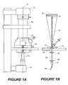
- Figure 1A Shown in Figure 1A is a front view of a small angle x-ray scattering analysis system according to the present invention.
- Figure 1 B shows a more schematic arrangement of the interior components of this system for sake of clarity.
- the same reference numerals are used, respectively, in each of the two figures to indicate common components and thereby allow correspondence between them.
- the system is oriented with the x-ray transmission axis 11 in a vertical orientation with an x-ray source 10 located at the bottom and an x-ray detector 12 at the top.
- x-ray source 10 located at the bottom and an x-ray detector 12 at the top.
- Those skilled in the art will recognize that an alternative configuration could also be used in which the x-ray source 10 was located at the top and the detector at the bottom, while still maintaining the system in a vertical configuration.
- the source 10 is a conventional x-ray source for use with small-angle scattering systems, such as a sealed x-ray tube or a rotating anode generator, with spot focus being preferred.
- x-rays are produced by the bombardment of the target anode with electrons generated from a filament (cathode). The area bombarded by the electrons is called the focal spot on the target, and its size and shape determines the projection of the x-rays from the target.
- the x-rays are projected at a takeoff angle from the anode surface and form what is referred to as the spot focus.
- X-rays generated from a sealed x-ray tube or rotating anode generator consist of white radiation with characteristic radiation wavelengths.
- characteristic radiation wavelengths typically, only one specific characteristic line, usually K ⁇ , is needed. Therefore, since the white radiation produces a high noise background, and unwanted characteristic lines produce extra scattering features scrambled with a desired scattering pattern, these other wavelengths may be eliminated.
- x-ray optics 26 may be provided for this purpose. These optics condition the x-rays into desired spectrum and distribution profiles, and may include a crystal monochromator, capillaries, x-ray filters or an x-ray mirror or mirror group. In the present example, a graded multilayer x-ray mirror (also known as a Göbel Mirror) is used.
- Such mirrors are known in the art.
- a crossed-coupled arrangement of these optics would provide a highly parallel beam that is significantly more intense than can be obtained with the combination of pinhole collimation and a graphite monochromator.
- the multilayer mirrors are located at 26.
- Göbel Mirrors would provide high intensity, due to the relatively small beam size.
- a monochromator may also be used to allow only a selected characteristic line to pass through the primary beampath.
- a monochromator may also be used to allow only a selected characteristic line to pass through the primary beampath.
- the output of the x-ray source is directed toward a sample 14 located on the sample support of an XY translation stage 16.
- the XY translation stage allows the position of the sample to be adjusted in the two dimensions perpendicular to the beam axis.
- An XYZ translation stage may also be used to allow translation in both the XY directions and the Z direction (parallel to the beam axis) as well.
- the x-ray beam undergoes scattering from the sample, the scattered energy being indicated at 18.
- Positioned to receive and detect the scattered x-ray energy is two-dimensional x-ray detector 12, which detects the x-ray energy according to its intensity and position in a two-dimensional plane perpendicular to the beam axis. The portion of the beam that passes through the sample without scattering is blocked or attenuated by beamstop 20.
- the sample 14 resides in a horizontal plane.
- the sample may be placed on a thin sample support, such as a piece of polyester film. If the sample is a liquid, it will spread naturally under the force of gravity, providing a relatively homogeneous thickness across the width of the sample.
- a vertically mounted sample which must be held in a capillary or other similar container, there can be only one additional layer of material through which the source x-ray beam must pass.
- the present embodiment may be viewed as three sections: the primary beampath 22; the sample chamber 24; and the secondary beampath 25. Although such segmentation is not necessary to the invention, it will be discussed as such herein to aid in description.
- a first section is the primary beampath.
- the primary beampath receives the x-ray energy from the source 10 and couples it to an adjacent sample chamber 24. Some form of collimating means are provided along the primary beampath 22.
- a series of pinholes are used, as shown in the schematic drawing of Figure 1 B.
- the beam passes through x-ray optics 26, which condition the x-rays into desired spectrum and distribution profiles. As discussed above, these optics may include components such as a crystal monochromator, capillaries, x-ray filters or an x-ray mirror or mirror group. Such optics are known in the art, and are therefore not discussed herein in any further detail.
- the primary beampath 22 may be evacuated.
- a vacuum port not shown in the figures, may be provided for this purpose.
- the x-ray beam encounters the first pinhole 28 in the series of pinholes used in the primary beampath 22.
- the position of each of the pinholes may be adjusted independently in a direction perpendicular to the x-ray beam to achieve optimal collimation and to remove parasitic scattering.
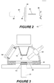
- Figure 2 depicts the operation of a pinhole collimator as used with the present invention. The resolution of the system depends on the resolution of the detector, the distance between the sample and detector, and X-ray beam collimation.
- the collimation system defines the size, shape and divergence of the x-ray beam.
- pinholes may be used to collimate the X-ray beam.
- FIG 2 shows the collimation of the system with pinhole collimator 34, sample 36, beamstop 38 and detector 40.
- the beam 42 that passes undiffracted through the sample, consisting of parallel and divergent components, is attenuated by the beamstop 38, and thereby prevented from significantly impacting on the detection surface.
- R is chosen so that for a lattice spacing smaller than R, the angle between two consecutive orders of Bragg-reflections is larger than ⁇ max .
- the pinhole scattering is defined as the scattering from the pinhole materials, that is, after the 2 nd pinhole 44 shown in Figure 2.
- the region of the pinhole scattering is limited by an anti-scattering pinhole 46, which is the 3 rd pinhole shown in Figure 2.
- the size of the anti-scattering pinhole should be small enough to block as much pinhole scattering as possible, but not so small as to "touch" the primary beam.
- the pinhole scattering observed as a halo around the shadow of the beamstop, is also called as parasitic scattering. If the scattering signal from the sample is much stronger than the parasitic scattering, or if the halo is evenly distributed around the beamstop, the parasitic scattering will not limit the achievable resolution. Some efforts are necessary to reduce the parasitic scattering, such as ensuring a highly parallel beam (for example, by using Göbel cross-coupled mirrors), or using a smaller pinhole size and appropriate pinhole combination.
- the primary x-ray beam After passing through the pinhole collimator, the primary x-ray beam enters the sample chamber 24.
- a schematic view of the sample chamber is shown in Figure 3.
- the primary beampath may be either under a vacuum or filled with a low density gas, such as helium.
- the sample chamber may also be an enclosed space so as to control the environment of the sample.
- the secondary beampath may also be under vacuum or filled with a low-density gas to minimize air scattering. Therefore, the sample chamber may be separated from the primary and secondary beampaths by diaphragms 52 that maintain an airtight separation between them.
- diaphragms may be materials with low x-ray absorption, such as beryllium or Kapton foil.
- the sample chamber may be under an environment different from the primary and secondary beampaths.
- a portion 54 of the secondary beampath extends into the sample chamber so as to reduce the distance that the scattered x-rays must travel in the sample chamber environment.
- the x-ray beam enters the sample chamber and encounters the sample 50 located on the sample support 48.
- An XY translation stage is connected to the sample support, and allows movement of the sample support in the two dimensions perpendicular to the beam direction.
- the translation stage if desired, may also be movable parallel to the beam direction (i.e., may be an XYZ translation stage).
- the translation stage may be motorized, and may be operated manually or automatically. Typically, a stage such as this will have a position accuracy and repeatability in the micron or sub-micron range.
- the sample 50 itself may be supported on a frame, a foil or a nylon net, which is part of the sample support.
- the sample may also be fixed on the support mechanically or glued on a loading cartridge. In general, it is desirable to maintain the sample position on the XY stage while minimizing any x-ray attenuation caused by the support materials.
- the accessory port 58 may be one of a plurality of ports used to provide access or to accommodate measurement devices or sample environment control devices.
- the accessory port 58 shown in Figure 3 may be used for a two-dimensional detector that would allow the system to measure wide angle x-ray scattering (WAXS) as well as the small angle scattering simultaneously.
- WAXS wide angle x-ray scattering
- EDXS energy dispersive x-ray spectroscopy
- optical microscope 60 Also connected to the sample chamber shown in Figure 3 is optical microscope 60.
- the microscope may be used to observe the sample while it is located on the sample support.
- the microscope 60 is particularly useful for positioning of the sample prior to the x-ray scattering analysis. It allows a user to precisely align the sample so as to ensure that the appropriate section of the sample is being examined.
- a video microscope may be used that images the sample for either viewing by a user or input to an automatic positioning system.
- An example of such a video microscope is shown in Figure 4.
- the video camera 62 (which may be magnifying) is movable between two positions, a "camera-on" position and a "camera-off” position.
- the video camera may be mounted on a track and may be movable either manually or automatically.
- a small motor may be used to move the camera between the two positions.
- the camera-on position the camera is located directly above the sample, allowing a good view of the sample that does not suffer from the camera axis being at an angle relative to the x-ray beam axis.
- the secondary beampath is obviously obscured by the camera in the camera-on position, it is moved to the camera-off position before scattering analysis commences.
- the solid line location of the camera indicates the camera-on position, while the dashed lines indicate the position of the camera in the camera-off position. It may be desirable to use the video image in conjunction with an automated sample positioning system that uses sample position information collected by the camera to adjust the XY translation stage to achieve a particular desired sample position.
- the components of the secondary beampath are limited, and are best viewed in Figures 1A and 1B.
- the small-angle scattered x-ray energy 18 from the sample travels through the secondary beampath 25.
- the scattered energy is then incident on two-dimensional detector 12.
- beamstop 20 located in the secondary beampath. Since a portion of the initial x-ray beam passes through the sample without being scattered, it is desirable to inhibit it or attenuate it before it reaches the detector.
- the beamstop 20 may completely block the x-ray beam, or it may attenuate it to an acceptable degree.
- the attenuation may be by virtue of blocking all but a small portion of the x-ray beam, or by reducing the intensity of the beam overall.
- the advantage of this type of beamstop is that it allows the diffraction pattern and a transmission coefficient of the beam to be measured simultaneously at the detector 12.
- the detector 12 may be a high sensitivity, low noise and high resolution two-dimensional detector such as a multiwire proportional counter (MWPC), which is known in the art.
- MWPC multiwire proportional counter
- One example detector has a large imaging area (e.g., 11.5 cm diameter) for x-ray detection, and is sensitive to x-ray energy in a given wavelength range, such as the 3-15 KeV energy range.
- This example detector is a true photon-counting device, with an absolute detection efficiency of eighty percent. It can collect data frames of 1024 x 1024 (or 512 x 512) pixels with a pixel size of 100 ⁇ m (200 ⁇ m for 512 x 512 frames).
- the use of other detectors is also possible, and is well within the ken of one skilled in the art.
- the invention comprises:
Landscapes
- Chemical & Material Sciences (AREA)
- Crystallography & Structural Chemistry (AREA)
- Physics & Mathematics (AREA)
- Health & Medical Sciences (AREA)
- Life Sciences & Earth Sciences (AREA)
- Analytical Chemistry (AREA)
- Biochemistry (AREA)
- General Health & Medical Sciences (AREA)
- General Physics & Mathematics (AREA)
- Immunology (AREA)
- Pathology (AREA)
- Analysing Materials By The Use Of Radiation (AREA)
Applications Claiming Priority (2)
| Application Number | Priority Date | Filing Date | Title |
|---|---|---|---|
| US10/429,926 US6956928B2 (en) | 2003-05-05 | 2003-05-05 | Vertical small angle x-ray scattering system |
| US429926 | 2003-05-05 |
Publications (2)
| Publication Number | Publication Date |
|---|---|
| EP1477796A2 true EP1477796A2 (fr) | 2004-11-17 |
| EP1477796A3 EP1477796A3 (fr) | 2004-12-01 |
Family
ID=33029753
Family Applications (1)
| Application Number | Title | Priority Date | Filing Date |
|---|---|---|---|
| EP04010240A Withdrawn EP1477796A3 (fr) | 2003-05-05 | 2004-04-29 | Système pour la mesure de diffusion de rayons-x à petits-angles avec un faisceau vertical pour analyse simplifié d'échantillons liquides |
Country Status (2)
| Country | Link |
|---|---|
| US (1) | US6956928B2 (fr) |
| EP (1) | EP1477796A3 (fr) |
Cited By (6)
| Publication number | Priority date | Publication date | Assignee | Title |
|---|---|---|---|---|
| US6956928B2 (en) | 2003-05-05 | 2005-10-18 | Bruker Axs, Inc. | Vertical small angle x-ray scattering system |
| US7139366B1 (en) | 2005-05-31 | 2006-11-21 | Osmic, Inc. | Two-dimensional small angle x-ray scattering camera |
| WO2012045846A1 (fr) | 2010-10-08 | 2012-04-12 | Hecus X-Ray Systems Gmbh | Appareil et procédé pour supporter un échantillon liquide pour mesurer la dispersion d'un rayonnement électromagnétique |
| CN102661963A (zh) * | 2012-06-01 | 2012-09-12 | 吉林大学 | 纤维材料专用x射线衍射、散射分析装置 |
| AT511103B1 (de) * | 2011-03-17 | 2012-09-15 | Anton Paar Gmbh | Verfahren und vorrichtung zur untersuchung der röntgenografischen eigenschaften von proben |
| CN103808745A (zh) * | 2014-01-24 | 2014-05-21 | 杭州电子科技大学 | 一种实现小角x射线衍射功能的装置及方法 |
Families Citing this family (19)
| Publication number | Priority date | Publication date | Assignee | Title |
|---|---|---|---|---|
| EP1308716A1 (fr) * | 2001-10-03 | 2003-05-07 | Avantium International B.V. | Méthode et dispositif pour effectuer une analyse en transmission diffraction |
| US8171551B2 (en) * | 2003-04-01 | 2012-05-01 | Mcafee, Inc. | Malware detection using external call characteristics |
| GB0312499D0 (en) * | 2003-05-31 | 2003-07-09 | Council Cent Lab Res Councils | Tomographic energy dispersive diffraction imaging system |
| GB0411401D0 (en) * | 2004-05-21 | 2004-06-23 | Tissuomics Ltd | Penetrating radiation measurements |
| US20060025221A1 (en) * | 2004-07-30 | 2006-02-02 | Jain Nitin D | Networked gaming systems and methods |
| JP4669004B2 (ja) * | 2005-08-29 | 2011-04-13 | 株式会社リガク | 縦横小角x線散乱装置及び小角x線散乱の測定方法 |
| US8184775B1 (en) * | 2010-10-29 | 2012-05-22 | General Electric Company | Dynamic collimator for wide coverage and low dose cardiac CT imaging |
| US10801975B2 (en) | 2012-05-08 | 2020-10-13 | Kla-Tencor Corporation | Metrology tool with combined X-ray and optical scatterometers |
| EP2778665B1 (fr) * | 2013-03-15 | 2019-05-08 | Bruker AXS GmbH | Système d'analyse à rayons x pour l'analyse de diffusion de rayons x |
| CN104833687B (zh) * | 2015-05-06 | 2017-08-18 | 中国工程物理研究院核物理与化学研究所 | 一种用于小角散射实验的热台 |
| JP6999268B2 (ja) * | 2016-01-11 | 2022-01-18 | ブルカー テクノロジーズ リミテッド | X線スキャタロメトリーのための方法および装置 |
| CN106950236B (zh) * | 2017-05-17 | 2023-06-13 | 中国工程物理研究院核物理与化学研究所 | 一种用于中子小角散射谱仪快速定位样品位置的装置 |
| CN106979957B (zh) * | 2017-05-23 | 2023-10-31 | 中国科学院上海应用物理研究所 | 一种利用真空冷热台进行掠入射x射线小角散射实验的方法 |
| US11181489B2 (en) * | 2018-07-31 | 2021-11-23 | Lam Research Corporation | Determining tilt angle in patterned arrays of high aspect-ratio structures by small-angle x-ray scattering |
| FI131496B1 (en) * | 2018-10-19 | 2025-05-23 | Commw Scient Ind Res Org | Energy-dispersive X-ray diffraction analyzer with an improved reflection geometry |
| CN109298004B (zh) * | 2018-12-07 | 2024-10-25 | 深圳市禾苗分析仪器有限公司 | 一种x射线荧光光谱仪 |
| US11022571B2 (en) * | 2019-05-30 | 2021-06-01 | The Boeing Company | X-ray scattering method and system for non-destructively inspecting bond line and porosity |
| CN111665273B (zh) * | 2020-06-17 | 2022-05-17 | 中国科学院长春应用化学研究所 | 一种用于试验机与x射线光源表征联用的高低温环境箱 |
| CN113488222B (zh) * | 2021-06-28 | 2024-05-24 | 散裂中子源科学中心 | 一种中子散射静电悬浮器 |
Family Cites Families (17)
| Publication number | Priority date | Publication date | Assignee | Title |
|---|---|---|---|---|
| DE3406905A1 (de) | 1984-02-25 | 1985-09-05 | Philips Patentverwaltung Gmbh, 2000 Hamburg | Roentgengeraet |
| EP0311177B1 (fr) | 1987-10-05 | 1993-12-15 | Philips Patentverwaltung GmbH | Système pour examiner un corps avec une source de rayonnement |
| US5528646A (en) * | 1992-08-27 | 1996-06-18 | Olympus Optical Co., Ltd. | Sample vessel for X-ray microscopes |
| US5285061A (en) * | 1992-08-28 | 1994-02-08 | Csl Opto-Electronics Corp. | X-ray photocathode for a real time x-ray image intensifier |
| US5589690A (en) * | 1995-03-21 | 1996-12-31 | National Institute Of Standards And Technology | Apparatus and method for monitoring casting process |
| US5982847A (en) * | 1996-10-28 | 1999-11-09 | Utah State University | Compact X-ray fluorescence spectrometer for real-time wear metal analysis of lubrucating oils |
| US6118850A (en) * | 1997-02-28 | 2000-09-12 | Rutgers, The State University | Analysis methods for energy dispersive X-ray diffraction patterns |
| US6175117B1 (en) * | 1998-01-23 | 2001-01-16 | Quanta Vision, Inc. | Tissue analysis apparatus |
| US6442233B1 (en) * | 1998-06-18 | 2002-08-27 | American Science And Engineering, Inc. | Coherent x-ray scatter inspection system with sidescatter and energy-resolved detection |
| EP1120086A4 (fr) * | 1998-09-17 | 2003-05-21 | Quanta Vision Inc | Dispositif pour mammographie a angle reduit et variantes |
| US6163592A (en) * | 1999-01-28 | 2000-12-19 | Bruker Axs, Inc. | Beam scattering measurement system with transmitted beam energy detection |
| US6330301B1 (en) * | 1999-12-17 | 2001-12-11 | Osmic, Inc. | Optical scheme for high flux low-background two-dimensional small angle x-ray scattering |
| KR100382760B1 (ko) * | 2000-09-25 | 2003-05-01 | 삼성전자주식회사 | 엑스선 전자 분광 분석기 |
| JP3666862B2 (ja) * | 2002-06-19 | 2005-06-29 | 株式会社リガク | イオン交換膜の評価方法及び有機物の評価方法 |
| US6751288B1 (en) * | 2002-10-02 | 2004-06-15 | The United States Of America As Represented By The United States Department Of Energy | Small angle x-ray scattering detector |
| DE10317677A1 (de) * | 2003-04-17 | 2004-11-18 | Bruker Axs Gmbh | Primärstrahlfänger |
| US6956928B2 (en) | 2003-05-05 | 2005-10-18 | Bruker Axs, Inc. | Vertical small angle x-ray scattering system |
-
2003
- 2003-05-05 US US10/429,926 patent/US6956928B2/en not_active Expired - Lifetime
-
2004
- 2004-04-29 EP EP04010240A patent/EP1477796A3/fr not_active Withdrawn
Cited By (12)
| Publication number | Priority date | Publication date | Assignee | Title |
|---|---|---|---|---|
| US6956928B2 (en) | 2003-05-05 | 2005-10-18 | Bruker Axs, Inc. | Vertical small angle x-ray scattering system |
| US7139366B1 (en) | 2005-05-31 | 2006-11-21 | Osmic, Inc. | Two-dimensional small angle x-ray scattering camera |
| US7734011B2 (en) | 2005-05-31 | 2010-06-08 | Rigaku Innovative Technologies, Inc. | Two-dimensional small angle x-ray scattering camera |
| US8094780B2 (en) | 2005-05-31 | 2012-01-10 | Rigaku Innovative Technologies, Inc. | Two dimensional small angle X-Ray scattering camera |
| WO2012045846A1 (fr) | 2010-10-08 | 2012-04-12 | Hecus X-Ray Systems Gmbh | Appareil et procédé pour supporter un échantillon liquide pour mesurer la dispersion d'un rayonnement électromagnétique |
| US9164047B2 (en) | 2010-10-08 | 2015-10-20 | Bruker Axs Gmbh | Apparatus and method for supporting a liquid sample for measuring scattering of electromagnetic radiation |
| AT511103B1 (de) * | 2011-03-17 | 2012-09-15 | Anton Paar Gmbh | Verfahren und vorrichtung zur untersuchung der röntgenografischen eigenschaften von proben |
| AT511103A4 (de) * | 2011-03-17 | 2012-09-15 | Anton Paar Gmbh | Verfahren und vorrichtung zur untersuchung der röntgenografischen eigenschaften von proben |
| CN102661963A (zh) * | 2012-06-01 | 2012-09-12 | 吉林大学 | 纤维材料专用x射线衍射、散射分析装置 |
| CN102661963B (zh) * | 2012-06-01 | 2014-02-12 | 吉林大学 | 纤维材料专用x射线衍射、散射分析装置 |
| CN103808745A (zh) * | 2014-01-24 | 2014-05-21 | 杭州电子科技大学 | 一种实现小角x射线衍射功能的装置及方法 |
| CN103808745B (zh) * | 2014-01-24 | 2016-04-06 | 杭州电子科技大学 | 一种实现小角x射线衍射功能的方法 |
Also Published As
| Publication number | Publication date |
|---|---|
| US20040223586A1 (en) | 2004-11-11 |
| US6956928B2 (en) | 2005-10-18 |
| EP1477796A3 (fr) | 2004-12-01 |
Similar Documents
| Publication | Publication Date | Title |
|---|---|---|
| US6956928B2 (en) | Vertical small angle x-ray scattering system | |
| KR102927910B1 (ko) | 투과 x-선 소스를 이용한 고처리량 3D x-선 이미징 시스템 | |
| EP0615123B1 (fr) | Procede et dispositif d'analyse en surface | |
| US8548123B2 (en) | Method and apparatus for using an area X-ray detector as a point detector in an X-ray diffractometer | |
| US5311568A (en) | Optical alignment means utilizing inverse projection of a test pattern/target | |
| JP5116014B2 (ja) | 小角広角x線測定装置 | |
| JP4278108B2 (ja) | 超小角x線散乱測定装置 | |
| CN105008905A (zh) | 光学镜、x射线荧光分析装置以及x射线荧光分析方法 | |
| US20170045465A1 (en) | Apparatus and method for scanning a structure | |
| JPH06258260A (ja) | X線回折装置 | |
| Zhao et al. | Characterization of the eXTP-LAD collimators | |
| US5739542A (en) | X-ray analyzing | |
| US6285736B1 (en) | Method for X-ray micro-diffraction measurement and X-ray micro-diffraction apparatus | |
| EP0697109B1 (fr) | Spectrometre a rayons x presentant un angle de capture rasant | |
| JP3197104B2 (ja) | X線解析装置 | |
| US6935778B2 (en) | Methods and devices for aligning and determining the focusing characteristics of x-ray optics | |
| JP3755034B2 (ja) | 全反射蛍光x線分析法およびその装置 | |
| CN113063808A (zh) | 用于检验至少一个测试物体的检验系统和方法 | |
| Maeda et al. | An x-ray calibration facility with a dynamical pencil beam for the post-Astro-E2 telescopes | |
| WO2024185778A1 (fr) | Dispositif d'imagerie à faisceau de particules et procédé d'imagerie à faisceau de particules | |
| RU2288465C1 (ru) | Устройство для радиографии и томографии | |
| JPH0445552A (ja) | 表面分析装置 | |
| JPS6082840A (ja) | 元素分析方法およびその装置 | |
| JPH0694899A (ja) | 軟x線顕微鏡 |
Legal Events
| Date | Code | Title | Description |
|---|---|---|---|
| PUAI | Public reference made under article 153(3) epc to a published international application that has entered the european phase |
Free format text: ORIGINAL CODE: 0009012 |
|
| PUAL | Search report despatched |
Free format text: ORIGINAL CODE: 0009013 |
|
| AK | Designated contracting states |
Kind code of ref document: A2 Designated state(s): AT BE BG CH CY CZ DE DK EE ES FI FR GB GR HU IE IT LI LU MC NL PL PT RO SE SI SK TR |
|
| AX | Request for extension of the european patent |
Extension state: AL HR LT LV MK |
|
| AK | Designated contracting states |
Kind code of ref document: A3 Designated state(s): AT BE BG CH CY CZ DE DK EE ES FI FR GB GR HU IE IT LI LU MC NL PL PT RO SE SI SK TR |
|
| AX | Request for extension of the european patent |
Extension state: AL HR LT LV MK |
|
| 17P | Request for examination filed |
Effective date: 20050503 |
|
| AKX | Designation fees paid |
Designated state(s): DE GB |
|
| STAA | Information on the status of an ep patent application or granted ep patent |
Free format text: STATUS: THE APPLICATION HAS BEEN WITHDRAWN |
|
| 18W | Application withdrawn |
Effective date: 20150515 |