EP1477875A2 - Dispositif de réglage pour un robinet mélangeur - Google Patents
Dispositif de réglage pour un robinet mélangeur Download PDFInfo
- Publication number
- EP1477875A2 EP1477875A2 EP04010412A EP04010412A EP1477875A2 EP 1477875 A2 EP1477875 A2 EP 1477875A2 EP 04010412 A EP04010412 A EP 04010412A EP 04010412 A EP04010412 A EP 04010412A EP 1477875 A2 EP1477875 A2 EP 1477875A2
- Authority
- EP
- European Patent Office
- Prior art keywords
- neck piece
- thread
- threaded head
- adjusting nut
- adjustment device
- Prior art date
- Legal status (The legal status is an assumption and is not a legal conclusion. Google has not performed a legal analysis and makes no representation as to the accuracy of the status listed.)
- Withdrawn
Links
- XLYOFNOQVPJJNP-UHFFFAOYSA-N water Substances O XLYOFNOQVPJJNP-UHFFFAOYSA-N 0.000 claims description 2
- 241000538562 Banjos Species 0.000 description 3
- 230000007257 malfunction Effects 0.000 description 1
Images

Classifications
-
- G—PHYSICS
- G05—CONTROLLING; REGULATING
- G05D—SYSTEMS FOR CONTROLLING OR REGULATING NON-ELECTRIC VARIABLES
- G05D23/00—Control of temperature
- G05D23/01—Control of temperature without auxiliary power
- G05D23/13—Control of temperature without auxiliary power by varying the mixing ratio of two fluids having different temperatures
- G05D23/1306—Control of temperature without auxiliary power by varying the mixing ratio of two fluids having different temperatures for liquids
- G05D23/132—Control of temperature without auxiliary power by varying the mixing ratio of two fluids having different temperatures for liquids with temperature sensing element
- G05D23/134—Control of temperature without auxiliary power by varying the mixing ratio of two fluids having different temperatures for liquids with temperature sensing element measuring the temperature of mixed fluid
- G05D23/1346—Control of temperature without auxiliary power by varying the mixing ratio of two fluids having different temperatures for liquids with temperature sensing element measuring the temperature of mixed fluid with manual temperature setting means
Definitions
- the invention relates to a setpoint adjustment device on a thermostatically controlled mixing valve for cold and hot water with one rotating on one fixed neck piece arranged on the valve housing, adjusting nut acting on a valve rod, the axially fixed by one on the housing or on the neck piece attached stop ring rotatable on the neck piece is held, the valve stem a portion has the rotationally fixed, but axially displaceable is guided in an opening of the neck piece, wherein the section with a threaded head from the neck piece protrudes axially and with its thread in one appropriate thread engages in the adjusting nut.
- the invention is based on the object in the original term of claim 1 specified setpoint adjustment to improve and in particular to train that by turning the lock nut an inadmissible high axial tensioning of the stop ring is excluded.
- This object is achieved with a generic setpoint device in that the thread and the threaded head are designed such that an axial support of the threaded head on an opposite end face of the neck piece is excluded. This design ensures that no impermissibly high axial forces are generated via the thread in the adjusting nut and conducted into the stop ring. The maximum axial forces that occur are determined by the overload spring in the partial area of the valve rod.
- the support of the threaded head on the end face of the neck piece can be prevented in that the thread of the adjusting nut in the installed position is at a distance from the end face of the neck piece that is greater than the length of the threaded head.
- the distance can expediently be realized with a cylindrical countersink in the adjusting nut.
- Another embodiment of the invention provides that the opening in the neck piece for the valve rod is larger in diameter than the outer diameter of the threaded head, so that the threaded head cannot come into contact with the end face of the neck piece during an axial movement, but axially into the neck piece can immerse.
- the thread in the adjusting nut on the the face of the neck piece facing side from a screw-in banjo bolt can be locked, so that the threaded head axially from the banjo bolt in the Locking nut is secured and no longer on the Front of the neck piece can come to rest. Impermissibly high axial forces can therefore impact the stop ring cannot be transferred.
- the Banjo bolt in a wider area by thread with the adjusting nut after the Threaded head is inserted into the adjusting nut become.
- FIG. 1 shows a valve housing 1 of a thermostatically controlled mixing valve, which is shown in part.
- the valve housing 1 has a lateral opening through which a thermostatically controlled mixing valve known as a structural unit can be introduced.
- a thermostatically controlled mixing valve known as a structural unit can be introduced.
- the opening in the valve housing 1 is closed by a neck piece 2.
- a through opening 21 is formed on a central axis 22, in which a valve rod 3 is arranged, with which the manipulated variable is transmitted to a valve member, not shown in the drawing.
- the valve rod 3 is pressed by a return spring 32 in the direction of an adjusting nut 4.
- the valve rod 3 has a sleeve-shaped section 30 in which an overload device with an overload spring 31 is arranged.
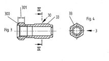
- the partial area 30 of the valve rod is guided in the neck piece 2 with a hexagon 33 in a rotationally fixed but axially displaceable manner and protrudes from the neck piece 2 with a threaded head 300.
- a stop ring 5 is arranged concentrically in a rotationally fixed manner and secured axially in the plug-in position with a locking clip 6.
- the stop ring 5 has on the front side projecting from the valve housing 1 an inwardly directed ring flange 50 which, together with a corresponding outer flange 42 of the adjusting nut, with the interposition of a slide ring 8, forms an axial bearing for the adjusting nut 4.
- a thread 40 is formed which can be brought into engagement with a corresponding thread on the outer jacket of the threaded head 300.
- a toothing 43 is formed on the outer jacket of the adjusting nut 4, on which a grip hood 7 with a corresponding toothing can be pushed on and axially secured in the inserted position with a screw 70.
- the grip hood 7 is thus connected to the adjusting nut 4 in a rotationally fixed manner.
- the threaded head 300 is out of engagement with the thread 40 of the adjusting nut 4, so that in this position the threaded head 300 cannot be pressed against the protruding end face 20 of the neck piece 2 by a rotary movement of the handle cover 7 does not experience any support from the end face 20. It is therefore not possible to direct impermissibly high axial forces onto the stop ring 5, since the thread 40 in the installed position has a distance 9 from the end face 20 which is greater than the length 301 of the threaded head 300. The thread of the threaded head 300 is therefore disengaged from the Adjusting nut 4 arrives, a cylindrical countersink 41 is provided in the adjusting nut, which has a larger diameter than the outer diameter of the threaded head 300.
- the threaded head 300 is pressed by the overload spring 31 and / or the return spring 32 in the direction of the thread 40 of the adjusting nut 4 , It is thus ensured that when the direction of rotation of the handle cover 7 changes, the threaded head 300 is screwed back into the thread 40 of the adjusting nut 4.
- the adjusting nut 4 can also be seen from the front of the outer flange 42 is a continuous cylindrical Have countersink to the start of the thread 40.
Landscapes
- Physics & Mathematics (AREA)
- General Physics & Mathematics (AREA)
- Engineering & Computer Science (AREA)
- Automation & Control Theory (AREA)
- Preventing Unauthorised Actuation Of Valves (AREA)
- Multiple-Way Valves (AREA)
Applications Claiming Priority (2)
| Application Number | Priority Date | Filing Date | Title |
|---|---|---|---|
| DE2003121388 DE10321388A1 (de) | 2003-05-12 | 2003-05-12 | Stellvorrichtung für ein Mischventil |
| DE10321388 | 2003-05-12 |
Publications (2)
| Publication Number | Publication Date |
|---|---|
| EP1477875A2 true EP1477875A2 (fr) | 2004-11-17 |
| EP1477875A3 EP1477875A3 (fr) | 2005-06-29 |
Family
ID=33016361
Family Applications (1)
| Application Number | Title | Priority Date | Filing Date |
|---|---|---|---|
| EP04010412A Withdrawn EP1477875A3 (fr) | 2003-05-12 | 2004-05-03 | Dispositif de réglage pour un robinet mélangeur |
Country Status (2)
| Country | Link |
|---|---|
| EP (1) | EP1477875A3 (fr) |
| DE (1) | DE10321388A1 (fr) |
Citations (1)
| Publication number | Priority date | Publication date | Assignee | Title |
|---|---|---|---|---|
| DE10153988A1 (de) | 2001-11-06 | 2003-05-22 | Grohe Armaturen Friedrich | Stellvorrichtung für ein Mischventil |
Family Cites Families (2)
| Publication number | Priority date | Publication date | Assignee | Title |
|---|---|---|---|---|
| IT1262699B (it) * | 1993-02-09 | 1996-07-04 | Galatron Srl | Valvola miscelatrice di acqua calda e fredda con regolazione termostatica |
| ITMI20011579A1 (it) * | 2001-07-23 | 2003-01-23 | Oscar Nember | Elemento valvolare per la regolazione della miscelazione e della portata in rubinetti e simili |
-
2003
- 2003-05-12 DE DE2003121388 patent/DE10321388A1/de not_active Withdrawn
-
2004
- 2004-05-03 EP EP04010412A patent/EP1477875A3/fr not_active Withdrawn
Patent Citations (1)
| Publication number | Priority date | Publication date | Assignee | Title |
|---|---|---|---|---|
| DE10153988A1 (de) | 2001-11-06 | 2003-05-22 | Grohe Armaturen Friedrich | Stellvorrichtung für ein Mischventil |
Also Published As
| Publication number | Publication date |
|---|---|
| EP1477875A3 (fr) | 2005-06-29 |
| DE10321388A1 (de) | 2004-12-02 |
Similar Documents
| Publication | Publication Date | Title |
|---|---|---|
| DE102012109756B4 (de) | Steigendes Handventil mit Hubbegrenzung | |
| EP3514428B1 (fr) | Levier à main | |
| EP0816730A2 (fr) | Dispositif de limitation de la précontrainte d'un ressort de réglage | |
| DE1924878B2 (de) | Warm- und kaltwasser-mischventil mit relativ zueinander verstellbaren verschlusskoerpern der zuflussventile | |
| DE19936951A1 (de) | Verstellpropeller für Sportboote und Sportjachten | |
| DE2124485C3 (de) | Hubventil für Schweiß- und Schneidbrenner | |
| DE3322179C1 (de) | Einrichtung zur Verriegelung einer vorgewaehlten Spindel-Hubstellung einer Absperrarmatur | |
| EP1477875A2 (fr) | Dispositif de réglage pour un robinet mélangeur | |
| DE10030699C2 (de) | Voreinstellbares Einbauventil | |
| DE69205974T2 (de) | Vorrichtung zum abwechselnden steuern von zwei zusammenwirkenden ventilen, insbesondere von sicherheitsventilen an druckkesseln. | |
| DE202004002987U1 (de) | Druckluft-Wartungsvorrichtung | |
| EP1621951B1 (fr) | Mitigeur avec dispositif d'actionnement | |
| DE700250C (de) | Sicherheitseinrichtung fuer von Hand gesteuerte Ventile | |
| DE1162655B (de) | Schnellschlussventil | |
| DE2252395C3 (de) | Umschalter für ein System Wanne-Brause | |
| DE908964C (de) | Gashahn | |
| DE3340166C2 (fr) | ||
| DE3325715C2 (fr) | ||
| DE964651C (de) | Gasflaschenventil mit Niederschraubventil fuer Fluessiggas mit hohem Butangehalt | |
| DE1291302B (de) | Gasbrennerventil | |
| DE2924372C3 (de) | Ventil, insbesondere thermostatisch gesteuertes Heizkörperventil mit Voreinstellung | |
| DE10236572A1 (de) | Griffbefestigung bei Sanitärarmaturen | |
| DE496549C (de) | Gashahn, insbesondere fuer Gaskocher | |
| DE1550091C (de) | Membrangesteuertes Druckminderven til | |
| DE1219751B (de) | Absperrorgan, insbesondere fuer Rohrleitungen |
Legal Events
| Date | Code | Title | Description |
|---|---|---|---|
| PUAI | Public reference made under article 153(3) epc to a published international application that has entered the european phase |
Free format text: ORIGINAL CODE: 0009012 |
|
| AK | Designated contracting states |
Kind code of ref document: A2 Designated state(s): AT BE BG CH CY CZ DE DK EE ES FI FR GB GR HU IE IT LI LU MC NL PL PT RO SE SI SK TR |
|
| AX | Request for extension of the european patent |
Extension state: AL HR LT LV MK |
|
| PUAL | Search report despatched |
Free format text: ORIGINAL CODE: 0009013 |
|
| AK | Designated contracting states |
Kind code of ref document: A3 Designated state(s): AT BE BG CH CY CZ DE DK EE ES FI FR GB GR HU IE IT LI LU MC NL PL PT RO SE SI SK TR |
|
| AX | Request for extension of the european patent |
Extension state: AL HR LT LV MK |
|
| AKX | Designation fees paid | ||
| RAP1 | Party data changed (applicant data changed or rights of an application transferred) |
Owner name: GROHE AG |
|
| REG | Reference to a national code |
Ref country code: DE Ref legal event code: 8566 |
|
| STAA | Information on the status of an ep patent application or granted ep patent |
Free format text: STATUS: THE APPLICATION IS DEEMED TO BE WITHDRAWN |
|
| 18D | Application deemed to be withdrawn |
Effective date: 20051230 |