EP1477992A1 - Strahlenschutzvorrichtung mit transparenter Strahlenschutzscheibe - Google Patents
Strahlenschutzvorrichtung mit transparenter Strahlenschutzscheibe Download PDFInfo
- Publication number
- EP1477992A1 EP1477992A1 EP04007089A EP04007089A EP1477992A1 EP 1477992 A1 EP1477992 A1 EP 1477992A1 EP 04007089 A EP04007089 A EP 04007089A EP 04007089 A EP04007089 A EP 04007089A EP 1477992 A1 EP1477992 A1 EP 1477992A1
- Authority
- EP
- European Patent Office
- Prior art keywords
- radiation protection
- protection device
- radiation
- screen
- strips
- Prior art date
- Legal status (The legal status is an assumption and is not a legal conclusion. Google has not performed a legal analysis and makes no representation as to the accuracy of the status listed.)
- Granted
Links
Images



Classifications
-
- A—HUMAN NECESSITIES
- A61—MEDICAL OR VETERINARY SCIENCE; HYGIENE
- A61B—DIAGNOSIS; SURGERY; IDENTIFICATION
- A61B6/00—Apparatus or devices for radiation diagnosis; Apparatus or devices for radiation diagnosis combined with radiation therapy equipment
- A61B6/10—Safety means specially adapted therefor
- A61B6/107—Protection against radiation, e.g. shielding
-
- G—PHYSICS
- G21—NUCLEAR PHYSICS; NUCLEAR ENGINEERING
- G21F—PROTECTION AGAINST X-RADIATION, GAMMA RADIATION, CORPUSCULAR RADIATION OR PARTICLE BOMBARDMENT; TREATING RADIOACTIVELY CONTAMINATED MATERIAL; DECONTAMINATION ARRANGEMENTS THEREFOR
- G21F3/00—Shielding characterised by its physical form, e.g. granules, or shape of the material
Definitions
- the invention relates to a radiation protection device, in particular a radiation protection device for shielding the one emitted by an X-ray source X-rays, with a transparent Radiation protection panel according to claim 1.
- a radiation protection chair is known from DE 196 43 623 A1 known, in which a transparent, radiation-absorbing disc and a standing seat aid are linked to a unit.
- the disc is adjustable in height and has indentations as openings on.
- the radiation protection chair is equipped with wheels and can be shifted relative to the examination field become.
- a disadvantage of the known from DE 196 43 623 A1 Radiation protection device is in particular that the Person using the radiation protection chair, for example a Doctor, assistant or nurse, conditionally due to the sitting position in a relatively large Distance to the protective disk. This is on the one hand, the person's freedom of movement is strong limited because the upper extremities are not wide enough can be extended beyond the pane level. On the other hand, the risk of radiation exposure is through the large distance to the disc u. U. increased because the Person to access devices, control switches etc. can, unintentionally from protecting the pane bend out and thereby expose yourself to radiation could.
- the object of the invention is therefore a To create radiation protection device that the required protection against radiation, especially against X-rays, guaranteed sufficient Offers freedom of movement and at the same time in a simple manner carried for use in the operational area and can be arranged arbitrarily.
- the object is achieved by an inventive Radiation protection device with the features of claim 1 solved.
- the radiation protection device is advantageous with a transparent radiation shield z. B. from Provide lead acrylic, which is fixed to a stand device is.
- the radiation protection screen is curved and in standing posture of the user close to the body.
- the radiation shield in in a simple manner on at least one, preferably two, Last is fixed, which on a double cross-shaped foot are fixed.
- the strips either extend in the middle or along the outer edges of the radiation shield parallel to this and are for example by means of screws or similar devices connected to it.
- Another advantage is that the arms of the foot can be of different lengths to the To reduce the risk of the radiation protection device tipping over.
- Rollers attached to the arms allow easy and rapid displacement of the radiation protection device with little effort.
- the radiation protection device can be provided with a height adjustment. This can by means of gas pressure springs or also mechanically, hydraulically or be electrically operated.
- asymmetrical Recesses can be provided in the radiation protection pane, which is the reaching through of the radiation protection screen enable and thus a larger radius of action and more Allow freedom of movement.
- the recesses if necessary can be covered by lead rags in a suitable manner Way such. B. by means of strips, snaps or Velcro strips to be fixed to the radiation protection screen can.
- a lead apron at the bottom of the radiation shield which can consist of several apron parts advantageously the lower extremities of the user Protect close to the ground. This can also be done using Lasts, snaps or Velcro on the Radiation protection screen must be fixed.
- the attachment of foldable handles is on the radiation protection screen is advantageous, which makes the Moving the radiation protection device easy and can be carried out tip-over and no hand and Leave fingerprints on the radiation shield become.
- the use of a base connected to the foot to guide the radiation shield is advantageous because on the one hand the radiation shield Damage can be protected using Radiation protection material protecting the lower extremities of the user and any height adjustment can be easily integrated into the base.
- Fig. 1 shows a schematic, perspective Representation of a first embodiment of a Radiation protection device according to the invention 1.
- Die Radiation protection device 1 according to the invention is suitable for Shielding of an X-ray source in particular radiated radiation, e.g. in medical Area, particularly in the radiologically based Endoscopy.
- the invention Radiation protection device 1 is, however, also suitable for other use cases.
- Radiation protection device 1 comprises a Radiation protection panel 2, which preferably consists of a There is lead alloy acrylic glass, and a stand device 3, on which the radiation shield 2 is mounted.
- the radiation protection pane 2 can, as in the present case first embodiment shown, fixed for example connected to the stand device 3 by means of screws 4 his.
- the radiation shield 2 is preferably curved formed around which the radiation protection device 1 optimal protection against radiation guarantee.
- the radiation shield 2 has one Radius of curvature, which is normal to that of a dimensioned human body. Thereby can the person using the radiation protection device 1 get very close to the radiation protection device 1 and has an optimal radius of action.
- Recesses 5 are in the radiation protection pane 2 provided which serve as passages. These are like that arranged that they are approximately at the level of the elbow joints the person using the radiation protection device 1 are so that the forearms through the recesses 5th Access to instruments, control levers and. received without that the person using the radiation protection device 1 reach around the radiation shield 2 and thereby more Expose body surface to radiation.
- the recesses 5 can, as in the embodiment shown to be of different sizes.
- Fig. 1 is the right of the person from the recess 5 larger than the left, since the majority of users are right-handed and therefore acts more with the right hand.
- the stand device 3 essentially has at least one, in the embodiment, two parallel strips 6, which by means of the screws 4 with the radiation shield 2 are connected.
- the strips 6 are at right angles to one Foot 7 in connection, which is preferably in the form of a Double cross is formed.
- the arms 8 of the foot 7 can 1, have different lengths, to the stability of the radiation protection device 1 increase and reduce the risk of tipping.
- one of the Radiation protection device 1 using averted person Arm 8 extends to tip forward from the person way to prevent. Lateral tipping is due to the Length of the foot 7 almost impossible, and a tilting movement in Direction towards the person is easy to intercept. Therefore the length of the arms 8 facing the person is relatively short be, which increases the risk of stepping out sideways when Stumbling out of the radiation protection device 1, is minimized.
- the standing device 3 also has arms 8 terminally rolls 9, which are movable and one simple displacement of the radiation protection device 1 in enables any direction.
- the rollers 9 can also Have brakes to the radiation protection device 1 secure their location from unwanted shifts.
- Fig. 2 shows a second in the same representation as Fig. 1 Embodiment of a designed according to the invention Radiation protection device 1.
- the Radiation shield 2 supporting strips 6 as close as possible attached to outer edges 17 of the radiation shield 2. This has the advantage that the radiation protection device 1 can be pushed even closer to a patient couch can, so that the radiation protection device 1 operating radius available to the person using it can be fully exploited. Furthermore, the Visual contact also to objects located below like operating levers not restricted.
- the length of the radiation shield 2 is so too choose a person of medium size the height of the Radiation shield 2 can choose so that the entire Body including the lower extremities through the Radiation shield 2 is protected.
- 2 is the Radiation protection panel 2 is already a bit upwards pushed so that the radiation protection device 1 through exceptionally tall people can be used.
- the lower extremities of the To protect radiation protection device 1 using a person can a lead apron 12, as shown in Fig. 3, be used.
- the lead apron 12 can thereby a rail 13, as shown in Fig. 3 left, or by means of push buttons 14, as shown on the right in FIG. 3, be fixed to the radiation shield 2.
- Not in one Velcro or the like can also be used in a sterile environment Fixation can be used.
- Fixation can be used for easier attachment and for flexible use with the possibility of stepping through through the lead apron 12 it can be made up of several individual overlapping apron parts 18 exist.
- lead tabs 15 are also shown, which can serve to cover the recesses 5. This is e.g. B. useful if the radiation protection device 1 user has no active tasks to perform but, for example, an operation only as an observer attends.
- the lead tabs 15 cover the recesses 15 overlapping to the applicable radiation protection regulations Enough to do.
- the lead tabs 15 can also by means of strips 13 or Push buttons 14 to be fixed on the radiation shield 2 and can be removed quickly and easily if required. This has the advantage of sterility by simple cleaning can be guaranteed. In a non-sterile environment can also Velcro or the like for fixation be used.
- the radiation shield 2 is like this long that the entire body of the Radiation protection device 1 using person including lower extremities from radiation is protected. In this case, no height adjustment 10 needed.
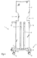
- Fig. 4 For easy handling when moving the To enable radiation protection device 1 shows in Fig. 4 embodiment shown side handles 16 at about elbow height. Through the handles 16 on the one hand prevents the radiation shield 2 from touching the side when moving is soiled that frequent wiping of hand and fingerprints can be omitted, on the other hand, the user visualizes immediately the correct height of the hand position when moving the radiation protection device 1, so that the risk of Tilting of the radiation protection device 1 is reduced.
- the handles 16 can, as shown on the right in FIG. 4, can be folded down so that they are not when not in use to hinder.
- FIG. 5 shows a further advantageous exemplary embodiment a radiation protection device 1 according to the invention.
- the radiation protection device 1 also in the range of Diagnostic devices with so-called C-tubes are used which is among the patient's Examination couch extends, it may be advantageous to Radiation protection screen 2 from damage and scratches to protect by a base 17.
- the base 17 has the same radius of curvature as the radiation shield 2 and is connected to the double cross-shaped foot 7. This can be done as in the previous ones Embodiments just be formed, he can but also curved under a similar radius of curvature be like the radiation shield 2.
- the base 17 is then met by a suitable choice of material a multiple task.
- the Radiation shield 2 protected from damage, for another can be any height adjustment 10 in the Socket 17 can be accommodated, for. B. the above already mentioned gas pressure springs 11.
- the radiation shield 2 is guided and stabilized in the hollow base 17.
- the invention is not based on those described Embodiments limited. In particular, any Combinations of the individual characteristics possible.
Landscapes
- Engineering & Computer Science (AREA)
- Health & Medical Sciences (AREA)
- Life Sciences & Earth Sciences (AREA)
- Medical Informatics (AREA)
- Physics & Mathematics (AREA)
- High Energy & Nuclear Physics (AREA)
- Pathology (AREA)
- Heart & Thoracic Surgery (AREA)
- Nuclear Medicine, Radiotherapy & Molecular Imaging (AREA)
- Optics & Photonics (AREA)
- General Engineering & Computer Science (AREA)
- Radiology & Medical Imaging (AREA)
- Biomedical Technology (AREA)
- Biophysics (AREA)
- Molecular Biology (AREA)
- Surgery (AREA)
- Animal Behavior & Ethology (AREA)
- General Health & Medical Sciences (AREA)
- Public Health (AREA)
- Veterinary Medicine (AREA)
- Apparatus For Radiation Diagnosis (AREA)
Abstract
Description
- Fig. 1
- ein erstes Ausführungsbeispiel einer erfindungsgemäßen Strahlenschutzvorrichtung;
- Fig. 2
- ein zweites Ausführungsbeispiel einer erfindungsgemäßen Strahlenschutzvorrichtung;
- Fig. 3
- ein drittes Ausführungsbeispiel einer erfindungsgemäßen Strahlenschutzvorrichtung;
- Fig. 4
- ein viertes Ausführungsbeispiel einer erfindungsgemäßen Strahlenschutzvorrichtung; und
- Fig. 5
- ein fünftes Ausführungsbeispiel einer erfindungsgemäßen Strahlenschutzvorrichtung.
Claims (32)
- Strahlenschutzvorrichtung (1) zur Abschirmung einer von einer Strahlungsquelle, insbesondere einer Röntgenquelle, abgestrahlten Strahlung, wobei die Strahlenschutzvorrichtung (1) eine die Strahlung absorbierenden, transparenten Strahlenschutzscheibe (2) umfaßt, welche an einer Standvorrichtung (3) fixiert ist,
dadurch gekennzeichnet, daß die Strahlenschutzscheibe (2) gewölbt ausgeführt ist und in stehender Körperhaltung eines Benutzers körpernah führbar ist. - Strahlenschutzvorrichtung nach Anspruch 1,
dadurch gekennzeichnet, daß die Standvorrichtung (3) zumindest eine Leiste (6) umfaßt. - Strahlenschutzvorrichtung nach Anspruch 2,
dadurch gekennzeichnet, daß die Strahlenschutzscheibe (2) an der zumindest einen Leiste (6) fixiert ist. - Strahlenschutzvorrichtung nach Anspruch 3,
dadurch gekennzeichnet, daß die Fixierung mittels Schrauben (4), Bolzen oder ähnlicher Befestigungsvorrichtungen erfolgt. - Strahlenschutzvorrichtung nach einem der Ansprüche 2 bis 4,
dadurch gekennzeichnet, daß die zumindest eine Leiste (6) an der Standvorrichtung (3) und der Strahlenschutzscheibe (2) fixiert ist und sich parallel zu letzterer erstreckt. - Strahlenschutzvorrichtung nach Anspruch 1,
dadurch gekennzeichnet, daß zwei Leisten (6) vorgesehen sind. - Strahlenschutzvorrichtung nach Anspruch 6,
dadurch gekennzeichnet, daß sich die zwei Leisten (6) entlang Außenkanten (17) der Strahlenschutzscheibe (2) erstrecken. - Strahlenschutzvorrichtung nach einem der Ansprüche 1 bis 7,
dadurch gekennzeichnet, daß die Standvorrichtung (3) einen doppelkreuzförmigen Fuß (7) aufweist. - Strahlenschutzvorrichtung nach Anspruch 8,
dadurch gekennzeichnet, daß der Fuß (7) vier Arme (8) aufweist. - Strahlenschutzvorrichtung nach Anspruch 9,
dadurch gekennzeichnet, daß ein dem Benutzer angewandter Arm (8) länger als die übrigen Arme (8) ausgebildet ist. - Strahlenschutzvorrichtung nach Anspruch 9 oder 10,
dadurch gekennzeichnet, daß an den Armen (8) endständige bremsbare Rollen (9) angeordnet sind. - Strahlenschutzvorrichtung nach einem der Ansprüche 1 bis 11,
dadurch gekennzeichnet, daß die Strahlenschutzscheibe (2) höhenverstellbar an der Standvorrichtung (3) fixiert ist. - Strahlenschutzvorrichtung nach Anspruch 12,
dadurch gekennzeichnet, daß eine Höhenverstellung (10) zumindest eine Gasdruckfeder (11) umfaßt. - Strahlenschutzvorrichtung nach Anspruch 13,
dadurch gekennzeichnet, daß die zumindest eine Gasdruckfeder (11) in der zumindest einen Leiste (6) angeordnet ist. - Strahlenschutzvorrichtung nach Anspruch 12,
dadurch gekennzeichnet, daß die Höhenverstellung (10) in Form einer mechanischen Höhenverstellung (10), einer hydraulischen Höhenverstellung (10) oder einer elektrischen Höhenverstellung (10) ausgebildet ist. - Strahlenschutzvorrichtung nach einem der Ansprüche 1 bis 15,
dadurch gekennzeichnet, daß die Strahlenschutzscheibe (2) Ausnehmungen (5) aufweist. - Strahlenschutzvorrichtung nach Anspruch 16,
dadurch gekennzeichnet, daß die Ausnehmungen (5) der Strahlenschutzscheibe (2) asymmetrisch sind. - Strahlenschutzvorrichtung nach Anspruch 16 oder 17,
dadurch gekennzeichnet, daß die Ausnehmungen (5) durch Bleilappen (15) abdeckbar sind. - Strahlenschutzvorrichtung nach Anspruch 18,
dadurch gekennzeichnet, daß die Bleilappen (15) mittels Leisten (13), Druckknöpfen (14) oder Klettbändern an der Strahlenschutzscheibe (2) fixiert sind. - Strahlenschutzvorrichtung nach einem der Ansprüche 1 bis 19,
dadurch gekennzeichnet, daß die Strahlenschutzscheibe (2) an einem unteren Ende eine Bleischürze (12) aufweist. - Strahlenschutzvorrichtung nach Anspruch 20,
dadurch gekennzeichnet, daß die Bleischürze (12) mittels Leisten (13), Druckknöpfen (14) oder Klettbändern an der Strahlenschutzscheibe (2) fixiert ist. - Strahlenschutzvorrichtung nach Anspruch 20 oder 21,
dadurch gekennzeichnet, daß die Bleischürze (12) aus mehreren, einander überlappenden Schürzenteilen (18) besteht. - Strahlenschutzvorrichtung nach einem der Ansprüche 1 bis 22,
dadurch gekennzeichnet, daß die Strahlenschutzvorrichtung (1) Handgriffe (16) aufweist. - Strahlenschutzvorrichtung nach Anspruch 23,
dadurch gekennzeichnet, daß die Handgriffe (16) seitlich in Ellenbogenhöhe an der Strahlenschutzscheibe (2) abgebracht sind. - Strahlenschutzvorrichtung nach Anspruch 23 oder 24,
dadurch gekennzeichnet, daß die Handgriffe (16) herunterklappbar sind. - Strahlenschutzvorrichtung nach einem der Ansprüche 1 bis 25,
dadurch gekennzeichnet, daß die Strahlenschutzscheibe (2) in einem Sockel (17) angeordnet ist. - Strahlenschutzvorrichtung nach Anspruch 26,
dadurch gekennzeichnet, daß der Sockel (17) mit dem Fuß (7) verbunden ist. - Strahlenschutzvorrichtung nach Anspruch 26 oder 27,
dadurch gekennzeichnet, daß der Sockel (17) unter dem gleichen Krümmungsradius wie die Strahlenschutzscheibe (2) gekrümmt ist. - Strahlenschutzvorrichtung nach einem der Ansprüche 26 bis 28,
dadurch gekennzeichnet, daß der Fuß (7) unter dem gleichen Krümmungsradius wie der Sockel (17) gekrümmt ist. - Strahlenschutzvorrichtung nach einem der Ansprüche 26 bis 29,
dadurch gekennzeichnet, daß der Sockel (17) Strahlenschutzmaterial enthält. - Strahlenschutzvorrichtung nach einem der Ansprüche 26 bis 30,
dadurch gekennzeichnet, daß in den Sockel (17) eine Höhenverstellung (10) integriert ist. - Strahlenschutzvorrichtung nach einem der Ansprüche 1 bis 31,
dadurch gekennzeichnet, daß die Strahlenschutzscheibe (2) aus Bleiacryl besteht.
Applications Claiming Priority (2)
| Application Number | Priority Date | Filing Date | Title |
|---|---|---|---|
| DE20307606U | 2003-05-15 | ||
| DE20307606U DE20307606U1 (de) | 2003-05-15 | 2003-05-15 | Strahlenschutzvorrichtung mit transparenter Strahlenschutzscheibe |
Publications (2)
| Publication Number | Publication Date |
|---|---|
| EP1477992A1 true EP1477992A1 (de) | 2004-11-17 |
| EP1477992B1 EP1477992B1 (de) | 2009-12-30 |
Family
ID=27816397
Family Applications (1)
| Application Number | Title | Priority Date | Filing Date |
|---|---|---|---|
| EP04007089A Expired - Lifetime EP1477992B1 (de) | 2003-05-15 | 2004-03-24 | Strahlenschutzvorrichtung mit transparenter Strahlenschutzscheibe |
Country Status (2)
| Country | Link |
|---|---|
| EP (1) | EP1477992B1 (de) |
| DE (2) | DE20307606U1 (de) |
Cited By (4)
| Publication number | Priority date | Publication date | Assignee | Title |
|---|---|---|---|---|
| WO2007060561A3 (en) * | 2005-11-23 | 2007-10-18 | Koninkl Philips Electronics Nv | Radiation shielding for tomographic scanners |
| CN100438832C (zh) * | 2006-05-12 | 2008-12-03 | 吴文质 | 可调式立位照射x光检查保护屏 |
| RU2428117C1 (ru) * | 2010-04-19 | 2011-09-10 | Общество с ограниченной ответственностью "С.П.ГЕЛПИК" | Защитная ширма |
| US11382576B2 (en) * | 2018-04-24 | 2022-07-12 | Koninklijke Philips N.V. | Ergonomic support device for users in medical environment |
Families Citing this family (4)
| Publication number | Priority date | Publication date | Assignee | Title |
|---|---|---|---|---|
| DE102004039411A1 (de) * | 2004-08-13 | 2006-02-23 | Siemens Ag | Röntgenvorrichtung mit mitgeführtem Streustrahlenschutz |
| DE102010061893B4 (de) | 2010-11-24 | 2020-03-12 | Mavig Gmbh | Strahlenschutzvorrichtung |
| DE102013203812B4 (de) | 2013-03-06 | 2017-04-13 | Mavig Gmbh | Fahrbare Strahlenschutzanordnung |
| CN106782726B (zh) * | 2016-12-30 | 2018-05-04 | 郑州大学第一附属医院 | 一种医用介入放射防护装置 |
Citations (5)
| Publication number | Priority date | Publication date | Assignee | Title |
|---|---|---|---|---|
| US4023219A (en) * | 1972-09-29 | 1977-05-17 | Infranor S.A. | Nuclear accident carrier |
| US4581538A (en) * | 1983-09-30 | 1986-04-08 | Colonial X-Ray Corporation | Radiation shield |
| EP0345548A1 (de) * | 1988-06-08 | 1989-12-13 | Siemens Aktiengesellschaft | Strahlenschutzvorrichtung |
| DE4301908A1 (de) * | 1993-01-25 | 1994-08-04 | Siemens Ag | Verstellbare Strahlenschutzwand |
| DE19643623A1 (de) * | 1996-10-22 | 1998-04-23 | Hans Dipl Phys Schoefer | Strahlenschutzstuhl |
Family Cites Families (1)
| Publication number | Priority date | Publication date | Assignee | Title |
|---|---|---|---|---|
| DE19924914A1 (de) | 1999-05-31 | 2000-12-21 | Lozano Saavedra Jeremias | Zum Zwecke der Durchführung von med. Eingriffen variable und transportable Strahlenschutzwand |
-
2003
- 2003-05-15 DE DE20307606U patent/DE20307606U1/de not_active Expired - Lifetime
-
2004
- 2004-03-24 DE DE502004010571T patent/DE502004010571D1/de not_active Expired - Lifetime
- 2004-03-24 EP EP04007089A patent/EP1477992B1/de not_active Expired - Lifetime
Patent Citations (5)
| Publication number | Priority date | Publication date | Assignee | Title |
|---|---|---|---|---|
| US4023219A (en) * | 1972-09-29 | 1977-05-17 | Infranor S.A. | Nuclear accident carrier |
| US4581538A (en) * | 1983-09-30 | 1986-04-08 | Colonial X-Ray Corporation | Radiation shield |
| EP0345548A1 (de) * | 1988-06-08 | 1989-12-13 | Siemens Aktiengesellschaft | Strahlenschutzvorrichtung |
| DE4301908A1 (de) * | 1993-01-25 | 1994-08-04 | Siemens Ag | Verstellbare Strahlenschutzwand |
| DE19643623A1 (de) * | 1996-10-22 | 1998-04-23 | Hans Dipl Phys Schoefer | Strahlenschutzstuhl |
Cited By (5)
| Publication number | Priority date | Publication date | Assignee | Title |
|---|---|---|---|---|
| WO2007060561A3 (en) * | 2005-11-23 | 2007-10-18 | Koninkl Philips Electronics Nv | Radiation shielding for tomographic scanners |
| US7648273B2 (en) | 2005-11-23 | 2010-01-19 | Koninklijke Philips Electronics N.V. | Radiation shielding for tomographic scanners |
| CN100438832C (zh) * | 2006-05-12 | 2008-12-03 | 吴文质 | 可调式立位照射x光检查保护屏 |
| RU2428117C1 (ru) * | 2010-04-19 | 2011-09-10 | Общество с ограниченной ответственностью "С.П.ГЕЛПИК" | Защитная ширма |
| US11382576B2 (en) * | 2018-04-24 | 2022-07-12 | Koninklijke Philips N.V. | Ergonomic support device for users in medical environment |
Also Published As
| Publication number | Publication date |
|---|---|
| EP1477992B1 (de) | 2009-12-30 |
| DE502004010571D1 (de) | 2010-02-11 |
| DE20307606U1 (de) | 2003-09-04 |
Similar Documents
| Publication | Publication Date | Title |
|---|---|---|
| EP3225169B1 (de) | Fahrbare strahlenschutzanordnung | |
| DE10325567B4 (de) | Strahlenschutzanordnung mit separierbarer Umhüllung | |
| EP2509506B1 (de) | Strahlenschutzvorrichtung | |
| EP0832603B1 (de) | Patientenuntersuchungstisch | |
| DE60122299T2 (de) | Chirurgischer tisch mit verschiebungsvorrichtung | |
| DE102010061893B4 (de) | Strahlenschutzvorrichtung | |
| EP0345548A1 (de) | Strahlenschutzvorrichtung | |
| WO2007088089A1 (de) | Mammografiegerät | |
| DE3915381A1 (de) | Liege fuer einen lithotripter | |
| DE102007025935A1 (de) | Kollisionsschutzvorrichtung für eine Patientenliege eines medizinischen Röntgengeräts, Patientenliege mit einer Kollisionsschutzvorrichtung und Röntgengerät | |
| EP1477992B1 (de) | Strahlenschutzvorrichtung mit transparenter Strahlenschutzscheibe | |
| DE60004014T2 (de) | Träger für medizinische zwecke mit einem grossen verstellungsbereich | |
| DE3326880A1 (de) | Schutzvorrichtung | |
| DE8711572U1 (de) | Primärstrahlenblende für Röntgendiagnostikgeräte | |
| DE4325212C2 (de) | Medizinisches Gerät | |
| EP3669380A1 (de) | Schutzhandschuh zur abschirmung durchdringender strahlen | |
| DE202009002358U1 (de) | Behandlungsstuhl | |
| WO1999030628A1 (de) | Arbeitsstuhl für ärzte | |
| DE102017206933B4 (de) | Kompressionseinheit | |
| DE102024210787A1 (de) | Schutzvorrichtung für ein Magnetresonanztomographiegerät | |
| DE29505768U1 (de) | Kranken-/Patiententransporter | |
| DE29711645U1 (de) | Trainingsgerät | |
| DE2259347C3 (de) | Patientendurchreiche | |
| DE1959358A1 (de) | Strahlenschutz gegen Roentgenstrahlen u.dgl. | |
| DE102010062400A1 (de) | Medizinisches Bildgebungssystem und Verfahren zur Bedienung des Bildgebungssystems |
Legal Events
| Date | Code | Title | Description |
|---|---|---|---|
| PUAI | Public reference made under article 153(3) epc to a published international application that has entered the european phase |
Free format text: ORIGINAL CODE: 0009012 |
|
| AK | Designated contracting states |
Kind code of ref document: A1 Designated state(s): AT BE BG CH CY CZ DE DK EE ES FI FR GB GR HU IE IT LI LU MC NL PL PT RO SE SI SK TR |
|
| AX | Request for extension of the european patent |
Extension state: AL LT LV MK |
|
| 17P | Request for examination filed |
Effective date: 20050318 |
|
| AKX | Designation fees paid |
Designated state(s): DE FR GB IT |
|
| 17Q | First examination report despatched |
Effective date: 20061011 |
|
| GRAP | Despatch of communication of intention to grant a patent |
Free format text: ORIGINAL CODE: EPIDOSNIGR1 |
|
| GRAS | Grant fee paid |
Free format text: ORIGINAL CODE: EPIDOSNIGR3 |
|
| GRAA | (expected) grant |
Free format text: ORIGINAL CODE: 0009210 |
|
| AK | Designated contracting states |
Kind code of ref document: B1 Designated state(s): DE FR GB IT |
|
| REG | Reference to a national code |
Ref country code: GB Ref legal event code: FG4D Free format text: NOT ENGLISH |
|
| REF | Corresponds to: |
Ref document number: 502004010571 Country of ref document: DE Date of ref document: 20100211 Kind code of ref document: P |
|
| PLBE | No opposition filed within time limit |
Free format text: ORIGINAL CODE: 0009261 |
|
| STAA | Information on the status of an ep patent application or granted ep patent |
Free format text: STATUS: NO OPPOSITION FILED WITHIN TIME LIMIT |
|
| 26N | No opposition filed |
Effective date: 20101001 |
|
| REG | Reference to a national code |
Ref country code: FR Ref legal event code: PLFP Year of fee payment: 13 |
|
| REG | Reference to a national code |
Ref country code: FR Ref legal event code: PLFP Year of fee payment: 14 |
|
| REG | Reference to a national code |
Ref country code: FR Ref legal event code: PLFP Year of fee payment: 15 |
|
| PGFP | Annual fee paid to national office [announced via postgrant information from national office to epo] |
Ref country code: FR Payment date: 20230321 Year of fee payment: 20 |
|
| PGFP | Annual fee paid to national office [announced via postgrant information from national office to epo] |
Ref country code: GB Payment date: 20230323 Year of fee payment: 20 Ref country code: DE Payment date: 20230324 Year of fee payment: 20 |
|
| PGFP | Annual fee paid to national office [announced via postgrant information from national office to epo] |
Ref country code: IT Payment date: 20230331 Year of fee payment: 20 |
|
| REG | Reference to a national code |
Ref country code: DE Ref legal event code: R071 Ref document number: 502004010571 Country of ref document: DE |
|
| REG | Reference to a national code |
Ref country code: GB Ref legal event code: PE20 Expiry date: 20240323 |
|
| PG25 | Lapsed in a contracting state [announced via postgrant information from national office to epo] |
Ref country code: GB Free format text: LAPSE BECAUSE OF EXPIRATION OF PROTECTION Effective date: 20240323 |