EP1478986B1 - Procede et dispositif pour la regulation du regime d'un moteur a combustion interne - Google Patents
Procede et dispositif pour la regulation du regime d'un moteur a combustion interne Download PDFInfo
- Publication number
- EP1478986B1 EP1478986B1 EP02787391A EP02787391A EP1478986B1 EP 1478986 B1 EP1478986 B1 EP 1478986B1 EP 02787391 A EP02787391 A EP 02787391A EP 02787391 A EP02787391 A EP 02787391A EP 1478986 B1 EP1478986 B1 EP 1478986B1
- Authority
- EP
- European Patent Office
- Prior art keywords
- manipulated variable
- controller
- speed
- variable
- control
- Prior art date
- Legal status (The legal status is an assumption and is not a legal conclusion. Google has not performed a legal analysis and makes no representation as to the accuracy of the status listed.)
- Expired - Lifetime
Links
- 238000002485 combustion reaction Methods 0.000 title claims abstract description 21
- 238000000034 method Methods 0.000 title claims abstract description 20
- 230000008859 change Effects 0.000 claims description 12
- 238000004590 computer program Methods 0.000 claims description 6
- 230000007423 decrease Effects 0.000 claims description 5
- 230000001276 controlling effect Effects 0.000 description 10
- 230000006399 behavior Effects 0.000 description 5
- 239000000446 fuel Substances 0.000 description 4
- 230000006870 function Effects 0.000 description 3
- 230000008901 benefit Effects 0.000 description 2
- 230000033228 biological regulation Effects 0.000 description 2
- 230000005540 biological transmission Effects 0.000 description 2
- 238000004364 calculation method Methods 0.000 description 2
- 230000003247 decreasing effect Effects 0.000 description 2
- 238000001514 detection method Methods 0.000 description 2
- 238000010586 diagram Methods 0.000 description 2
- 230000001105 regulatory effect Effects 0.000 description 2
- 230000009471 action Effects 0.000 description 1
- 238000013459 approach Methods 0.000 description 1
- 238000012937 correction Methods 0.000 description 1
- 238000013461 design Methods 0.000 description 1
- 238000011161 development Methods 0.000 description 1
- 230000000694 effects Effects 0.000 description 1
- 238000010304 firing Methods 0.000 description 1
- 230000006872 improvement Effects 0.000 description 1
- 238000002347 injection Methods 0.000 description 1
- 239000007924 injection Substances 0.000 description 1
- 230000003993 interaction Effects 0.000 description 1
- 230000007935 neutral effect Effects 0.000 description 1
- 230000008092 positive effect Effects 0.000 description 1
- 238000004886 process control Methods 0.000 description 1
- 230000009467 reduction Effects 0.000 description 1
- 230000004044 response Effects 0.000 description 1
- 230000001052 transient effect Effects 0.000 description 1
- 230000007704 transition Effects 0.000 description 1
Images


Classifications
-
- G—PHYSICS
- G05—CONTROLLING; REGULATING
- G05B—CONTROL OR REGULATING SYSTEMS IN GENERAL; FUNCTIONAL ELEMENTS OF SUCH SYSTEMS; MONITORING OR TESTING ARRANGEMENTS FOR SUCH SYSTEMS OR ELEMENTS
- G05B11/00—Automatic controllers
- G05B11/01—Automatic controllers electric
- G05B11/36—Automatic controllers electric with provision for obtaining particular characteristics, e.g. proportional, integral, differential
-
- F—MECHANICAL ENGINEERING; LIGHTING; HEATING; WEAPONS; BLASTING
- F02—COMBUSTION ENGINES; HOT-GAS OR COMBUSTION-PRODUCT ENGINE PLANTS
- F02D—CONTROLLING COMBUSTION ENGINES
- F02D31/00—Use of speed-sensing governors to control combustion engines, not otherwise provided for
- F02D31/001—Electric control of rotation speed
-
- F—MECHANICAL ENGINEERING; LIGHTING; HEATING; WEAPONS; BLASTING
- F02—COMBUSTION ENGINES; HOT-GAS OR COMBUSTION-PRODUCT ENGINE PLANTS
- F02D—CONTROLLING COMBUSTION ENGINES
- F02D41/00—Electrical control of supply of combustible mixture or its constituents
- F02D41/02—Circuit arrangements for generating control signals
- F02D41/0205—Circuit arrangements for generating control signals using an auxiliary engine speed control
-
- F—MECHANICAL ENGINEERING; LIGHTING; HEATING; WEAPONS; BLASTING
- F02—COMBUSTION ENGINES; HOT-GAS OR COMBUSTION-PRODUCT ENGINE PLANTS
- F02D—CONTROLLING COMBUSTION ENGINES
- F02D41/00—Electrical control of supply of combustible mixture or its constituents
- F02D41/02—Circuit arrangements for generating control signals
- F02D41/14—Introducing closed-loop corrections
- F02D41/1401—Introducing closed-loop corrections characterised by the control or regulation method
- F02D41/1402—Adaptive control
-
- F—MECHANICAL ENGINEERING; LIGHTING; HEATING; WEAPONS; BLASTING
- F02—COMBUSTION ENGINES; HOT-GAS OR COMBUSTION-PRODUCT ENGINE PLANTS
- F02D—CONTROLLING COMBUSTION ENGINES
- F02D41/00—Electrical control of supply of combustible mixture or its constituents
- F02D41/02—Circuit arrangements for generating control signals
- F02D41/14—Introducing closed-loop corrections
- F02D41/1401—Introducing closed-loop corrections characterised by the control or regulation method
- F02D2041/1413—Controller structures or design
- F02D2041/1418—Several control loops, either as alternatives or simultaneous
Definitions
- the invention relates to a method and a device for controlling the speed of the internal combustion engine.
- DE 40 16 018 C1 describes a circuit arrangement for process control, in particular for controlling a flow.
- the problem arises that the actual value detection covers a large measuring range, wherein the corresponding sensor has different accuracies in different measuring ranges, ie. H.
- different transducers for detecting the actual value are used for different measuring ranges. These two measured values are fed to two controllers, to which essentially the same reference value is supplied.
- the setpoint is filtered accordingly in a branch.
- At least a first controller based on a comparison between a first setpoint and an actual value, specifies a first control variable and this first control variable is limited to a first control range such that the variable to be controlled decreases and that at least one second Controller, based on a comparison between a second setpoint and the actual value specifies a second control variable and this second control variable is limited to a second control range such that the variable to be controlled increases.
- the first controller only supplies the manipulated variables within a certain setting range.
- the second controller supplies the manipulated variable only within a second setting range.
- Both the first and the second controller are preferably designed as a proportional controller or as a proportional and integral controller. In the example of a speed controller, which controls this over the amount of fuel, this means that the first controller can only reduce the amount of fuel and the second controller can only increase the amount of fuel.
- the first setpoint is always greater than or equal to the second setpoint.
- the manipulated variable with the largest change in magnitude is used for actuation.
- the manipulated variable of the other controller that is, the controller with the absolute smallest change, is frozen.
- the computer program according to the invention has program code means for carrying out all steps of the method according to the invention when the program is executed on a computer, in particular a control unit for an internal combustion engine of a motor vehicle.
- a control unit for an internal combustion engine of a motor vehicle in particular a control unit for an internal combustion engine of a motor vehicle.
- the Invention realized by a program stored in the controller, so that this provided with the program control unit in the same way the invention as the method to whose execution the program is suitable.
- the computer program product according to the invention has program code means which are stored on a computer-readable data carrier in order to carry out the method according to the invention when the program product is executed on a computer, in particular a control unit for an internal combustion engine of a motor vehicle.
- the invention is realized by a data carrier, so that the inventive method can be performed when the program product or the data carrier is integrated into a control device for an internal combustion engine, in particular a motor vehicle.
- disk or as Computer program product can be used in particular an electrical storage medium, for example a read-only memory (ROM), an EPROM or a permanent electrical memory such as a CD-ROM or DVD.
- FIG. 1 shows a device for controlling an internal combustion engine.
- the internal combustion engine is designated 100.
- various sensors are arranged, which detect different signals.
- a speed sensor 110 is provided, which supplies a signal NI which corresponds to the measured speed of the internal combustion engine.
- actuators 120 are arranged on the internal combustion engine, which influence the power output of the internal combustion engine and thus the speed of the internal combustion engine.
- adjusting elements 120 are provided which control the torque provided by the internal combustion engine in particular via the injected fuel quantity.
- the actuator 120 is preferably acted upon by a control unit 130 with drive signals.
- the output signal NI of the sensor 110 likewise reaches the control unit 130.
- signals of further sensors 140 are fed to the control unit 130.
- an accelerator pedal position transmitter is used in particular.
- this control unit calculates a drive signal for actuating the control elements 120.
- an idling controller for regulating and / or controlling the rotational speed, in particular in diesel engines, an idling controller, a working speed controller, a driving speed controller, an end speed controller, a maximum speed control, a general speed controller and / or a speed controller provided.
- a speed limit serve in particular the final speed controller, the working speed controller and / or the cruise control.
- the idle controller ensures that the speed of the internal combustion engine does not fall below the idling speed.
- the vehicle speed controller ensures that the rpm complies with a specific value which corresponds to the desired vehicle speed. Accordingly, the working speed controller ensures that the speed does not drop below a desired working speed.
- the final speed controller and the maximum speed control ensure compliance with an upper speed limit.
- the final speed controller ensures in particular that a maximum speed is not reached.
- the maximum speed reduction ensures that a speed that corresponds to a desired maximum speed or a permissible maximum speed is not exceeded.
- the special case that the upper speed limit corresponds to the lower speed limit is given in particular when regulated in an automated transmission, a specific speed for the switching by the general speed controller becomes.
- a speed controller when the driving specification of the driver's request is interpreted as the setpoint speed. This applies in particular to special applications in the commercial vehicle sector.
- each of the mentioned functions is realized by a separate controller.
- These regulators generally have different engagement points. Problems occur when several controllers are engaged at the same time. This leads to instabilities. Furthermore, problems arise when switching from one to the other functionality. An example is the replacement of idle control by a working speed control. In this case, the problem occurs that the setting intervention of the first controller is suitable to take over in the second. Ie. the initialization of the individual controllers during the transition is problematic.
- a speed interval controller which prevents independent of the controlling intervention of the controller leaving the speed interval.
- the controller completely compensates for the control intervention to maintain the setpoint speed.
- the controller behaves as neutral as possible when the speed is within the interval limits due to the controlling intervention or due to other disturbances.
- Such a speed controller is with appropriate wiring of the interval limits, d. H. with a suitable specification of the setpoints able to realize all or even only a part of the above-mentioned functionalities.
- a speed interval controller is realized by a parallel structure of two controllers.
- the two parallel controllers have PI behavior.
- One of the two controllers regulates to an upper interval limit as upper setpoint NSO.
- the other controller controls the lower interval limit as the lower setpoint NSU.
- the control intervention is limited so that the permissible setpoint interval is not left.
- the lower limit of its control intervention is thus 0.
- the upper limit is preferably the control intervention permissible at the current operating point.
- the controller path for the upper speed limit can only intervene in a decreasing manner.
- the upper limit of its control intervention is 0.
- the lower limit can be, for example, the current control value for the control intervention. This ensures that when the upper interval limit is exceeded, the controlling control intervention can be canceled by the controller intervention.
- the interaction of the two regulator paths allows both increasing and decreasing interventions.
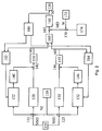
- a corresponding controller structure is shown as a block diagram in FIG. Already described in Figure 1 elements are designated by corresponding reference numerals.
- the output signal NI of the rotational speed sensor 110 passes via a first node 115 to a first P component 120 and a first I component 122. Furthermore, this signal passes via a second node 125 to a second P component 130 and a second I component 132nd
- At the second input of the first node 115 is a first output signal NSO a setpoint input 135, and at the second node 125 is the output signal NSO the setpoint input 135 at.
- the output signal of the first integral component 122 passes through a first limiter 140 to a node 142. At the second input of the node 142 is the output of the first P-portion 120.
- the output of the second integral portion 132 passes through a second limiter 144 to a node 146, at the second input, the output signal of the second proportional component 130 is present.
- the output signal of the connection point 142 is applied to a first manipulated variable limiter 150 whose output signal MO reaches an interlocking 160.
- the output signal of the connection point 146 is applied to a second manipulated variable limiter 155, whose output signal MU likewise arrives at the interlocking 160.
- the output signal of the circuit 160 passes through a node 162 to the signal limit 165, with the output signal M, the actuator 130 is acted upon or from which a signal for acting on the control element 130 is calculated.
- At the second input of the node 162 is the output of a node 170, which is acted upon on the one hand with the output signal W of a weighting instruction 172 and on the other with the signal of a differential component 174.
- the output signal of the control variable limit 165 also arrives at a starting value specification 180, which in turn acts on a first starting value specification 182 and a second starting value specification 184.
- the first starting value input 182 is further supplied with the output signal MO of the first manipulated variable limiting. Accordingly, the second starting value input 184, the output signal MU of the second control variable limit 155 is supplied.
- the integral component 122, the first limiter 140 and the proportional component 120 form a first regulator which regulates the rotational speed to the upper interval limit NSO.
- the manipulated variable limiter 150 limits the output signal of this controller to negative values, ie. H. this controller has only one moment reducing intervention. Ie. the upper limit of this limiter assumes the value 0.
- the proportional component (P component) 130 and the integral component (I component) 132 and the second limiter 144 form a second controller which regulates the rotational speed to the lower interval limit NSU.
- the limiter 155 is designed such that this regulator can only perform a torque-increasing intervention, ie the output signal MU of this regulator branch is limited such that the smallest possible value is 0.
- connection 160 selects the corresponding manipulated variable on the basis of these two manipulated variables MU and MO. This is corrected in the node 162 with the weighted output signal of a D component 174.
- the use of the D component 174 results in improved control quality. Especially with setpoint jumps or transient response at an interval limit, this D component has a positive effect on the control behavior. This correction takes place only in selected operating states.
- the following procedure is used for connecting the control inputs of the parallel control loops.
- path is dynamically switched, ie used to control the control element, which has the magnitude greater change.
- the integrator of the respective other path is set by the corresponding starting value specification 182 or 184 such that the current one Control deviation last represents effective intervention again.
- the inactive path is thus virtually frozen.
- a first step 300 the manipulated variable MO of the first path is determined by the blocks 120, 122, 140 and 142 and the manipulated variable MU of the second path is determined by the blocks 130, 132, 144 and 146.
- step 310 in each case the difference DMO between the new manipulated variable MO and the manipulated variable MOA calculated during the last calculation is determined. Accordingly, the difference DMO of the second control loop is determined on the basis of the current value MU and the preceding MUA.
- the subsequent query 320 checks whether the difference DMO of the first control loop is greater than 0, ie. H. whether the manipulated variable MO increases. If this is not the case, d. H.
- step 340 checks whether the difference DMU is greater than 0. Ie. It is checked whether the controlled variable of the second control loop also increases. If this is the case, d. H. If the first manipulated variable drops and the second manipulated variable increases, step 340 follows. If query 330 recognizes that second manipulated variable DMO likewise drops, that is to say less than 0, step 350 follows. Interrogation 320 recognizes that the first manipulated variable is increasing , d. H. the difference DMO is greater than 0, then the query 335 follows, which checks whether the difference DMU of the second manipulated variable is greater than 0. If this is the case, d. H. The second manipulated variable DMO increases, so also follows step 350. If the second manipulated variable is less than 0, d. H. the first manipulated variable increases and the second manipulated variable decreases, also follows step 340.
- step 340 follows. That means the two manipulated variables are added to the output size M. If the manipulated variables are not in opposite directions, ie both manipulated variables increase or both manipulated variables drop, then in step 350 the magnitude of the change of the manipulated variables is determined in each case.
- the quantity BMO corresponding to the amount of the quantity DMO and the size BMU corresponding to the amount of the quantity DMU are determined.
- Query 360 checks to see if size BMO is greater than size BMU.
- the manipulated variable MO of the first control loop is used for control in step 370.
- the 1-part of the second control loop is frozen to its previous value, ie the I-part is set with the value MUA.
- the manipulated variable of the second control loop is used for control in step 380 and the I-portion 122 of the first control loop is occupied by the value MOA.
- the manipulated variable is used with the magnitude largest change for driving when both controllers provide a manipulated variable.
- the D component 174 is active only in certain operating states. When the D component 174 is switched off, its intervention is taken over by the I components 122 and / or 132 in order to ensure a jump-free course of the manipulated variable M.
- the distribution of the manipulated variable of the D component 174 on the parallel paths is carried out by the starting value specification 180.
- the procedure is as follows: First, it is checked whether the manipulated variable MD of the D component, in particular the weighted manipulated variable, is greater or less than zero. If the manipulated variable MD is greater than 0, then the integral component 122 is assigned as much of MD as possible because of the upper limit 0. The remainder is assigned to integral 132.
- the control concept described is generally applicable to systems that have a controlling intervention on the manipulated variable of the controller.
- the procedure is not limited to a speed control. This can also be used with other regulations.
- switching according to block 160 other strategies are conceivable. For example, a changeover of the two paths can not take place as a function of the magnitude of the manipulated variable, but as a function of the control deviations, in particular the amount of control deviations.
- the functionality in particular when using a computer, can be achieved by the multiple calculation of a path with different parameters and / or limit values.
- the initialization in block 180 other strategies are conceivable. It can be provided that quantities increasing interventions in the second path, ie in particular in the integrator 132 are taken over. Accordingly, for torque-reducing interventions in the first path, in particular in the integral I portion 122 are adopted. Preferably, the initialization will be so carried out that no path as possible reaches the area of the boundary.
- control structures can also be used, in particular with additional proportions or alternative proportions.
- the manipulated variable is the moment.
- other quantities representing the moment may be used.
- the approach can be done on the injection quantity, the throttle position, the firing angle for the rack position or slide path position in edge-controlled systems.
Landscapes
- Engineering & Computer Science (AREA)
- Chemical & Material Sciences (AREA)
- Combustion & Propulsion (AREA)
- Mechanical Engineering (AREA)
- General Engineering & Computer Science (AREA)
- Physics & Mathematics (AREA)
- General Physics & Mathematics (AREA)
- Automation & Control Theory (AREA)
- Electrical Control Of Air Or Fuel Supplied To Internal-Combustion Engine (AREA)
- Combined Controls Of Internal Combustion Engines (AREA)
Abstract
Claims (7)
- Procédé de régulation du régime du moteur à combustion interne, comprenant au moins un premier régulateur (120, 122, 140) qui détermine une première grandeur de réglage (MO) à partir d'une comparaison (115) entre une première valeur de consigne (NSO) et une valeur réelle (NI), et au moins un deuxième régulateur (130, 132, 144) qui détermine une deuxième grandeur de réglage (MU) à partir d'une comparaison (125) entre une deuxième valeur de consigne (NSU) et la valeur réelle (NI),
caractérisé en ce que
la première grandeur de réglage (MO) est limitée à une première plage de réglage de sorte que la grandeur à réguler diminue, et la deuxième grandeur de réglage (MU) est limitée à une deuxième plage de réglage de sorte que la grandeur à réguler augmente. - Procédé selon la revendication 1 ou 2,
caractérisé en ce que
la première valeur de consigne (NSO) est supérieure ou égale à la deuxième valeur de consigne (NSU). - Procédé selon l'une des revendications précédentes,
caractérisé en ce que
dans le cas où les deux régulateurs (120, 122, 140, 130, 132, 144) fournissent une grandeur de réglage (MU, MO), on utilise pour la commande la grandeur de réglage (MU, MO) présentant la plus grande valeur de variation. - Procédé selon la revendication 4,
caractérisé en ce que
la grandeur de réglage avec la plus petite valeur de variation est gelée. - Procédé selon l'une des revendications précédentes,
caractérisé en ce qu'
à des états de fonctionnement déterminés la grandeur de réglage est en outre influencée par un régulateur (172) présentant au moins un comportement différentiel. - Dispositif de régulation du régime du moteur à combustion interne, comprenant au moins un premier régulateur (120, 122, 140) qui détermine une première grandeur de réglage (MO) à partir d'une comparaison (115) entre une première valeur de consigne (NSO) et une valeur réelle (NI), et au moins un deuxième régulateur (130, 132, 144) qui détermine une deuxième grandeur de réglage (MU) à partir d'une comparaison (125) entre une deuxième valeur de consigne (NSU) et la valeur réelle (NI),
caractérisé en ce que
des moyens (150, 155) sont prévus pour limiter la première grandeur de réglage (MO) à une première plage de réglage de sorte que la grandeur à réguler diminue, et pour limiter la deuxième grandeur de réglage (MU) à une deuxième plage de réglage de sorte que la grandeur à réguler augmente. - Programme informatique comprenant des moyens de codage de programme pour la mise en oeuvre d'un procédé pour faire fonctionner un moteur à combustion interne selon au moins l'une des revendications 1 à 6, toutes les étapes étant exécutées selon l'une quelconque des revendications 1 à 6 si le programme est exécuté sur un ordinateur, en particulier un appareil de commande.
Applications Claiming Priority (3)
| Application Number | Priority Date | Filing Date | Title |
|---|---|---|---|
| DE10205375 | 2002-02-09 | ||
| DE10205375A DE10205375A1 (de) | 2002-02-09 | 2002-02-09 | Verfahren und Vorrichtung zur Steuerung einer Brennkraftmaschine, insbesondere zur Regelung der Drehzahl der Brennkraftmaschine |
| PCT/DE2002/004311 WO2003067342A1 (fr) | 2002-02-09 | 2002-11-25 | Procede et dispositif pour la regulation du regime d'un moteur a combustion interne |
Publications (2)
| Publication Number | Publication Date |
|---|---|
| EP1478986A1 EP1478986A1 (fr) | 2004-11-24 |
| EP1478986B1 true EP1478986B1 (fr) | 2007-05-09 |
Family
ID=27618491
Family Applications (1)
| Application Number | Title | Priority Date | Filing Date |
|---|---|---|---|
| EP02787391A Expired - Lifetime EP1478986B1 (fr) | 2002-02-09 | 2002-11-25 | Procede et dispositif pour la regulation du regime d'un moteur a combustion interne |
Country Status (6)
| Country | Link |
|---|---|
| US (1) | US6925985B2 (fr) |
| EP (1) | EP1478986B1 (fr) |
| JP (1) | JP4225916B2 (fr) |
| CN (1) | CN1302346C (fr) |
| DE (2) | DE10205375A1 (fr) |
| WO (1) | WO2003067342A1 (fr) |
Cited By (1)
| Publication number | Priority date | Publication date | Assignee | Title |
|---|---|---|---|---|
| DE102010001696A1 (de) * | 2010-02-09 | 2011-08-11 | ZF Friedrichshafen AG, 88046 | Verfahren zum Einstellen einer fahrerwunschabhängigen Soll-Drehzahl |
Families Citing this family (10)
| Publication number | Priority date | Publication date | Assignee | Title |
|---|---|---|---|---|
| DE102005042650B4 (de) * | 2005-09-08 | 2017-10-12 | Robert Bosch Gmbh | Drehzahlregelung für eine Brennkraftmaschine im Sturzgasfall |
| DE102007045195B3 (de) * | 2007-09-21 | 2009-03-12 | Mtu Friedrichshafen Gmbh | Verfahren zur Regelung eines stationären Gasmotors |
| US7983812B2 (en) * | 2008-08-04 | 2011-07-19 | Scott Potter & Associates, Llc | Method and apparatus for managing battery power in emergency vehicles |
| DE102010003539A1 (de) | 2010-03-31 | 2011-10-06 | Robert Bosch Gmbh | Verfahren und Schaltungsanordnung zur Bestimmung von Position-Minus-Zeit |
| US9823629B2 (en) | 2010-11-16 | 2017-11-21 | Siemens Aktiengesellschaft | Dual loop control system with interactive automatic tracking mode |
| DE102011078609A1 (de) * | 2011-07-04 | 2013-01-10 | Robert Bosch Gmbh | Verfahren zum Betreiben einer Brennkraftmaschine |
| US9850841B2 (en) * | 2013-12-11 | 2017-12-26 | General Electric Company | System and program product for controlling exhaust gas temperature of engine system |
| DE102015208687B4 (de) | 2015-05-11 | 2021-07-15 | Robert Bosch Gmbh | Verfahren zum Ermitteln eines Gesamtmassenträgheitsmoments eines Antriebsstrangs |
| CN107463717A (zh) * | 2016-06-03 | 2017-12-12 | 罗伯特·博世有限公司 | 用于求取传动系的总质量惯性矩的方法 |
| DE102017200839A1 (de) * | 2017-01-19 | 2018-07-19 | Robert Bosch Gmbh | Verfahren zum Regeln einer Drehzahl einer elektrischen Maschine |
Family Cites Families (15)
| Publication number | Priority date | Publication date | Assignee | Title |
|---|---|---|---|---|
| GB1416861A (en) * | 1971-12-03 | 1975-12-10 | Cav Ltd | Control systems for internal combustion engines |
| DE3114836A1 (de) * | 1981-04-11 | 1982-11-04 | Robert Bosch Gmbh, 7000 Stuttgart | Steuersystem fuer eine brennkraftmaschine |
| US4422420A (en) * | 1981-09-24 | 1983-12-27 | Trw Inc. | Method and apparatus for fuel control in fuel injected internal combustion engines |
| DE3202614A1 (de) * | 1982-01-27 | 1983-08-04 | Robert Bosch Gmbh, 7000 Stuttgart | Regeleinrichtung fuer den spritzbeginn bei einer mit selbstzuendung arbeitenden brennkraftmaschine |
| JPS60190641A (ja) * | 1984-03-12 | 1985-09-28 | Diesel Kiki Co Ltd | 内燃機関用電子式ガバナ |
| JPH04506389A (ja) * | 1989-07-07 | 1992-11-05 | シーメンス アクチエンゲゼルシヤフト | 低速回転する多シリンダデイーゼルエンジンの回転数調節方法および装置 |
| DE4016018C1 (en) * | 1990-05-18 | 1991-08-08 | Eckardt Ag, 7000 Stuttgart, De | Process regulating circuitry using two measurers in parallel - has range selection stage cooperating with proportional member and lowest and highest value limiting stages |
| ATE152256T1 (de) * | 1992-02-04 | 1997-05-15 | Siemens Ag | Verfahren zur regelung von technischen prozessen mit mehreren reglern |
| US5417193A (en) * | 1994-01-25 | 1995-05-23 | Textron Inc. | Engine speed control system and method |
| DE19620039A1 (de) * | 1996-05-17 | 1997-11-20 | Bosch Gmbh Robert | System zur Steuerung einer Brennkraftmaschine |
| DE19711787A1 (de) | 1996-05-29 | 1997-12-04 | Bosch Gmbh Robert | Verfahren und Vorrichtung zur Regelung einer Brennkraftmaschine |
| US6334424B1 (en) | 1999-03-05 | 2002-01-01 | Toyota Jidosha Kabushiki Kaisha | Control device and control method for vehicle |
| US6539299B2 (en) * | 2000-02-18 | 2003-03-25 | Optimum Power Technology | Apparatus and method for calibrating an engine management system |
| US6363906B1 (en) * | 2000-03-06 | 2002-04-02 | Detroit Diesel Corporation | Idle shutdown override with defeat protection |
| US6678608B2 (en) * | 2001-11-09 | 2004-01-13 | Ford Global Technologies, Llc | Robust interpolation method for improved automative engine control during transient engine operation |
-
2002
- 2002-02-09 DE DE10205375A patent/DE10205375A1/de not_active Withdrawn
- 2002-11-25 WO PCT/DE2002/004311 patent/WO2003067342A1/fr not_active Ceased
- 2002-11-25 JP JP2003566631A patent/JP4225916B2/ja not_active Expired - Fee Related
- 2002-11-25 CN CNB028116143A patent/CN1302346C/zh not_active Expired - Fee Related
- 2002-11-25 US US10/473,510 patent/US6925985B2/en not_active Expired - Lifetime
- 2002-11-25 EP EP02787391A patent/EP1478986B1/fr not_active Expired - Lifetime
- 2002-11-25 DE DE50210139T patent/DE50210139D1/de not_active Expired - Lifetime
Non-Patent Citations (1)
| Title |
|---|
| None * |
Cited By (1)
| Publication number | Priority date | Publication date | Assignee | Title |
|---|---|---|---|---|
| DE102010001696A1 (de) * | 2010-02-09 | 2011-08-11 | ZF Friedrichshafen AG, 88046 | Verfahren zum Einstellen einer fahrerwunschabhängigen Soll-Drehzahl |
Also Published As
| Publication number | Publication date |
|---|---|
| EP1478986A1 (fr) | 2004-11-24 |
| CN1302346C (zh) | 2007-02-28 |
| US6925985B2 (en) | 2005-08-09 |
| US20040149259A1 (en) | 2004-08-05 |
| JP4225916B2 (ja) | 2009-02-18 |
| CN1514961A (zh) | 2004-07-21 |
| DE10205375A1 (de) | 2003-08-21 |
| WO2003067342A1 (fr) | 2003-08-14 |
| JP2005517128A (ja) | 2005-06-09 |
| DE50210139D1 (de) | 2007-06-21 |
Similar Documents
| Publication | Publication Date | Title |
|---|---|---|
| DE3416369C2 (de) | Vorrichtung zur Regelung der Geschwindigkeit eines Fahrzeugs | |
| DE4219791C2 (de) | System zur Regelung der Aufladung einer Brennkraftmaschine | |
| DE3333392A1 (de) | Verfahren zur rueckkopplungssteuerung der leerlaufdrehzahl einer brennkraftmaschine | |
| WO1997043531A1 (fr) | Procede et dispositif permettant d'assurer la commande d'un moteur a combustion interne | |
| DE102007009688A1 (de) | Verfahren und Vorrichtung zum Ermitteln eines gradientenlimitierten Summen-Solldrehmoments aus einem Solldrehmoment einer Drehzahlregelung | |
| EP1478986B1 (fr) | Procede et dispositif pour la regulation du regime d'un moteur a combustion interne | |
| DE4333896B4 (de) | Verfahren und Vorrichtung zur Steuerung einer Brennkraftmaschine | |
| DE10114040B4 (de) | Verfahren und Vorrichtung zur Steuerung der Antriebseinheit eines Fahrzeugs | |
| DE10302263B3 (de) | Verfahren zur Drehzahl-Regelung einer Brennkraftmaschine | |
| DE4223253C2 (de) | Steuereinrichtung für ein Fahrzeug | |
| DE4115647B4 (de) | Steuersystem in einem Fahrzeug | |
| DE19924862C1 (de) | Verfahren zur Einstellung einer vorgebbaren Zielgeschwindigkeit in einem Fahrzeug | |
| EP1896709B1 (fr) | Procédé et dispositif de commande d'un moteur a combustion interne | |
| WO2007090216A2 (fr) | Procede de regulation du systeme d'alimentation en air d'un moteur a combustion interne | |
| EP2173990A1 (fr) | Procédé et dispositif pour actionner une unité de propulsion | |
| EP1309784B1 (fr) | Procede et dispositif pour reguler une grandeur de fonctionnement d'un moteur a combustion interne | |
| EP2729688A1 (fr) | Procédé pour faire fonctionner un moteur à combustion interne | |
| EP3100923B1 (fr) | Regulateur d'acceleration destine a reguler des exigences de freinage permanent et de moteur | |
| DE10156948B4 (de) | Verfahren und Vorrichtung zur Steuerung einer Antriebseinheit eines Fahrzeugs | |
| DE102007062173A1 (de) | Verfahren zum Betreiben einer Brennkraftmaschine und Steuer- oder Regelrichtung für eine Brennkraftmaschine | |
| DE4123347B4 (de) | Einrichtung zur Regelung der Geschwindigkeit eines Kraftfahrzeugs | |
| DE102022200396B4 (de) | Verfahren mit einer hydraulischen Druckmittelversorgungsanordnung und hydraulische Druckmittelversorgungsanordnung | |
| EP1507966B1 (fr) | Procede et dispositif de regulation d'une grandeur de fonctionnement dans un vehicule | |
| WO2011018301A1 (fr) | Procédé pour actionner un clapet d'étranglement d'un moteur à combustion interne | |
| DE19856963A1 (de) | Verfahren und Vorrichtung zur Regelung oder Begrenzung der Geschwindigkeit eines Fahrzeugs |
Legal Events
| Date | Code | Title | Description |
|---|---|---|---|
| PUAI | Public reference made under article 153(3) epc to a published international application that has entered the european phase |
Free format text: ORIGINAL CODE: 0009012 |
|
| 17P | Request for examination filed |
Effective date: 20040909 |
|
| AK | Designated contracting states |
Kind code of ref document: A1 Designated state(s): AT BE BG CH CY CZ DE DK EE ES FI FR GB GR IE IT LI LU MC NL PT SE |
|
| GRAP | Despatch of communication of intention to grant a patent |
Free format text: ORIGINAL CODE: EPIDOSNIGR1 |
|
| RBV | Designated contracting states (corrected) |
Designated state(s): DE FR GB IT SE |
|
| GRAS | Grant fee paid |
Free format text: ORIGINAL CODE: EPIDOSNIGR3 |
|
| GRAA | (expected) grant |
Free format text: ORIGINAL CODE: 0009210 |
|
| AK | Designated contracting states |
Kind code of ref document: B1 Designated state(s): DE FR GB IT SE |
|
| REG | Reference to a national code |
Ref country code: GB Ref legal event code: FG4D Free format text: NOT ENGLISH |
|
| REF | Corresponds to: |
Ref document number: 50210139 Country of ref document: DE Date of ref document: 20070621 Kind code of ref document: P |
|
| REG | Reference to a national code |
Ref country code: SE Ref legal event code: TRGR |
|
| GBT | Gb: translation of ep patent filed (gb section 77(6)(a)/1977) |
Effective date: 20070815 |
|
| ET | Fr: translation filed | ||
| PLBE | No opposition filed within time limit |
Free format text: ORIGINAL CODE: 0009261 |
|
| STAA | Information on the status of an ep patent application or granted ep patent |
Free format text: STATUS: NO OPPOSITION FILED WITHIN TIME LIMIT |
|
| 26N | No opposition filed |
Effective date: 20080212 |
|
| PGFP | Annual fee paid to national office [announced via postgrant information from national office to epo] |
Ref country code: GB Payment date: 20141120 Year of fee payment: 13 Ref country code: SE Payment date: 20141120 Year of fee payment: 13 |
|
| PGFP | Annual fee paid to national office [announced via postgrant information from national office to epo] |
Ref country code: FR Payment date: 20141118 Year of fee payment: 13 |
|
| PGFP | Annual fee paid to national office [announced via postgrant information from national office to epo] |
Ref country code: IT Payment date: 20141125 Year of fee payment: 13 |
|
| GBPC | Gb: european patent ceased through non-payment of renewal fee |
Effective date: 20151125 |
|
| PG25 | Lapsed in a contracting state [announced via postgrant information from national office to epo] |
Ref country code: IT Free format text: LAPSE BECAUSE OF NON-PAYMENT OF DUE FEES Effective date: 20151125 |
|
| REG | Reference to a national code |
Ref country code: FR Ref legal event code: ST Effective date: 20160729 |
|
| PG25 | Lapsed in a contracting state [announced via postgrant information from national office to epo] |
Ref country code: SE Free format text: LAPSE BECAUSE OF NON-PAYMENT OF DUE FEES Effective date: 20151126 |
|
| PG25 | Lapsed in a contracting state [announced via postgrant information from national office to epo] |
Ref country code: GB Free format text: LAPSE BECAUSE OF NON-PAYMENT OF DUE FEES Effective date: 20151125 |
|
| PG25 | Lapsed in a contracting state [announced via postgrant information from national office to epo] |
Ref country code: FR Free format text: LAPSE BECAUSE OF NON-PAYMENT OF DUE FEES Effective date: 20151130 |
|
| PGFP | Annual fee paid to national office [announced via postgrant information from national office to epo] |
Ref country code: DE Payment date: 20170126 Year of fee payment: 15 |
|
| REG | Reference to a national code |
Ref country code: DE Ref legal event code: R119 Ref document number: 50210139 Country of ref document: DE |
|
| PG25 | Lapsed in a contracting state [announced via postgrant information from national office to epo] |
Ref country code: DE Free format text: LAPSE BECAUSE OF NON-PAYMENT OF DUE FEES Effective date: 20180602 |