EP1479228B1 - Agc-detektor und verfahren zur agc-detektion - Google Patents
Agc-detektor und verfahren zur agc-detektion Download PDFInfo
- Publication number
- EP1479228B1 EP1479228B1 EP03702843A EP03702843A EP1479228B1 EP 1479228 B1 EP1479228 B1 EP 1479228B1 EP 03702843 A EP03702843 A EP 03702843A EP 03702843 A EP03702843 A EP 03702843A EP 1479228 B1 EP1479228 B1 EP 1479228B1
- Authority
- EP
- European Patent Office
- Prior art keywords
- pulses
- region
- period
- gating
- porch region
- Prior art date
- Legal status (The legal status is an assumption and is not a legal conclusion. Google has not performed a legal analysis and makes no representation as to the accuracy of the status listed.)
- Expired - Lifetime
Links
- 238000000034 method Methods 0.000 title claims abstract description 15
- 230000000694 effects Effects 0.000 description 5
- 230000004044 response Effects 0.000 description 4
- 230000009471 action Effects 0.000 description 2
- 230000008859 change Effects 0.000 description 2
- 238000010586 diagram Methods 0.000 description 2
- 238000005259 measurement Methods 0.000 description 2
- 230000001360 synchronised effect Effects 0.000 description 2
- 230000008901 benefit Effects 0.000 description 1
- 230000003111 delayed effect Effects 0.000 description 1
- 230000001419 dependent effect Effects 0.000 description 1
- 238000007710 freezing Methods 0.000 description 1
- 230000008014 freezing Effects 0.000 description 1
- 230000009467 reduction Effects 0.000 description 1
Images


Classifications
-
- H—ELECTRICITY
- H04—ELECTRIC COMMUNICATION TECHNIQUE
- H04N—PICTORIAL COMMUNICATION, e.g. TELEVISION
- H04N5/00—Details of television systems
- H04N5/44—Receiver circuitry for the reception of television signals according to analogue transmission standards
- H04N5/52—Automatic gain control
- H04N5/53—Keyed automatic gain control
Definitions
- the present invention relates to an AGC (automatic gain control) detector device for television receivers displaying video pictures consisting of a plurality of horizontal lines to be built up successively, comprising
- the present invention relates to a method for AGC detecting for television receivers displaying video pictures consisting of a plurality of horizontal lines to be built up successively, comprising the steps of
- a so-called digital black level (back porch) automatic gain control for television receivers is already known, wherein the horizontal line frequency is used to determine the level at the back porch region of a video output signal. This is compared to a reference level for black, and the difference is the resulting loop gain error. The resulting loop gain error is integrated, digital/analog-converted and finally applied to an analog AGC amplifier via an analog non-critical first-order post filter in order to keep the video output voltage constant.
- the video output voltage is affected by a negative effect called "airplane flutter" which results from changing multi-path reception.
- airplane flutter a negative effect which results from changing multi-path reception.
- the video output voltage is not kept on a constant level any time, but varying, and sometimes the video output voltage is completely distorted. This negative effect leads to a considerable reduction of picture and sound quality.
- an AGC detector device for television receivers displaying video pictures consisting of a plurality of horizontal lines to be built up successively using gating pulses for AGC, comprising
- a method for AGC detecting for television receivers displaying video pictures consisting of a plurality of horizontal lines to be built up successively using gating pulses for AGC comprising the steps of
- the present invention provides a new AGC detector device and a new method for AGC detecting which are fast enough to follow airplane flutter reception conditions with still good picture and sound impression.
- This is achieved by gating the serration pulse region with multiple (in particular three) time shifted horizontal sync pulses and by taking the error signal from the front porch measurement.
- the gating is changed from back porch to front porch during the serration pulse region of the vertical sync period which lasts 19 to 25 line periods depending on the television standard.
- an advantage of the present invention is that television receivers create good picture and sound impression even under high velocity e.g. in cars. So, the present invention is in particular convenient for mobile television.
- first means for detecting the occurrence of the back porch region of the horizontal sync pulses and second means for detecting the occurrence of the front porch region of the horizontal sync pulses, wherein said first and second detecting means are coupled to said shifting means and at least said first detecting means is coupled to said adjusting means.
- the device is a digital AGC detector device. Namely, the change of the gating from back porch to front porch during the serration pulse region can be done easily because it can happen in the digital domain.
- the present invention can be provided for analog television receivers.
- the gating pulses generating means comprises a PLL circuit which can be a horizontal PLL circuit, and the gating pulses generating means can further comprise a vertical integrator.
- the gating pulses generating means can further comprise a vertical integrator.
- the gating pulses can be also derived from a conventional sync slicer.
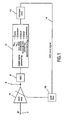
- FIG. 1 A schematic block diagram of a preferred embodiment of a gated digital AGC (automatic gain control) circuit for analog television receivers is shown in Figure 1 .
- the shown circuit comprises an input terminal 2 for inputting an IF (intermediate frequency) signal.
- the input terminal 2 is connected to an input of a controllable analog AGC amplifier 4 whose output is coupled to an output terminal 6 for outputting the gained IF signal.
- the output of the analog AGC amplifier 4 is further connected to an input of an analog/digital-converter 8 whose output is coupled to an input of a digital signal processing device 10.
- An output of the digital signal processing device 10 is connected to an input of a bit stream digital/analog-converter 12 whose output is coupled via a feed back loop 14 to an input of an analog non-critical first-order post filter 16.
- the output signal of the post filter 16 is a control signal for controlling the AGC amplifier 4.
- a CVBS color video blanking sync
- the horizontal line frequency is derived from the CVBS signal and is used to determine the level at the back porch region of the CVBS signal. This level is compared to a reference level for black.
- a H-PLL circuit is provided in the digital signal processing device 10. The difference between the level at the back porch region of the CVBS signal and the reference level for black is the resulting loop gain error which is integrated in the digital signal processing device 10. So, gating pulses are produced by being supplied from a H-PLL and V-INTEGRATOR.
- VCR video cassette recorder
- STB set top box
- some gating pulses are derived from a conventional sync slicer which is also included in the digital signal processing device 10.
- a copy protection e.g. MACROVISION
- some gating pulses are blanked.
- a corresponding flag is set in the digital signal processing device 10.
- a multi-bit AGC error signal is outputted from the digital signal processing device 10, converted into an analog signal by the digital/analog-converter 12 and applied as an AGC error signal to the AGC amplifier 4 via the feed back loop 14 and the post filter 16 in order to keep the output signal of the AGC amplifier 4 constant.
- the occurrence of the gating pulses is synchronized with the back porch region of the horizontal sync pulses.
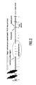
- a critical time period is the serration pulse region forming part of the vertical sync period wherein serration pulses occur which have no back porch region.
- Figure 2 it is shown the waveform of the CVBS signal without influence of airplane flutter and in particular the waveform of the CVBS signal during the beginning of the vertical sync period including the serration pulse region.
- the digital signal processing device 10 changes the gating from back porch to front porch during the serration pulse region. So, the serration pulse region is gated with three time-shifted horizontal sync pulses by taking the error signal from the front porch measurement. In the digital domain this can be done with high accuracy. So, the AGC loop stays closed all the time and can thus function with good performance.
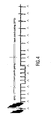
- Figure 4 shows the waveform of the CVBS signal under the occurrence of airplane flutter (80% AM, 80 Hz) and further showing the gaiting pulses indicated as upright arrows below the CVBS waveform, wherein front porch gating is carried out during the serration pulse region.
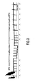
- Figure 5 shows more details of the timing instants for the sync and gating pulses with reference to Figure 4 .
- Figure 5 shows in more detail that during back porch gating the gating pulses occur a time distance ⁇ T1 after the occurrence of the sync pulses, whereas during the serration pulse region when front porch gating is carried out the gating pulses occur a time distance ⁇ T2 before the occurrence of the sync pulses. So, according to Figure 5 the gating pulses occur earlier by a time interval corresponding to the total time distance ⁇ T1 + ⁇ T2 to hit the front porch regions during the serration pulse region.
- Figure 6 shows an alternative method of changing from back porch gating to front porch gating wherein the gating pulses are delayed by a time interval ⁇ T3 behind the occurrence of the sync pulses to hit the next front porch region and the subsequent front porch regions during the serration pulse region. So, in the situation of Figure 6 , the gating pulses occur later by a time interval corresponding to the time distance ⁇ T3 - ⁇ T1 between the first back porch region and the next front porch region within the serration pulse region so as to change from back porch gating to front porch gating. With respect thereto, it should be added that apart from the different kind of changing from back porch gating to front porch gating, the situation of Figure 6 is the same as that of Figures 4 and 5 .
- the digital signal processing device 10 ( Figure 1 ) includes inter alia the function of an AGC detector.
Landscapes
- Engineering & Computer Science (AREA)
- Multimedia (AREA)
- Signal Processing (AREA)
- Television Receiver Circuits (AREA)
- Burglar Alarm Systems (AREA)
- Glass Compositions (AREA)
Claims (10)
- Erfassungsvorrichtung einer automatischen Verstärkungssteuerung (AGC) für Fernsehempfänger, welche Videobilder bestehend aus einer Vielzahl von horizontalen aufeinanderfolgend aufzubauenden Zeilen unter Verwendung von Taktimpulsen für AGC anzeigen, aufweisend- Mittel (2) zum Einspeisen eines CVBS-, Farb-Bild-Austastung-Synchron-, Signals, welches horizontale Synchronisierungsimpulse enthält, welche einen vorderen Schwarzschulterbereich und einen hinteren Schwarzschulterbereich besitzen und einmal pro horizontale Zeile während einer horizontalen Synchronisierungsperiode auftreten, wenn ein momentanes Videobild erzeugt wird, und weiter vertikale Synchronisierungsimpulse enthält, welche während einer vertikalen Synchronisierungsperiode vor der Erzeugung eines neuen Videobilds auftreten und Zackenimpulse enthalten, welche während eines Zackenimpulsbereichs auftreten, der Teil der vertikalen Synchronisierungsperiode ist, ,- Mittel (10) zum Erzeugen von Taktimpulsen, die eine Periode besitzen, welche gleich der Zeilenperiode der horizontalen Synchronisierungsimpulse ist, und- Mittel (10) zum Anpassen der Taktimpulse derart, dass sie während des horizontalen Schwarzschulterbereichs (ΔT1) bezüglich der horizontalen Synchronisierungsimpulsen auftreten,
gekennzeichnet durch- Mittel (10) zum Verschieben des Auftretens der Taktimpulse während des Zackenimpulsbereichs der vertikalen Synchronisierungsperiode, sodass die Taktimpulse ein Zeitintervall früher, welches dem Zeitabstand (ΔT1 + ΔT2) zwischen einem vorderen Schwarzschulterbereich und dem nächsten hinteren Schwarzschulterbereich entspricht, oder ein Zeitintervall später, welches dem Zeitabstand (ΔT3 - ΔT1) zwischen einem hinteren Schwarzschulterbereich und dem nächsten Vorderen Schwarzschulterbereich entspricht, auftreten. - Vorrichtung gemäß Anspruch 1, weiter gekennzeichnet durch- erste Mittel (10) zum Detektieren des Auftretens des hinteren Schwarzschulterbereichs der horizontalen Synchronisierungsimpulse, und- zweite Mittel (10) zum Detektieren des Auftretens des vorderen Schwarzschulterbereichs der horizontalen Synchronisierungsimpulse,- wobei die ersten und zweiten Erfassungsmittel (10) mit den Verschiebungsmitteln (10) gekoppelt sind, und wenigstens die ersten Erfassungsmittel (10) mit den Anpassungsmitteln (10) gekoppelt sind.
- Vorrichtung gemäß Anspruch 1 oder 2, dadurch gekennzeichnet, dass die Vorrichtung (10) eine digitale AGC-Erfassungsvorrichtung ist.
- Vorrichtung gemäß wenigstens einem der Ansprüche 1 bis 3, dadurch gekennzeichnet, dass die Vorrichtung (10) für analoge Fernsehempfänger vorgesehen ist.
- Vorrichtung gemäß wenigstens einem der Ansprüche 1 bis 4, wobei die Taktimpulserzeugungsmittel (10) eine PLL-Schaltung aufweisen.
- Vorrichtung gemäß Anspruch 5, wobei die PLL-Schaltung eine H-PLL-Schaltung ist, und die Taktimpulserzeugungsmittel (10) weiter eine V-Integrationseinrichtung aufweisen.
- Vorrichtung gemäß wenigstens einem der Ansprüche 1 bis 6, wobei die Taktimpulserzeugungsmittel (10) eine Synchronisierungsabkappungseinrichtung aufweisen.
- Verfahren zum Detektieren von AGC (automatische Verstärkungssteuerung) für Fernsehempfänger, die Videobilder, welche aus einer Vielzahl von horizontalen aufeinanderfolgend aufzubauenden Zeilen bestehen, unter Verwendung von Taktimpulsen für AGC anzeigen, aufweisend die Schritte:- Einspeisen eines CVBS-, Farb-Bild-Austastung-Synchron-, Signals, welches horizontale Synchronisierungspulse enthält, die einen vorderen Schwarzschulterbereich und einen hinteren Schwarzschulterbereich besitzen und einmal pro horizontaler Zeile während einer horizontalen Synchronisierungsperiode auftreten, wenn ein momentanes Videobild erzeugt wird, und weiter vertikale Synchronisierungsimpulse enthalten, die während einer vertikalen Synchronisierungsperiode vor der Erzeugung eines neuen Videobildes auftreten und Zackenimpulse enthalten, die während eines Zackenimpulsbereichs auftreten, der Teil der vertikalen Synchronisierungsperiode ist,- Erzeugen von Taktimpulsen, die eine Periode besitzen, die gleich der Zeilenperiode der horizontalen Synchronisierungsimpulse ist,- Anpassen der Taktimpulse derart, dass sie an dem hinteren Schwarzschulterbereich (ΔT1) relativ zu den horizontalen Synchronisierungsimpulsen auftreten,
gekennzeichnet durch den weiteren Schritt:- Verschieben des Auftretens der Taktimpulse während des im Zackenimpulsbereichs der vertikalen Synchronisierungsperiode, sodass die Taktimpulse ein Zeitintervall früher, welches dem Zeitabstand (ΔT1 + ΔT2) zwischen einem vorderen Schwarzschulterbereich und dem nächsten hinteren Schwarzschulterbereich entspricht, oder ein Zeitintervall später, welches dem Zeitabstand (ΔT3 - ΔT1) zwischen einem hinteren Schwarzschulterbereich und dem nächsten vorderen Schwarzschulterbereich entspricht, auftreten. - Verfahren gemäß Anspruch 8, dadurch gekennzeichnet, dass der letzte Schritt des Verschiebens des Auftretens der Taktimpulse während des Zackenimpulsbereichs im digitalen Bereich ausgeführt wird.
- Verfahren gemäß Anspruch 8 oder 9, dadurch gekennzeichnet, dass das Verfahren für analogen Fernsehempfang vorgesehen ist.
Priority Applications (1)
| Application Number | Priority Date | Filing Date | Title |
|---|---|---|---|
| EP03702843A EP1479228B1 (de) | 2002-02-09 | 2003-02-03 | Agc-detektor und verfahren zur agc-detektion |
Applications Claiming Priority (4)
| Application Number | Priority Date | Filing Date | Title |
|---|---|---|---|
| EP02002917 | 2002-02-09 | ||
| EP02002917 | 2002-02-09 | ||
| EP03702843A EP1479228B1 (de) | 2002-02-09 | 2003-02-03 | Agc-detektor und verfahren zur agc-detektion |
| PCT/IB2003/000399 WO2003067877A1 (en) | 2002-02-09 | 2003-02-03 | Agc detector and method for agc detecting |
Publications (2)
| Publication Number | Publication Date |
|---|---|
| EP1479228A1 EP1479228A1 (de) | 2004-11-24 |
| EP1479228B1 true EP1479228B1 (de) | 2009-09-23 |
Family
ID=27675612
Family Applications (1)
| Application Number | Title | Priority Date | Filing Date |
|---|---|---|---|
| EP03702843A Expired - Lifetime EP1479228B1 (de) | 2002-02-09 | 2003-02-03 | Agc-detektor und verfahren zur agc-detektion |
Country Status (8)
| Country | Link |
|---|---|
| US (1) | US7259799B2 (de) |
| EP (1) | EP1479228B1 (de) |
| JP (1) | JP2005517360A (de) |
| CN (1) | CN1274142C (de) |
| AT (1) | ATE443968T1 (de) |
| AU (1) | AU2003205960A1 (de) |
| DE (1) | DE60329372D1 (de) |
| WO (1) | WO2003067877A1 (de) |
Families Citing this family (15)
| Publication number | Priority date | Publication date | Assignee | Title |
|---|---|---|---|---|
| US8175562B2 (en) * | 2006-10-27 | 2012-05-08 | Agere Systems Inc. | Automatic gain control for enhanced bit error rate performance |
| TWI354981B (en) * | 2007-01-29 | 2011-12-21 | Qisda Corp | Method and related device of increasing efficiency |
| US8385867B2 (en) | 2009-06-29 | 2013-02-26 | Silicon Laboratories Inc. | Tracking filter for a television tuner |
| US8576343B2 (en) | 2009-06-29 | 2013-11-05 | Silicon Laboratories Inc. | Digital signal processor (DSP) architecture for a hybrid television tuner |
| US8228431B2 (en) | 2009-08-31 | 2012-07-24 | Silicon Laboratories Inc. | Digital phase lock loop configurable as a frequency estimator |
| US8433970B2 (en) | 2010-03-31 | 2013-04-30 | Silicon Laboratories Inc. | Techniques to control power consumption in an iterative decoder by control of node configurations |
| US8555131B2 (en) | 2010-03-31 | 2013-10-08 | Silicon Laboratories Inc. | Techniques to control power consumption in an iterative decoder by control of node configurations |
| US8341486B2 (en) | 2010-03-31 | 2012-12-25 | Silicon Laboratories Inc. | Reducing power consumption in an iterative decoder |
| US8237869B2 (en) | 2010-03-31 | 2012-08-07 | Silicon Laboratories Inc. | Multi-standard digital demodulator for TV signals broadcast over cable, satellite and terrestrial networks |
| JP5251926B2 (ja) * | 2010-06-16 | 2013-07-31 | セイコーエプソン株式会社 | 撮影装置およびタイミング制御回路 |
| US8346202B2 (en) | 2010-06-28 | 2013-01-01 | Silicon Laboratories Inc. | Digital intensive baseband chain of a receiver |
| US8837611B2 (en) | 2011-02-09 | 2014-09-16 | Silicon Laboratories Inc. | Memory-aided synchronization in a receiver |
| US8644370B2 (en) | 2012-01-25 | 2014-02-04 | Silicon Laboratories | Providing slope values for a demapper |
| US8451376B1 (en) * | 2012-04-24 | 2013-05-28 | Silicon Laboratories Inc. | Automatic gain control (AGC) for analog TV signals using feed-forward signal path delay |
| US8959274B2 (en) | 2012-09-06 | 2015-02-17 | Silicon Laboratories Inc. | Providing a serial download path to devices |
Family Cites Families (10)
| Publication number | Priority date | Publication date | Assignee | Title |
|---|---|---|---|---|
| US2796462A (en) * | 1952-03-19 | 1957-06-18 | Rca Corp | Automatic gain control circuits with hum compensation |
| US2938950A (en) * | 1954-01-08 | 1960-05-31 | Ferguson Radio Corp | Automatic gain control circuits for television signal amplifiers |
| US3531590A (en) * | 1966-12-05 | 1970-09-29 | Motorola Inc | Automatic gain control circuit |
| US3560648A (en) * | 1968-08-29 | 1971-02-02 | Bell Telephone Labor Inc | Sampled data automatic gain control circuit |
| NL169811C (nl) * | 1975-10-03 | 1982-08-16 | Philips Nv | Beeldregelsynchronisatieschakeling, alsmede televisieontvanger daarvan voorzien. |
| US4212032A (en) * | 1978-08-18 | 1980-07-08 | Rca Corporation | Synchronization and gain control circuit |
| US4216502A (en) * | 1978-08-18 | 1980-08-05 | Rca Corporation | Peak detector circuit |
| JPS5815377A (ja) * | 1981-07-21 | 1983-01-28 | Clarion Co Ltd | テレビジヨン信号受信機のagc方式 |
| JPS622783A (ja) * | 1985-06-28 | 1987-01-08 | Toshiba Corp | Agc回路 |
| US6188832B1 (en) * | 1997-05-07 | 2001-02-13 | Microvision Corp | Method and apparatus for modifications made to a video signal to inhibit the making of acceptable videotape recordings |
-
2003
- 2003-02-03 AU AU2003205960A patent/AU2003205960A1/en not_active Abandoned
- 2003-02-03 WO PCT/IB2003/000399 patent/WO2003067877A1/en not_active Ceased
- 2003-02-03 EP EP03702843A patent/EP1479228B1/de not_active Expired - Lifetime
- 2003-02-03 JP JP2003567088A patent/JP2005517360A/ja not_active Ceased
- 2003-02-03 AT AT03702843T patent/ATE443968T1/de not_active IP Right Cessation
- 2003-02-03 CN CN03803520.0A patent/CN1274142C/zh not_active Expired - Fee Related
- 2003-02-03 DE DE60329372T patent/DE60329372D1/de not_active Expired - Lifetime
- 2003-02-03 US US10/503,686 patent/US7259799B2/en not_active Expired - Fee Related
Also Published As
| Publication number | Publication date |
|---|---|
| DE60329372D1 (de) | 2009-11-05 |
| ATE443968T1 (de) | 2009-10-15 |
| US7259799B2 (en) | 2007-08-21 |
| AU2003205960A1 (en) | 2003-09-02 |
| CN1274142C (zh) | 2006-09-06 |
| US20050088367A1 (en) | 2005-04-28 |
| JP2005517360A (ja) | 2005-06-09 |
| CN1631036A (zh) | 2005-06-22 |
| EP1479228A1 (de) | 2004-11-24 |
| WO2003067877A1 (en) | 2003-08-14 |
Similar Documents
| Publication | Publication Date | Title |
|---|---|---|
| EP1479228B1 (de) | Agc-detektor und verfahren zur agc-detektion | |
| US4819098A (en) | Method and apparatus for clustering modifications made to a video signal to inhibit the making of acceptable videotape recordings | |
| US5251041A (en) | Method and apparatus for modifying a video signal to inhibit unauthorized videotape recording and subsequent reproduction thereof | |
| US20110002663A1 (en) | Method and apparatus for attenuating or eliminating at least a portion of color burst modifications to a video signal | |
| US20070242930A1 (en) | Method and apparatus for modifying a video signal or for providing a copy protection signal by adding selected negative going and positive going pulses | |
| US4963969A (en) | Automatic gain control device | |
| JP3662544B2 (ja) | テレビジョンシステム | |
| US6188832B1 (en) | Method and apparatus for modifications made to a video signal to inhibit the making of acceptable videotape recordings | |
| EP0899945B1 (de) | Verfahren und Vorrichtung zur Gewinnung von Zeilensynchronisations-Informationsposten aus einem Videosignal | |
| US7173668B2 (en) | Equilibrium based horizontal sync detector for video decoder | |
| US5568201A (en) | Clock signal generating apparatus | |
| EP0479610B1 (de) | Fernsehempfänger | |
| JPS5945276B2 (ja) | ドロツプアウト補償回路 | |
| US5309226A (en) | Means for cancelling ghost signals in response to the reception of a non-standard television video signal | |
| KR100447004B1 (ko) | 비디오신호처리방법및비디오신호처리장치 | |
| US5103477A (en) | Method and apparatus for descrambling a television signal | |
| JPS6161310B2 (de) | ||
| KR20100045518A (ko) | 개선된 재생성능을 가지는 티브이 세트를 사용한 복제 방지 또는 컨텐츠 제어 신호 합성 방법 및 장치 | |
| JP2993676B2 (ja) | テレビジョン受信機 | |
| JPH05336458A (ja) | テレビジョン受信機およびテレビジョン受信チューナ | |
| JPH0546186U (ja) | 文字放送再生装置 | |
| MXPA98009268A (en) | Method and apparatus for modifications made to a video signal to inhibit the production of acceptable records of vibrates | |
| HK1016391B (en) | Method and apparatus for modifications made to a video signal to inhibit the making of acceptable videotape recordings | |
| JPH0425296A (ja) | バーストフラグパルス生成方式 | |
| JPH05344475A (ja) | 垂直同期乱れ防止装置 |
Legal Events
| Date | Code | Title | Description |
|---|---|---|---|
| PUAI | Public reference made under article 153(3) epc to a published international application that has entered the european phase |
Free format text: ORIGINAL CODE: 0009012 |
|
| 17P | Request for examination filed |
Effective date: 20040909 |
|
| AK | Designated contracting states |
Kind code of ref document: A1 Designated state(s): AT BE BG CH CY CZ DE DK EE ES FI FR GB GR HU IE IT LI LU MC NL PT SE SI SK TR |
|
| AX | Request for extension of the european patent |
Extension state: AL LT LV MK RO |
|
| RAP1 | Party data changed (applicant data changed or rights of an application transferred) |
Owner name: PHILIPS INTELLECTUAL PROPERTY & STANDARDS GMBH Owner name: KONINKLIJKE PHILIPS ELECTRONICS N.V. |
|
| RAP1 | Party data changed (applicant data changed or rights of an application transferred) |
Owner name: NXP B.V. |
|
| GRAP | Despatch of communication of intention to grant a patent |
Free format text: ORIGINAL CODE: EPIDOSNIGR1 |
|
| GRAS | Grant fee paid |
Free format text: ORIGINAL CODE: EPIDOSNIGR3 |
|
| GRAA | (expected) grant |
Free format text: ORIGINAL CODE: 0009210 |
|
| AK | Designated contracting states |
Kind code of ref document: B1 Designated state(s): AT BE BG CH CY CZ DE DK EE ES FI FR GB GR HU IE IT LI LU MC NL PT SE SI SK TR |
|
| REG | Reference to a national code |
Ref country code: GB Ref legal event code: FG4D |
|
| REG | Reference to a national code |
Ref country code: CH Ref legal event code: EP |
|
| REG | Reference to a national code |
Ref country code: IE Ref legal event code: FG4D |
|
| REF | Corresponds to: |
Ref document number: 60329372 Country of ref document: DE Date of ref document: 20091105 Kind code of ref document: P |
|
| PG25 | Lapsed in a contracting state [announced via postgrant information from national office to epo] |
Ref country code: SE Free format text: LAPSE BECAUSE OF FAILURE TO SUBMIT A TRANSLATION OF THE DESCRIPTION OR TO PAY THE FEE WITHIN THE PRESCRIBED TIME-LIMIT Effective date: 20090923 Ref country code: FI Free format text: LAPSE BECAUSE OF FAILURE TO SUBMIT A TRANSLATION OF THE DESCRIPTION OR TO PAY THE FEE WITHIN THE PRESCRIBED TIME-LIMIT Effective date: 20090923 |
|
| PG25 | Lapsed in a contracting state [announced via postgrant information from national office to epo] |
Ref country code: SI Free format text: LAPSE BECAUSE OF FAILURE TO SUBMIT A TRANSLATION OF THE DESCRIPTION OR TO PAY THE FEE WITHIN THE PRESCRIBED TIME-LIMIT Effective date: 20090923 |
|
| NLV1 | Nl: lapsed or annulled due to failure to fulfill the requirements of art. 29p and 29m of the patents act | ||
| PG25 | Lapsed in a contracting state [announced via postgrant information from national office to epo] |
Ref country code: CY Free format text: LAPSE BECAUSE OF FAILURE TO SUBMIT A TRANSLATION OF THE DESCRIPTION OR TO PAY THE FEE WITHIN THE PRESCRIBED TIME-LIMIT Effective date: 20090923 |
|
| PG25 | Lapsed in a contracting state [announced via postgrant information from national office to epo] |
Ref country code: ES Free format text: LAPSE BECAUSE OF FAILURE TO SUBMIT A TRANSLATION OF THE DESCRIPTION OR TO PAY THE FEE WITHIN THE PRESCRIBED TIME-LIMIT Effective date: 20100103 Ref country code: PT Free format text: LAPSE BECAUSE OF FAILURE TO SUBMIT A TRANSLATION OF THE DESCRIPTION OR TO PAY THE FEE WITHIN THE PRESCRIBED TIME-LIMIT Effective date: 20100125 Ref country code: EE Free format text: LAPSE BECAUSE OF FAILURE TO SUBMIT A TRANSLATION OF THE DESCRIPTION OR TO PAY THE FEE WITHIN THE PRESCRIBED TIME-LIMIT Effective date: 20090923 Ref country code: CZ Free format text: LAPSE BECAUSE OF FAILURE TO SUBMIT A TRANSLATION OF THE DESCRIPTION OR TO PAY THE FEE WITHIN THE PRESCRIBED TIME-LIMIT Effective date: 20090923 |
|
| PG25 | Lapsed in a contracting state [announced via postgrant information from national office to epo] |
Ref country code: SK Free format text: LAPSE BECAUSE OF FAILURE TO SUBMIT A TRANSLATION OF THE DESCRIPTION OR TO PAY THE FEE WITHIN THE PRESCRIBED TIME-LIMIT Effective date: 20090923 |
|
| PG25 | Lapsed in a contracting state [announced via postgrant information from national office to epo] |
Ref country code: AT Free format text: LAPSE BECAUSE OF FAILURE TO SUBMIT A TRANSLATION OF THE DESCRIPTION OR TO PAY THE FEE WITHIN THE PRESCRIBED TIME-LIMIT Effective date: 20090923 Ref country code: BE Free format text: LAPSE BECAUSE OF FAILURE TO SUBMIT A TRANSLATION OF THE DESCRIPTION OR TO PAY THE FEE WITHIN THE PRESCRIBED TIME-LIMIT Effective date: 20090923 |
|
| PG25 | Lapsed in a contracting state [announced via postgrant information from national office to epo] |
Ref country code: DK Free format text: LAPSE BECAUSE OF FAILURE TO SUBMIT A TRANSLATION OF THE DESCRIPTION OR TO PAY THE FEE WITHIN THE PRESCRIBED TIME-LIMIT Effective date: 20090923 Ref country code: NL Free format text: LAPSE BECAUSE OF FAILURE TO SUBMIT A TRANSLATION OF THE DESCRIPTION OR TO PAY THE FEE WITHIN THE PRESCRIBED TIME-LIMIT Effective date: 20090923 |
|
| PLBE | No opposition filed within time limit |
Free format text: ORIGINAL CODE: 0009261 |
|
| STAA | Information on the status of an ep patent application or granted ep patent |
Free format text: STATUS: NO OPPOSITION FILED WITHIN TIME LIMIT |
|
| 26N | No opposition filed |
Effective date: 20100624 |
|
| REG | Reference to a national code |
Ref country code: CH Ref legal event code: PL |
|
| PG25 | Lapsed in a contracting state [announced via postgrant information from national office to epo] |
Ref country code: MC Free format text: LAPSE BECAUSE OF NON-PAYMENT OF DUE FEES Effective date: 20100301 Ref country code: LI Free format text: LAPSE BECAUSE OF NON-PAYMENT OF DUE FEES Effective date: 20100228 Ref country code: CH Free format text: LAPSE BECAUSE OF NON-PAYMENT OF DUE FEES Effective date: 20100228 Ref country code: GR Free format text: LAPSE BECAUSE OF FAILURE TO SUBMIT A TRANSLATION OF THE DESCRIPTION OR TO PAY THE FEE WITHIN THE PRESCRIBED TIME-LIMIT Effective date: 20091224 |
|
| PG25 | Lapsed in a contracting state [announced via postgrant information from national office to epo] |
Ref country code: IE Free format text: LAPSE BECAUSE OF NON-PAYMENT OF DUE FEES Effective date: 20100203 |
|
| PG25 | Lapsed in a contracting state [announced via postgrant information from national office to epo] |
Ref country code: IT Free format text: LAPSE BECAUSE OF FAILURE TO SUBMIT A TRANSLATION OF THE DESCRIPTION OR TO PAY THE FEE WITHIN THE PRESCRIBED TIME-LIMIT Effective date: 20090923 |
|
| PG25 | Lapsed in a contracting state [announced via postgrant information from national office to epo] |
Ref country code: LU Free format text: LAPSE BECAUSE OF NON-PAYMENT OF DUE FEES Effective date: 20100203 Ref country code: HU Free format text: LAPSE BECAUSE OF FAILURE TO SUBMIT A TRANSLATION OF THE DESCRIPTION OR TO PAY THE FEE WITHIN THE PRESCRIBED TIME-LIMIT Effective date: 20100324 Ref country code: BG Free format text: LAPSE BECAUSE OF FAILURE TO SUBMIT A TRANSLATION OF THE DESCRIPTION OR TO PAY THE FEE WITHIN THE PRESCRIBED TIME-LIMIT Effective date: 20090923 |
|
| PG25 | Lapsed in a contracting state [announced via postgrant information from national office to epo] |
Ref country code: TR Free format text: LAPSE BECAUSE OF FAILURE TO SUBMIT A TRANSLATION OF THE DESCRIPTION OR TO PAY THE FEE WITHIN THE PRESCRIBED TIME-LIMIT Effective date: 20090923 |
|
| REG | Reference to a national code |
Ref country code: GB Ref legal event code: 732E Free format text: REGISTERED BETWEEN 20130606 AND 20130612 |
|
| REG | Reference to a national code |
Ref country code: FR Ref legal event code: PLFP Year of fee payment: 13 |
|
| REG | Reference to a national code |
Ref country code: FR Ref legal event code: PLFP Year of fee payment: 14 |
|
| REG | Reference to a national code |
Ref country code: FR Ref legal event code: PLFP Year of fee payment: 15 |
|
| REG | Reference to a national code |
Ref country code: FR Ref legal event code: PLFP Year of fee payment: 16 |
|
| PGFP | Annual fee paid to national office [announced via postgrant information from national office to epo] |
Ref country code: GB Payment date: 20200123 Year of fee payment: 18 Ref country code: DE Payment date: 20200121 Year of fee payment: 18 |
|
| PGFP | Annual fee paid to national office [announced via postgrant information from national office to epo] |
Ref country code: FR Payment date: 20200122 Year of fee payment: 18 |
|
| REG | Reference to a national code |
Ref country code: DE Ref legal event code: R119 Ref document number: 60329372 Country of ref document: DE |
|
| GBPC | Gb: european patent ceased through non-payment of renewal fee |
Effective date: 20210203 |
|
| PG25 | Lapsed in a contracting state [announced via postgrant information from national office to epo] |
Ref country code: DE Free format text: LAPSE BECAUSE OF NON-PAYMENT OF DUE FEES Effective date: 20210901 Ref country code: FR Free format text: LAPSE BECAUSE OF NON-PAYMENT OF DUE FEES Effective date: 20210228 Ref country code: GB Free format text: LAPSE BECAUSE OF NON-PAYMENT OF DUE FEES Effective date: 20210203 |