EP1479317A1 - Dämpfungs- und Einzugsvorrichtung - Google Patents
Dämpfungs- und Einzugsvorrichtung Download PDFInfo
- Publication number
- EP1479317A1 EP1479317A1 EP04008819A EP04008819A EP1479317A1 EP 1479317 A1 EP1479317 A1 EP 1479317A1 EP 04008819 A EP04008819 A EP 04008819A EP 04008819 A EP04008819 A EP 04008819A EP 1479317 A1 EP1479317 A1 EP 1479317A1
- Authority
- EP
- European Patent Office
- Prior art keywords
- damping
- housing
- driver
- retraction device
- web
- Prior art date
- Legal status (The legal status is an assumption and is not a legal conclusion. Google has not performed a legal analysis and makes no representation as to the accuracy of the status listed.)
- Withdrawn
Links
- 238000013016 damping Methods 0.000 title claims description 51
- 238000000034 method Methods 0.000 claims description 4
- IHQKEDIOMGYHEB-UHFFFAOYSA-M sodium dimethylarsinate Chemical class [Na+].C[As](C)([O-])=O IHQKEDIOMGYHEB-UHFFFAOYSA-M 0.000 claims description 3
- 230000005540 biological transmission Effects 0.000 abstract 1
- 238000004146 energy storage Methods 0.000 abstract 1
- 238000001746 injection moulding Methods 0.000 description 2
- 239000012190 activator Substances 0.000 description 1
- 238000010276 construction Methods 0.000 description 1
- 238000009434 installation Methods 0.000 description 1
- 239000000243 solution Substances 0.000 description 1
Images







Classifications
-
- A—HUMAN NECESSITIES
- A47—FURNITURE; DOMESTIC ARTICLES OR APPLIANCES; COFFEE MILLS; SPICE MILLS; SUCTION CLEANERS IN GENERAL
- A47B—TABLES; DESKS; OFFICE FURNITURE; CABINETS; DRAWERS; GENERAL DETAILS OF FURNITURE
- A47B88/00—Drawers for tables, cabinets or like furniture; Guides for drawers
- A47B88/40—Sliding drawers; Slides or guides therefor
- A47B88/42—Vertically-oriented drawers, i.e. drawers where the height exceeds the width
-
- A—HUMAN NECESSITIES
- A47—FURNITURE; DOMESTIC ARTICLES OR APPLIANCES; COFFEE MILLS; SPICE MILLS; SUCTION CLEANERS IN GENERAL
- A47B—TABLES; DESKS; OFFICE FURNITURE; CABINETS; DRAWERS; GENERAL DETAILS OF FURNITURE
- A47B88/00—Drawers for tables, cabinets or like furniture; Guides for drawers
- A47B88/40—Sliding drawers; Slides or guides therefor
- A47B88/453—Actuated drawers
- A47B88/46—Actuated drawers operated by mechanically-stored energy, e.g. by springs
- A47B88/467—Actuated drawers operated by mechanically-stored energy, e.g. by springs self-closing
-
- E—FIXED CONSTRUCTIONS
- E05—LOCKS; KEYS; WINDOW OR DOOR FITTINGS; SAFES
- E05F—DEVICES FOR MOVING WINGS INTO OPEN OR CLOSED POSITION; CHECKS FOR WINGS; WING FITTINGS NOT OTHERWISE PROVIDED FOR, CONCERNED WITH THE FUNCTIONING OF THE WING
- E05F1/00—Closers or openers for wings, not otherwise provided for in this subclass
- E05F1/08—Closers or openers for wings, not otherwise provided for in this subclass spring-actuated, e.g. for horizontally sliding wings
- E05F1/16—Closers or openers for wings, not otherwise provided for in this subclass spring-actuated, e.g. for horizontally sliding wings for sliding wings
-
- E—FIXED CONSTRUCTIONS
- E05—LOCKS; KEYS; WINDOW OR DOOR FITTINGS; SAFES
- E05F—DEVICES FOR MOVING WINGS INTO OPEN OR CLOSED POSITION; CHECKS FOR WINGS; WING FITTINGS NOT OTHERWISE PROVIDED FOR, CONCERNED WITH THE FUNCTIONING OF THE WING
- E05F5/00—Braking devices, e.g. checks; Stops; Buffers
- E05F5/003—Braking devices, e.g. checks; Stops; Buffers for sliding wings
-
- E—FIXED CONSTRUCTIONS
- E05—LOCKS; KEYS; WINDOW OR DOOR FITTINGS; SAFES
- E05Y—INDEXING SCHEME ASSOCIATED WITH SUBCLASSES E05D AND E05F, RELATING TO CONSTRUCTION ELEMENTS, ELECTRIC CONTROL, POWER SUPPLY, POWER SIGNAL OR TRANSMISSION, USER INTERFACES, MOUNTING OR COUPLING, DETAILS, ACCESSORIES, AUXILIARY OPERATIONS NOT OTHERWISE PROVIDED FOR, APPLICATION THEREOF
- E05Y2201/00—Constructional elements; Accessories therefor
- E05Y2201/10—Covers; Housings
-
- E—FIXED CONSTRUCTIONS
- E05—LOCKS; KEYS; WINDOW OR DOOR FITTINGS; SAFES
- E05Y—INDEXING SCHEME ASSOCIATED WITH SUBCLASSES E05D AND E05F, RELATING TO CONSTRUCTION ELEMENTS, ELECTRIC CONTROL, POWER SUPPLY, POWER SIGNAL OR TRANSMISSION, USER INTERFACES, MOUNTING OR COUPLING, DETAILS, ACCESSORIES, AUXILIARY OPERATIONS NOT OTHERWISE PROVIDED FOR, APPLICATION THEREOF
- E05Y2800/00—Details, accessories and auxiliary operations not otherwise provided for
- E05Y2800/26—Form or shape
- E05Y2800/30—Form or shape inclined, angled
-
- E—FIXED CONSTRUCTIONS
- E05—LOCKS; KEYS; WINDOW OR DOOR FITTINGS; SAFES
- E05Y—INDEXING SCHEME ASSOCIATED WITH SUBCLASSES E05D AND E05F, RELATING TO CONSTRUCTION ELEMENTS, ELECTRIC CONTROL, POWER SUPPLY, POWER SIGNAL OR TRANSMISSION, USER INTERFACES, MOUNTING OR COUPLING, DETAILS, ACCESSORIES, AUXILIARY OPERATIONS NOT OTHERWISE PROVIDED FOR, APPLICATION THEREOF
- E05Y2900/00—Application of doors, windows, wings or fittings thereof
- E05Y2900/20—Application of doors, windows, wings or fittings thereof for furniture, e.g. cabinets
Definitions
- the present invention relates to a damping and retraction device for Sliding elements in the form of high pull-outs with an energy accumulator that when Opening process of a sliding element tensioned and its stored force used as closing aid in the final closed position during the closing process and with a damper, by means of which shortly before reaching the final The closed position counteracts the direction of the closing forces and the Closing movement damping counterforce is applied, and in which the energy accumulator and the damper is arranged in a common, elongated housing are, which is attached to a movable element.
- the damping and retraction device in question is in many versions known.
- the sliding elements are, for example, drawers from Cupboards, sliding doors for cupboards or sliding doors as room dividers.
- the damping and retraction device in question is also called self-retraction referred to, since it is to be ensured that the sliding element is reliable is pulled into the closed position, whereby the damper should ensure that the sliding element is pulled into the closed position at low speed, so that there is no disturbing noise when the sliding element against you Stop moves.
- the previously known damping and retraction devices are for drawers designed as one above the other for high furniture be used in it.
- the height and masses of these drawers including the objects stored in it are relatively small.
- the present invention has for its object a damping and Feeder of the type described in more detail in a structurally simple Form so that they can also be used for high pull-outs with a relatively high mass can be used, it should be ensured that it works properly.
- the task is solved by pivoting a driver in the housing slidably arranged and which is connected to the energy accumulator, and that the driver is provided with a boom that has a slot in the housing penetrates and has a guide web at its free end, and that the Driver on the side opposite the guide bar a locking bar and a release bar parallel and at a distance from it having.
- the energy accumulator and the damper are now for the masses to be moved aligned.
- the housing is designed so that the forces to be applied are safe can be removed.
- the damping and retraction device is a unit that is in a suitable place can be mounted in the area of the guide rails.
- the boom in connection with the guide bar ensures safe guidance of the driver when the energy accumulator when the sliding element is extended excited and even when he pushed the sliding element in the course of relaxation Close position pulls.
- the locking bar ensures that the tensioned State of the energy accumulator of the driver is locked in the position, while the unlocking bar releases this lock, so that the energy accumulator the sliding element pulls into the closed position.
- the driver is locked in a structurally simple manner, when in the tensioned state of the energy accumulator the locking bar of the driver pulls into a recess of the housing, and that during the extension movement of the sliding element on the webs opposite the guide web slide the housing.
- the guide web and the locking recess lie on the opposite one another Narrow sides of the case.
- this control cam causes the energy accumulator is excited.
- the control cam reaches into the space between the locking web and the unlocking bar.
- the driver is pivoted so that the control cam is then disengaged comes with the driver.
- the driver is pivoted in the opposite direction and the Steuermokken comes back into engagement with the driver. It can then be the energy store become effective to pull the sliding element into the end position. Doing so the movement slowed down by the damper.
- Housing consists of two housing halves, which are connected by a film hinge connected or locked together.
- the components can then be inserted into a housing half, and the second housing half can then be connected to the first housing half be locked.
- the housing consists of two Housing halves is formed, which are connected to each other only by locking are.
- the connection via a film hinge has the advantage that the housing halves are captively connected.
- At least one housing half is triangular or has a trapezoidal cross section, so that the housing as a whole in Cross section is conical.
- the second part is then expedient, which can be viewed as component-free, the housing half with the triangular or trapezoidal cross section.
- the housing would be visible at least in the extended position. It is therefore provided that on the sliding part and / or on the extendable guide rail an apron encompassing the housing is fixed.
- This apron is adapted to the cross-sectional shape of the housing or the housing to the cross-sectional shape and consequently it contacts the walls.
- this apron is a double apron designed, the two receiving spaces for the housing via a Are connected to each other. In practice, there is always only one Apron needed.
- the driver is with a connection surface for a tab or a head of the Damper equipped so that a tab of the damper through a connecting element can be connected to the driver.
- the driver is also equipped with a hook to help with training of the lift mechanism as a tension spring to hang it in at one end.
- the housing is provided on the inside with a pin to the other end of the Hang the tension spring in it.
- This pin is expediently arranged in the housing half, which on the Sliding element or the extendable guide rail is present.
- the housing is also provided with a screw-in pin to ensure that end of the damper facing away from the driver by means of a Connect screw.
- the housing is in one piece is formed and provided on the broad sides with openings so that the components the damping and retraction device can be used. You can these openings at least in the area of the energy accumulator and the damper be provided on the opposite broad sides of the housing so that it Area has an S-shaped cross section.
- the area assigned to the driver could be one in the basic profile C-shaped cross section.
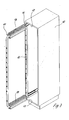
- FIG 1 shows a cabinet 10 with a retractable and extendable sliding element 11, wherein the cabinet 10 is designed as a pull-out, d. that is, the height is relatively large.
- the top shelf 12 and the bottom shelf 13 face each other Surfaces with generally known guide rails not explained in detail 14, 15 provided.
- the sliding element 11 is also equipped with corresponding guide rails, so that the sliding element 11 is movable.
- the sliding element 11 is provided with a support frame, the two at a distance has mutually extending vertical support rods 16 which provide rows of holes are to hang containers.
- the front of the sliding element 11 is equipped with an aperture 17 so that the cabinet 11 with the sliding element 11 also inserted on the front is completely closed.
- FIG. 2 shows the cabinet 10 according to FIG. 1, but with the cover removed Aperture 17 so that the rows of holes are visible.
- the holes in the rows of holes are keyhole-shaped can be designed so that corresponding bolts having a head in the vertical mounting rails can be attached.
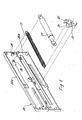
- the figure also shows 2 that the upper and lower sides of the support frame 16 two double aprons 18, 19 are associated with the protection of a damping and explained in more detail Serve feed device.
- the double aprons are set so that the upper double apron 18 two chambers open upwards and the lower double apron 19 has two chambers open downwards.
- the double aprons 18, 19 are in one opposite the embodiment according to FIG. 2 assembled by 90 °, so that the two chambers are open to the side.
- FIG 4 shows that in the right chamber of the double apron as shown 18 a damping and retraction device is used, which is even closer is explained.
- the damping and retraction device is in a housing 20 mounted, which consists of the two housing halves 20a and 20b.
- the housing half 20a facing the support rods 16 has a square one Cross-section, while the housing half 20b facing away from the support frame 16 has a has triangular cross section.
- the two chambers of the double apron 18 are connected by a central web 21.
- the housing halves 20a, 20b and the double aprons 18, 19 are made of made of a plastic.
- a force accumulator in the form of a tension spring 23 is suspended on the driver 22.
- the other end of the tension spring 23 is hooked onto an extension of the housing half 20a.
- the driver 22 faces the upper surface of the housing 20 before, because on this side with a transverse locking crossbar 24 and with a parallel and spaced unlocking web 25 is equipped.
- On the upper side is the housing for movability of the driver 22 provided with a slot.
- the housing 20 is also provided with a slot on the lower side, since the Driver 22 also penetrates the lower side of the housing 20.
- the driver 22 is equipped on the lower side with a guide web 26, which is perpendicular to the plane of the driver 22, so that it the lower Reaches behind the slit-defining edge.
- FIG. 6 shows that the two housing halves 20a and 20b of the housing 20th are connected by a film hinge so that the two housing parts are captively connected.
- the damping and retraction device too is also equipped with a damper 27, for example in the form of a gas spring, around the sliding element 11 braked by the action of the tensioned tension spring 23 to pull into the end position.
- the tension spring 23 is connected to a pin 28 the end opposite the driver 22 hooked.
- the damper 27 is connected to the driver 22, for example by a screw connected.
- the opposite end is pushed onto a further pin 29, the position of the damper 27 by a screw, not shown is secured.
- Figures 7 and 8 show the damping and retraction device in the assembled Status.
- FIG. 7 is a view of the housing half facing away from the support rods 16 20b directed. The figure shows that the housing half 20b has a longitudinal slot, that in the assembled state through the adjacent wall of the double apron 18 or 19 is covered.
- Figure 8 is with a view of the back, i. H. the facing the support rods 16 Side directed.
- a Slot provided, which is penetrated by the guide web 26 of the driver 22 is.
- Figure 9 shows that the guide web 26 of the driver 22 also one inwards engage behind the web or the lower walls of the housing 20 can.
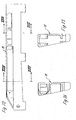
- Figures 10-13 show the driver 22 in four different positions.
- the Carrier has the locking web on the side assigned to the guide rails 14, 15 24 and the release bar 25.
- a bore 30 is provided directly under the unlocking web 25, around which Damper 27 to connect.
- the driver 22 is hook-shaped, to hook the tension spring 23. Extends from the locking web 24 a central web on which the guide web 26 is integrally formed.
- the driver 22 is off a plastic made by injection molding.
- FIG. 14 shows the upper fitting 14, which in the exemplary embodiment shown consists of three guide rails. As the figure still shows the double apron 18 is connected to the guide rail 14 by screws.
- the damping and retraction device is then located in a chamber of the double apron 18 31st
- FIG. 15 shows the housing 20, the driver 22, the tension spring 23 and the Damper 27 in an exploded view.
- the figure clearly shows that the driver 22 is provided with a semicircular recess in which the head of the extendable rod of the damper 27 engages. The fuse done by a screw.
- the damper 27 is identical in construction to the head Provide foot so that it can be pushed onto the pin 29. By The screw is then secured.
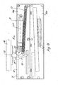
- Figure 16 shows the damping and retraction device with the folded down Housing part 20b.
- a slot 32 is provided in the upper wall of the housing half 20a the driver 22 slides.
- a Fixed control cam 33 which is also referred to as an activator could, since it is in the space between the locking web 24 and the unlocking web 25 engages.
- FIG. 16 shows the damping and retraction device 31 in the closed position of the sliding element 11.
- the tension spring 23 is untensioned or just slightly excited. Is by the extension movement of the sliding element 11 moves the housing 20 to the right as shown, the tension spring 23 excited.
- the piston rod of the damper 27 extends.
- a recess 34 is also provided in the upper wall of the housing half 20a, into which the slot 32 opens.
- the recess 34 is designed so that the locking web 24 is immersed therein, as shown in FIG. 17. In this position can move the housing or the damping and retraction device 31 be without the tension spring 23 is tensioned. The driver 22 then comes out of the area of the control cam 33.
- FIG. 17 shows that when the sliding element 11 is retracted in the direction of arrow B in a certain position the unlocking web 25 of the driver 22 on the Control cam 33 hits, whereby the locking web 24 out of the recess 34 is pivoted out, so that now the tensioned tension spring 23 relaxes and thereby pulls the sliding element 11 into the end position.
- FIGS. 18 and 19 each show the damping and retraction device 31 from the top, but in a rotated position.
- Figure 19 shows the recess 34 into which the locking web 24 is pressed when extending the sliding element 11.
- Figure 20 shows that the lower sides of the housing halves 20a, 20b partially jump inwards and that the guide web 26 of the driver 22 in this area is arranged.
- Figure 21 shows that the damping and retraction device 31 on the web the double apron 18 is present.
- FIGS. 22-24 show a housing 35 which is in one piece. It has to be that way be designed so that it is open at the sides to the driver 22, the Tension spring 23 and the damper 27 can be used therein.
- Figure 23 shows that the housing 35 outside the range of motion of the Driver 22 is designed C-shaped in the basic cross section.
- the housing In the movement area of the driver 23, the housing is designed in an S-shape. Also this housing is made of plastic by injection molding.
- the function of the damping and retraction device 31 corresponds to the previous one Solution.
- the guide of the driver 22 is extremely precise so that the Function is ensured. It is also essential that the driver 22 on the upper and bottom side is guided. This is done according to the embodiment through the locking bar 24 and the unlocking bar 25 and by the Guide bridge 26.
Landscapes
- Engineering & Computer Science (AREA)
- Mechanical Engineering (AREA)
- Drawers Of Furniture (AREA)
- Fluid-Damping Devices (AREA)
Abstract
Description
- Figur 1
- einen Schrank in Form eines Hochauszuges im perspektivischer Darstellung mit ausgefahrenem Schiebeelement,
- Figur 2
- eine der Figur 1 entsprechende Darstellung, jedoch ohne Blende,
- Figur 3
- eine der Figur 2 entsprechende Darstellung, jedoch in einer weiteren Ausführungsform,
- Figur 4
- die Ausführung gemäß der Figur 2 in einer Schnittdarstellung,
- Figur 5
- die Ausführung nach der Figur 2, jedoch mit einem Schnitt durch die Dämpfungs- und Einzugsvorrichtung,
- Figur 6
- die Dämpfungs- und Einzugsvorrichtung in einer sprengbildlichen Darstellung,
- Figur 7
- die Dämpfungs- und Einzugsvorrichtung im montierten Zustand in einer perspektivischen Darstellung,
- Figur 8
- die Dämpfungs- und Einzugsvorrichtung in einer perspektivischen Darstellung, jedoch in einer um 180° gedrehten Stellung,
- Figur 9
- einen Schnitt längs der Linie IX-IX in der Figur 7,
- Figuren 10 - 13
- den Mitnehmer der Dämpfungs- und Einzugsvorrichtung in vier verschiedenen Stellungen,
- Figur 14
- die Führungsschiene sowie die Dämpfungs- und Einzugsvorrichtung in einer sprengbildlichen Darstellung,
- Figur 15
- die Dämpfungs- und Einzugsvorrichtung in einer sprengbildlichen Darstellung,
- Figur 16
- die Dämpfungs- und Einzugsvorrichtung in einer Seitenansicht mit aufgeklapptem Gehäuse in der Schließstellung des Schiebeelementes,
- Figur 17
- eine der Figur 16 entsprechende Darstellung, jedoch die Dämpfungs- und Einzugsvorrichtung in der ausgefahrenen Stellung des Schiebeelementes zeigend,
- Figuren 18 u. 19
- die Dämpfungs- und Einzugsvorrichtung in zwei verschiedenen Stellungen,
- Figur 20
- einen Schnitt längs der Linie XX-XX in der Figur 19 zeigend,
- Figur 21
- die Führungsschiene mit einer Schürze und die Dämpfungs- und Einzugsvorrichtung in einer perspektivischen Darstellung,
- Figur 22
- das Gehäuse der Dämpfungs- und Einzugsvorrichtung zeigend,
- Figur 23
- einen Schnitt längs der Linie XXIII-XXIII in der Figur 22,
- Figur 24
- einen Schnitt längs der Linie XXIV-XXIV in der Figur 22.
Claims (13)
- Dämpfungs- und Einzugsvorrichtung (31) für Schiebeelemente (11), die in Führungsschienen (14, 15) geführt sind, mit einem Kraftspeicher (23), der beim Öffnungsvorgang eines Schiebeelementes (11) gespannt und dessen gespeicherte Kraft beim Schließvorgang als Einzugshilfe in die endgültige Schließstellung genutzt wird, und mit einem Dämpfer (27), mittels dessen kurz vor Erreichen der endgültigen Schließstellung eine der Richtung der Schließkräfte entgegenwirkende und die Schließbewegung dämpfende Gegenkraft aufgebracht wird, und der Kraftspeicher (23) und der Dämpfer (27) in einem gemeinsamen, langgestreckten Gehäuse (20) angeordnet sind, welches an einem verfahrbaren Element befestigt ist, dadurch gekennzeichnet, daß in dem Gehäuse (20) ein Mitnehmer (22) schwenk- und verschiebbar angeordnet und der mit dem Kraftspeicher (23) verbunden ist, und daß der Mitnehmer mit einem Ausleger (22) versehen ist, der einen Schlitz des Gehäuses (20) durchdringt, und an seinem freien Ende einen Führungssteg (26) aufweist, und daß der Mitnehmer (22) an der dem Führungssteg (26) gegenüber liegenden Seite einen Verriegelungssteg (24) und einen dazu parallel und im Abstand stehenden Entriegelungssteg (25) aufweist.
- Dämpfungs- und Einzugsvorrichtung nach Anspruch 1, dadurch gekennzeichnet, daß im gespannten Zustand der Kraftspeicher (23) den Verriegelungssteg (24) des Mitnehmers (22) in eine Ausnehmung (34) des Gehäuses (20) zieht und daß bei der Ausfahrbewegung des Schiebeelementes die dem Führungssteg (26) gegenüber liegenden Stege (24, 25) auf dem Gehäuse (20) gleiten.
- Dämpfungs- und Einzugsvorrichtung nach Anspruch 1 oder 2, dadurch gekennzeichnet, daß an einem ortsfesten Bauteil des Schiebeelementes oder des Beschlages ein fester Steuernocken (33) für den Mitnehmer (22) vorgesehen ist.
- Dämpfungs- und Einzugsvorrichtung nach Anspruch 1, dadurch gekennzeichnet, daß das Gehäuse (20) aus zwei Gehäusehälften (20a, 20b) besteht, die durch ein Filmscharnier miteinander verbunden und miteinander verrastet sind.
- Dämpfungs- und Einzugsvorrichtung nach Anspruch 1, dadurch gekennzeichnet, daß das Gehäuse (20) aus zwei Gehäusehälften (20a, 20b) besteht, die ausschließlich miteinander verrastet sind.
- Dämpfungs- und Einzugsvorrichtung nach einem oder mehreren der vorhergehenden Ansprüche 1-5, dadurch gekennzeichnet, daß das Gehäuse (20) einen konischen Querschnitt aufweist, und daß zumindest eine Gehäusehälfte einen dreieckigen oder trapezförmigen Querschnitt aufweist.
- Dämpfungs- und Einzugsvorrichtung nach einem oder mehreren der vorhergehenden Ansprüche 1-6, dadurch gekennzeichnet, daß am Schiebeteil (11) und/oder an einer ausfahrbaren Führungsschiene (14, 15) eine die Dämpfungsund Einzugsvorrichtung (31) umgebende Schürze (18, 19) festgelegt ist.
- Dämpfungs- und Einzugsvorrichtung nach Anspruch 7, dadurch gekennzeichnet, daß jede Schürze als Doppelschürze (18, 19) ausgebildet ist, und daß die beiden Kammern durch einen Mittelsteg miteinander verbunden sind.
- Dämpfungs- und Einzugsvorrichtung nach Anspruch 1, dadurch gekennzeichnet, daß der Mitnehmer (22) mit einer Anschlußfläche für eine Lasche oder einen Kopf des Dämpfers (27) ausgestattet ist.
- Dämpfungs- und Einzugsvorrichtung nach Anspruch 1, dadurch gekennzeichnet, daß der Mitnehmer (22) einen Haken zum Einhängen des Kraftspeichers (23) aufweist.
- Dämpfungs- und Einzugsvorrichtung nach einem oder mehreren der vorhergehenden Ansprüche 1-10, dadurch gekennzeichnet, daß das Gehäuse (22) innenseitig mit Zapfen (28, 29) zur Festlegung des Kraftspeichers (23) und des Dämpfers (27) ausgestattet ist.
- Dämpfungs- und Einzugsvorrichtung nach Anspruch 1, dadurch gekennzeichnet, daß das Gehäuse (35) einstückig ausgebildet ist, und daß an den Breitseiten Öffnungen vorgesehen sind.
- Dämpfungs- und Einzugsvorrichtung nach Anspruch 12, dadurch gekennzeichnet, daß das Gehäuse im Bewegungsbereich des Mitnehmers einen S-förmigen und im Bereich außerhalb des Bewegungsbereiches des Mitnehmers (22) einen C-förmigen Grundquerschnitt aufweist.
Applications Claiming Priority (2)
| Application Number | Priority Date | Filing Date | Title |
|---|---|---|---|
| DE20308217U DE20308217U1 (de) | 2003-05-22 | 2003-05-22 | Dämpfungs- und Einzugsvorrichtung |
| DE20308217U | 2003-05-22 |
Publications (1)
| Publication Number | Publication Date |
|---|---|
| EP1479317A1 true EP1479317A1 (de) | 2004-11-24 |
Family
ID=27675462
Family Applications (1)
| Application Number | Title | Priority Date | Filing Date |
|---|---|---|---|
| EP04008819A Withdrawn EP1479317A1 (de) | 2003-05-22 | 2004-04-14 | Dämpfungs- und Einzugsvorrichtung |
Country Status (2)
| Country | Link |
|---|---|
| EP (1) | EP1479317A1 (de) |
| DE (1) | DE20308217U1 (de) |
Cited By (11)
| Publication number | Priority date | Publication date | Assignee | Title |
|---|---|---|---|---|
| EP1692969A1 (de) * | 2005-02-21 | 2006-08-23 | Harn Marketing Sdn. Bhd. | Führungseinrichtung für Schubladen |
| EP1817982A1 (de) * | 2006-02-13 | 2007-08-15 | Grass GmbH | Vorrichtung zur Beeinflussung der Bewegung von relativ zueinander bewegbaren Möbelteilen, Einziehautomatik und Schubladenführung |
| DE102007008688A1 (de) * | 2007-02-20 | 2008-08-21 | Karl Simon Gmbh & Co. Kg | Einzugvorrichtung für Schiebelemente |
| DE202008008541U1 (de) * | 2008-06-30 | 2009-11-19 | Paul Hettich Gmbh & Co. Kg | Kupplungsvorrichtung zwischen zwei Schienen einer Möbelauszugsführung |
| CN101277631B (zh) * | 2005-10-04 | 2010-09-08 | 保罗黑蒂希有限及两合公司 | 拉回装置 |
| EP1669004A3 (de) * | 2004-12-08 | 2012-01-18 | Hettich-Heinze GmbH & Co. KG | Auszug, insbesondere Schwerlastauszug mit mindestens einem Schiebeelement |
| US8449051B2 (en) | 2009-08-12 | 2013-05-28 | Harn Marketing Sdn. Bhd. | Drawer assembly |
| CN105829628A (zh) * | 2013-12-18 | 2016-08-03 | 保罗海蒂诗有限及两合公司 | 一种用于滑动构件的牵引和阻尼单元 |
| EP2687662B1 (de) * | 2011-03-14 | 2019-02-27 | Nifco Inc. | Hilfsvorrichtung für bewegliche körper und gehäuse |
| DE102016015376C5 (de) | 2016-12-20 | 2021-11-25 | Wilh. Schlechtendahl & Söhne GmbH & Co. KG | Öffnungsbegrenzungseinrichtung sowie Rahmen-Flügel-Anordnung mit einer solchen |
| IT202300025875A1 (it) * | 2023-12-04 | 2025-06-04 | Terno Scorrevoli S P A Unipersonale | Dispositivo per lo scorrimento controllato dell’anta di un mobile |
Families Citing this family (12)
| Publication number | Priority date | Publication date | Assignee | Title |
|---|---|---|---|---|
| ITMC20040110A1 (it) * | 2004-09-09 | 2004-12-09 | Sige S P A | Sistema per spingere automaticamente a fine corsa di apertura e di chiusura i componenti estraibili dei mobili. |
| DE202004018189U1 (de) | 2004-11-23 | 2005-03-03 | Vauth-Sagel Holding Gmbh & Co. Kg | Einzugshilfe für einen Auszug |
| WO2006056606A1 (de) * | 2004-11-26 | 2006-06-01 | Christian Krischke-Lengersdorf | Pneumatischer dämpfer |
| DE202005012954U1 (de) * | 2005-08-15 | 2006-07-20 | Cabinet Schranksysteme Ag | Schiebetür |
| ITMI20062355A1 (it) * | 2005-12-07 | 2007-06-08 | Lg Electronics Inc | Complesso di rotaie per frigorifero e dispositivo per estrarre e retrarre una scatola ponta-alimenti di frigorifero avente tale complesso |
| DE102006056792B4 (de) * | 2006-03-10 | 2011-04-14 | Friedrich Fischer | Federgelenk mit Dämpfungseinrichtung |
| DE202006014748U1 (de) * | 2006-09-22 | 2008-02-14 | Alfit Ag | Vorrichtung zum Einziehen eines beweglichen Möbelteils und Möbel |
| CH699315B1 (de) | 2008-08-15 | 2012-03-30 | Eku Ag | Vorrichtung zum Einziehen und Dämpfen von Schiebetüren. |
| DE102010064471B3 (de) * | 2010-02-05 | 2013-10-02 | Woelm Gmbh | Dämpfungseinrichtung für schienengeführte Türelemente |
| DE102010007429A1 (de) * | 2010-02-09 | 2011-09-29 | Heinrich J. Kesseböhmer KG | Schrankauszug, insbesondere Hochschrankauszug |
| DE102010045607A1 (de) * | 2010-09-17 | 2012-03-22 | Heinrich J. Kesseböhmer KG | Schrankauszug |
| EP2959801B1 (de) * | 2014-06-24 | 2018-02-28 | King Slide Works Co., Ltd. | Selbstschließende Schienenanordnung und selbstschließender Mechanismus dafür |
Citations (4)
| Publication number | Priority date | Publication date | Assignee | Title |
|---|---|---|---|---|
| DE19935120A1 (de) * | 1999-07-27 | 2001-02-15 | Bulthaup Gmbh & Co | Vorrichtung zum Öffnen und Schließen einer Schublade |
| DE20203812U1 (de) * | 2001-05-17 | 2002-06-06 | Julius Blum Ges.m.b.H., Höchst | Schublade |
| EP1336357A1 (de) * | 2002-02-18 | 2003-08-20 | Anton Schneider Gmbh & Co. | Selbsteinzug für Schubladen oder dergleichen |
| US20030234604A1 (en) * | 2002-06-20 | 2003-12-25 | Nan Juen International Co., Ltd. | Buffer and return device for a slide rail in a drawer |
-
2003
- 2003-05-22 DE DE20308217U patent/DE20308217U1/de not_active Expired - Lifetime
-
2004
- 2004-04-14 EP EP04008819A patent/EP1479317A1/de not_active Withdrawn
Patent Citations (4)
| Publication number | Priority date | Publication date | Assignee | Title |
|---|---|---|---|---|
| DE19935120A1 (de) * | 1999-07-27 | 2001-02-15 | Bulthaup Gmbh & Co | Vorrichtung zum Öffnen und Schließen einer Schublade |
| DE20203812U1 (de) * | 2001-05-17 | 2002-06-06 | Julius Blum Ges.m.b.H., Höchst | Schublade |
| EP1336357A1 (de) * | 2002-02-18 | 2003-08-20 | Anton Schneider Gmbh & Co. | Selbsteinzug für Schubladen oder dergleichen |
| US20030234604A1 (en) * | 2002-06-20 | 2003-12-25 | Nan Juen International Co., Ltd. | Buffer and return device for a slide rail in a drawer |
Cited By (18)
| Publication number | Priority date | Publication date | Assignee | Title |
|---|---|---|---|---|
| EP1669004A3 (de) * | 2004-12-08 | 2012-01-18 | Hettich-Heinze GmbH & Co. KG | Auszug, insbesondere Schwerlastauszug mit mindestens einem Schiebeelement |
| JP2006231047A (ja) * | 2005-02-21 | 2006-09-07 | Harn Marketing Sdn Bhd | 引出しガイドレールアセンブリ |
| US7384108B2 (en) | 2005-02-21 | 2008-06-10 | Harn Marketing Sdn Bhd | Drawer guide rail assembly |
| EP1692969A1 (de) * | 2005-02-21 | 2006-08-23 | Harn Marketing Sdn. Bhd. | Führungseinrichtung für Schubladen |
| CN1823654B (zh) * | 2005-02-21 | 2011-03-09 | 瀚销售有限公司 | 抽屉引导轨道组件 |
| CN101277631B (zh) * | 2005-10-04 | 2010-09-08 | 保罗黑蒂希有限及两合公司 | 拉回装置 |
| EP1817982A1 (de) * | 2006-02-13 | 2007-08-15 | Grass GmbH | Vorrichtung zur Beeinflussung der Bewegung von relativ zueinander bewegbaren Möbelteilen, Einziehautomatik und Schubladenführung |
| DE102007008688A1 (de) * | 2007-02-20 | 2008-08-21 | Karl Simon Gmbh & Co. Kg | Einzugvorrichtung für Schiebelemente |
| WO2008101582A3 (de) * | 2007-02-20 | 2008-11-20 | Simon Karl Gmbh & Co Kg | Einzugvorrichtung für schiebelemente |
| EP2120644B1 (de) | 2007-02-20 | 2017-06-21 | KARL SIMON GmbH & Co. KG | Einzugvorrichtung für schiebelemente |
| EP2120644B2 (de) † | 2007-02-20 | 2020-06-10 | KARL SIMON GmbH & Co. KG | Einzugvorrichtung für schiebelemente |
| DE202008008541U1 (de) * | 2008-06-30 | 2009-11-19 | Paul Hettich Gmbh & Co. Kg | Kupplungsvorrichtung zwischen zwei Schienen einer Möbelauszugsführung |
| US8449051B2 (en) | 2009-08-12 | 2013-05-28 | Harn Marketing Sdn. Bhd. | Drawer assembly |
| EP2687662B1 (de) * | 2011-03-14 | 2019-02-27 | Nifco Inc. | Hilfsvorrichtung für bewegliche körper und gehäuse |
| CN105829628A (zh) * | 2013-12-18 | 2016-08-03 | 保罗海蒂诗有限及两合公司 | 一种用于滑动构件的牵引和阻尼单元 |
| DE102016015376C5 (de) | 2016-12-20 | 2021-11-25 | Wilh. Schlechtendahl & Söhne GmbH & Co. KG | Öffnungsbegrenzungseinrichtung sowie Rahmen-Flügel-Anordnung mit einer solchen |
| IT202300025875A1 (it) * | 2023-12-04 | 2025-06-04 | Terno Scorrevoli S P A Unipersonale | Dispositivo per lo scorrimento controllato dell’anta di un mobile |
| WO2025119647A1 (en) | 2023-12-04 | 2025-06-12 | Terno Scorrevoli S.P.A. Unipersonale | Device for the controlled sliding of a furniture door |
Also Published As
| Publication number | Publication date |
|---|---|
| DE20308217U1 (de) | 2003-07-31 |
Similar Documents
| Publication | Publication Date | Title |
|---|---|---|
| EP1479317A1 (de) | Dämpfungs- und Einzugsvorrichtung | |
| EP2373195B1 (de) | Selbsteinzugsvorrichtung und auszugsführung | |
| DE19935120C2 (de) | Vorrichtung zum Öffnen und Schließen einer Schublade | |
| DE69715980T2 (de) | Verriegelungssystem mit Stangenverschluss für Schubladen | |
| AT519781B1 (de) | Schubladenwand | |
| WO2006066774A1 (de) | Schliess-und öffnungsvorrichtung für schubladen | |
| DE102005021591A1 (de) | Haushaltsgerät mit Teleskopauszug | |
| EP1500763B1 (de) | Ausziehsperreinrichtung für mindestens zwei wechselweise aus einem Möbelkorpus ausziehbare Schubladen | |
| DE202005002433U1 (de) | Touch-Latch System für Möbel mit zueinander relativ bewegbaren Möbelteilen, insbesondere Möbelschubladen, Möbeltüren oder Möbelklappe | |
| AT500212B1 (de) | Schublade | |
| EP3238568A1 (de) | Schubladensystem | |
| DE202016102090U1 (de) | Verriegelungsmontagewerkzeug | |
| EP3476252B1 (de) | Haltevorrichtung für einen regalboden an einer regalwand und regal mit einer solchen haltevorrichtung | |
| WO2011147734A1 (de) | Schrankmöbel mit einem frontschubkasten und einem innenschubkasten | |
| EP2833757B1 (de) | Anordnung zum verbinden einer schubladenseitenwand mit einer weiteren schubladenwand | |
| DE202015105093U1 (de) | Ausziehsperrvorrichtung und Möbel | |
| EP3758553B1 (de) | Möbel oder haushaltsgerät und verfahren zur montage einer funktionseinheit eines schubelements in einem möbel oder haushaltsgerät | |
| EP1716778B1 (de) | Schublade für einen freistehenden Korpus, welche beidseitig ausziehbar ist | |
| AT523114A1 (de) | Ausziehführung für eine Schublade | |
| DE202015100014U1 (de) | Verriegelungsvorrichtung eines beidseitig ausziehbaren Schubladenschrankes | |
| EP2744963B1 (de) | Vorrichtung zum einziehen eines bewegbaren möbelteils in eine mittelstellung | |
| DE102005028573B4 (de) | Befestigungsanordnung für Möbelteile, insbesondere Tischmöbelteile | |
| DE202013012111U1 (de) | Möbel, mit mindestens einem schubladenartigen Ausziehteil | |
| DE202004018970U1 (de) | Auszug, insbesondere Schwerlastauszug mit mindestens einem Schiebelement | |
| DE4202085C2 (de) | Verschluss fuer rolladenschraenke |
Legal Events
| Date | Code | Title | Description |
|---|---|---|---|
| PUAI | Public reference made under article 153(3) epc to a published international application that has entered the european phase |
Free format text: ORIGINAL CODE: 0009012 |
|
| AK | Designated contracting states |
Kind code of ref document: A1 Designated state(s): AT BE BG CH CY CZ DE DK EE ES FI FR GB GR HU IE IT LI LU MC NL PL PT RO SE SI SK TR |
|
| AX | Request for extension of the european patent |
Extension state: AL HR LT LV MK |
|
| 17P | Request for examination filed |
Effective date: 20050503 |
|
| AKX | Designation fees paid |
Designated state(s): AT BE BG CH CY CZ DE DK EE ES FI FR GB GR HU IE IT LI LU MC NL PL PT RO SE SI SK TR |
|
| 17Q | First examination report despatched |
Effective date: 20071109 |
|
| RIC1 | Information provided on ipc code assigned before grant |
Ipc: E05F 5/00 20060101AFI20141114BHEP Ipc: A47B 88/04 20060101ALI20141114BHEP Ipc: E05F 5/02 20060101ALI20141114BHEP |
|
| 18D | Application deemed to be withdrawn |
Effective date: 20150423 |
|
| STAA | Information on the status of an ep patent application or granted ep patent |
Free format text: STATUS: THE APPLICATION IS DEEMED TO BE WITHDRAWN |
|
| R18D | Application deemed to be withdrawn (corrected) |
Effective date: 20150224 |