EP1479486B1 - Kissengriff - Google Patents
Kissengriff Download PDFInfo
- Publication number
- EP1479486B1 EP1479486B1 EP04011795A EP04011795A EP1479486B1 EP 1479486 B1 EP1479486 B1 EP 1479486B1 EP 04011795 A EP04011795 A EP 04011795A EP 04011795 A EP04011795 A EP 04011795A EP 1479486 B1 EP1479486 B1 EP 1479486B1
- Authority
- EP
- European Patent Office
- Prior art keywords
- support structure
- windows
- cushion
- handle
- cushion structure
- Prior art date
- Legal status (The legal status is an assumption and is not a legal conclusion. Google has not performed a legal analysis and makes no representation as to the accuracy of the status listed.)
- Expired - Lifetime
Links
Images


Classifications
-
- B—PERFORMING OPERATIONS; TRANSPORTING
- B25—HAND TOOLS; PORTABLE POWER-DRIVEN TOOLS; MANIPULATORS
- B25F—COMBINATION OR MULTI-PURPOSE TOOLS NOT OTHERWISE PROVIDED FOR; DETAILS OR COMPONENTS OF PORTABLE POWER-DRIVEN TOOLS NOT PARTICULARLY RELATED TO THE OPERATIONS PERFORMED AND NOT OTHERWISE PROVIDED FOR
- B25F5/00—Details or components of portable power-driven tools not particularly related to the operations performed and not otherwise provided for
- B25F5/006—Vibration damping means
-
- B—PERFORMING OPERATIONS; TRANSPORTING
- B25—HAND TOOLS; PORTABLE POWER-DRIVEN TOOLS; MANIPULATORS
- B25G—HANDLES FOR HAND IMPLEMENTS
- B25G1/00—Handle constructions
- B25G1/10—Handle constructions characterised by material or shape
- B25G1/102—Handle constructions characterised by material or shape the shape being specially adapted to facilitate handling or improve grip
Definitions
- the present invention generally relates to handles for use with devices intended to be grasped in a user's hand, and more particularly to a handle portion of a hand tool.
- tool handles are those produced under the Bosch®, Skil® or Dremel® brands by the Robert Bosch Tool Corporation of Chicago, Illinois.
- the tool handles are generally cylindrical or elliptical in shape and have a plurality of grooves to promote comfortable ergonomic grasping by a user's hand.
- US 6,308,378 B1 describes a frictional gripping arrangement for a power tool handle with a solid handle and recesses in which a softer material can be molded.
- US 4,837,892 A describes a cushioned handle structure including two plastic under-structure halves having outer and inner surfaces, each half having a plurality of holes running between the two surfaces.
- An elastomeric material is integrally formed as an overlay in contact with the outer surface and is integrally continued as plugs in the holes so that the overlay is held in position in contact with the outer surface by the plugs.
- the invention provides a tactile handle of the type configured for gripping by a human hand comprising an outer skeletal support structure having a hollow center configuration, said skeletal support structure including a plurality of windows separated by a plurality of ribs, said plurality of ribs having an inside surface generally defining said hollow center and an outside surface generally coextensive with and defining the outside of said skeletal support structure; and a cushion structure injection molded within each of said plurality of windows; characterized in that each of said plurality of ribs has a width that is less than a diameter of the largest circle that would fit within any of said plurality of windows.
- the present invention provides a method of making a tactile handle having cushioning characteristics configured for gripping by a human hand comprising selecting a first composite material; forming an outer skeletal support structure having a hollow center configuration from the first composite material, said hollow center configuration having a plurality of open windows that do not contain said first composite material, said plurality of windows being separated by a plurality of ribs, said plurality of ribs having an inside surface generally defining said hollow center and an outside surface generally coextensive with and defining the outside of said skeletal support structure; selecting a second composite material capable of adhering to said first material; and injection molding a cushion structure made from the second composite material principally within said windows of the support structure to form a cushion structure that is bonded at least to the outside surface of said support structure; characterized in that the outer skeletal support structure is so formed that each of said plurality of ribs has a width that is less than a diameter of the largest circle that would fit within any of said plurality of windows.
- the present invention is related to handle portions of hand tools that enhance gripping properties while simultaneously imparting flexibility and cushioning properties to the tool handle portion to promote a softer, more ergonomic tool handle portion.
- the ribs between the plurality of windows wherein the ribs have a width that is less than a diameter of the largest circle that would fit within any of the windows, it is possibly value the flexibility of the handle. This flexibility makes it easier for the user to grip the handle for a longer time.
- tool handles such as those disposed on conventional drills, drywall screwdrivers, circular saws or sanders, to name a few, include a generally cylindrical or elliptical body around which a user wraps his fingers to grasp and operate the tool.
- conventional grips for tool handles frequently include a configuration having a plurality of depressions or grooves that help prevent slippage of the user's fingers during use.
- tool handles are often manufactured to include two composite structures: a hard base material and a softer grip material that is bonded thereto.
- An example of such a tool handle is the hammer drill produced under the Bosch® brand by the Robert Bosch Tool Corporation of Chicago, Illinois.
- a base is formed, typically of nylon or urethane, wherein the base is a generally elliptical tube having a plurality of depressions.
- a softer grip material is injected into the depressions.
- the softer grip material may be a thermal plastic elastomer such as urethane or Santoprene®, which is manufactured by Advanced Elastomer Systems in Akron, Ohio.
- the depressions within the nylon base serve as basins for receiving the thermal plastic elastomer.
- the thermal plastic elastomer is confined at a bottom surface opposite the gripping surface, there is limited flexibility as the thermal plastic elastomer is compressed into the bottom surface of the nylon base.
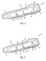
- the handle portion of the preferred embodiment of the present invention includes a skeletal support structure 12 having at least one window 14 therethrough and a cushion structure 16, at least part of which is disposed within the one window. While it is contemplated that the handle portion of the present invention may be incorporated into a multitude of devices that are intended to be grasped by a user's hand, for purposes of illustration, the instant handle portion will be shown in connection with hand tools, such as a circular saw, a hammer drill and a sander, as illustrated in FIGs. 12-14 , respectively.
- hand tools such as a circular saw, a hammer drill and a sander
- the support structure 12 is comprised of a relatively rigid material, such as nylon, rubber or urethane, and is configured to provide a volume around which the user's hand can grip with the user's thumb, palm and fingers in contact with cushion structure 16 surrounding the volume. By using a relatively rigid material, the support structure 12 imparts structural strength to the handle portion 10. While the support structure 12 assumes a predetermined configuration, the predetermined configuration may vary to suit individual applications. However, in general, the support structure 12 preferably includes a generally elliptical body 18 having a top surface 20, a bottom surface 21 and the at least one window 14. Alternatively, the body 18 may have a generally cylindrical shape, such as side handle 22 of the hammer drill illustrated in FIG. 13 . Often the support structure includes a plurality of windows having a predetermined size and configuration and that are separated by ribs 23 also having a predetermined size and configuration.
- a relatively rigid material such as nylon, rubber or urethane
- the windows 14 of the instant invention completely penetrate a depth of the body 18 so that the windows lack bottom surfaces, thus being open to a center of the handle portion 10.
- the support structure 12 acts as a skeletal scaffold for the handle portion 10.
- the predetermined size and configuration of the cushion structure 16 varies to suit individual applications.
- the cushion structure 16 is composed of an elastic substance, typically a thermal plastic elastomer such as Santoprene® or urethane, so that the cushion structure imparts flexibility and cushioning properties to the handle portion 10.
- the composite material of the cushion structure 16 may vary insofar as the composite material of the support structure 12 and the composite material of the cushion structure have adhesive properties that allow chemical bonding between the two structures.
- one ideal material is obtained via a process used by Trostel, Ltd., wherein urethane is injected into a mold, thereby forming a cushion layer having an outer surface layer that is typically smooth but may be textured, while inner layers form a microcellular material that foams underneath the outer surface.
- the foamed inner surface creates a soft cushion material that may be included in the cushion structure 16 of the various embodiments of the present invention.
- the thickness of the cushion structure 16 may vary, thereby imparting relatively more or less flexibility to the handle portion 10.
- the cushion structure 16 of the present tool handle portion 10 contemplates varying thicknesses to suit individual applications, but preferably includes a cushion structure 16 having a thickness from between 2 mm and 25 mm. Additionally, the cushion structure 16 may not have a uniform thickness throughout, but may include local maximum and minimum thickness values.
- the cushion structure 16 may be formed to have an arched cross section, which may result in a cushion structure that is thicker at predetermined radii when measured from a longitudinal axis of the tool handle portion 10.
- FIG. 11 illustrates an arched cushion structure 16 wherein a center region 16a is thicker than the remainder of the cushion structure.
- At least one orifice 17 having a generally hollow enlongated shaft 17a depending therefrom preferably extends through the cushion structure 16.
- the elongated shaft 17a is configured to align with a portion of the handle tool and to receive a threaded fastener 17b that maintains secure engagement of the tool handle portion with the hand tool with which the tool handle portion operates.
- the configuration of the cushion structure 16 may also vary, though it has a predetermined configuration that generally compliments the predetermined configuration of the support structure 12.
- the cushion structure 16 may be configured to promote flexibility and cushioning properties by changing the thickness of the cushion structure or increasing or decreasing the size of the support structure 12 underlying the cushion structure. This will increase or decrease the relative flexibility and cushioning properties of the handle portion 10.
- a manufacturer would first determine the locations on the handle portion 10 where flexibility is desired, and the degree of flexibility that is desired at those locations.
- the locations on the handle portion 10 wherein cushion and flexibility would be desired are those locations where the user's hand will contact the handle portion with his thumb, palm and fingers.
- the handle portion 10 is then manufactured accordingly using an injection molding process that is known in the art.
- the handle portion 10 is injected molded through a two-shot process, with the support structure 12 being formed with a first shot and the cushion structure 16 being formed with a second shot.
- the instant invention may preferably include multiple molds for creating separate halves of the handle portion 10 that will ultimately be assembled to one another to form a single handle portion.
- the support structure 12 is formed to have a corresponding predetermined configuration and a predetermined number of windows 14.
- a second mold is used to inject the cushion structure 16 over the support structure 12. In this manner, the cushion structure 16 is formed over an external surface of the support structure 12 and within the windows 14 of the support structure to be complimentary with the support structure.
- the cushion structure 16 may be confined to the windows 14 of the support structure 12 leaving the support structure exposed, or may overlay and obscure the support structure. Thus, when finished, the support structure 12 may not be visible underneath the cushion structure 16.
- varying the configuration of the support structure 12 will increase or decrease flexibility of the cushion structure.
- an inverse relationship emerges between the cushion structure 16 and the support structure 12. For example, if numerous windows 14 are provided in the support structure 12, the support structure will be more porous, dedicating more of the outer area of the volume of the support structure to the cushion structure 16 injected therein. If the windows 14 are few in number, there will be less surface area dedicated to the cushion structure 16.
- varying the size of the windows 14 will also vary the flexibility of the tool handle portion 10. The larger the window 14, the larger the cushion structure 16, which enhances flexibility. Generally, the greater the ratio of cushion structure 16 surface area to support structure 12 surface area, the more flexible the tool handle portion 10 will be once formed.
- Separating windows 14 by ribs 23 of varying thicknesses will additionally vary the flexibility of the tool handle portion 10. For example, if the ribs 23 separating the windows 14 are relatively narrow, flexibility will increase, whereas widening or increasing a cross sectional area of the ribs will commensurately decrease flexibility of the tool handle portion 10.
- FIGs. 2-9 represent a few of the myriad possibilities for configuring various examples of tool handles.
- the support structure 12 of the tool handle portion 10 includes the generally hollow, generally elliptical body 18, the top surface 20 and four longitudinal windows 14 that are separated at abutting ends 24 by relatively thin, transverse ribs 23 that are unitary with the body. The remaining circumferential borders of the windows 14 are surrounded by the body 18 of the support structure 12.
- FIG. 3 illustrates an example wherein the ribs 23 extend only partially into the windows 14 in a transverse direction.
- the cushion structure 16 of the instant example is continuous along at least a portion of the longitudinal length of the tool handle portion 10, and each rib 23 extends transversely into the windows 14 to oppose another rib at medial ends 26 of the ribs, separated by a relatively small portion of cushion structure. Because the ribs 23 do not separate the cushion structure 16 into discrete windows 14, the cushion structure in this example is continuous along a portion of the longitudinal length of the tool handle portion 10. Owing to the continuity of the cushion structure 16 as well as the relatively thin ribs 23, the tool handle portion 10 illustrate in FIG. 3 would be relatively more flexible than the embodiment illustrated in FIG. 2 .
- FIG. 4 shows yet another tool handle portion 10, wherein the flexibility and cushioning properties of the tool handle portion may be varied by varying the configuration of the cushion structure 16 and the support structure 12.
- the cushion structure 16 extends in a generally longitudinal direction along the tool handle portion 10, and because ribs 23 do not extend across the entire width of the cushion structure, the windows 14 are not separated by a discrete boundary. Instead, there exists only one window 14 that is punctuated along its longitudinal length by transverse ribs 23 that extend from the support structure 12 into the cushion structure 16 in a transverse direction, alternating the direction from which the ribs extend from the support structure into the cushion structure. Because the ribs 23 do not oppose one another, and because the ribs only extend across a portion of the cushion structure 16, the tool handle portion 10 illustrated in FIG. 4 would be relatively more flexible than either embodiment illustrated in FIGs. 2 and 3 .
- FIG. 5 illustrates yet another embodiment wherein the cushion structure 16 is divided into windows 16 separated by portions of the support structure 12 that include a longitudinal rib 28 that is intersected at 10 locations along a periphery of the cushion structure by transverse ribs 23.
- the longitudinal rib 28 generally bisects the cushion structure 16, while the transverse ribs 23 extend outward from the support structure 12, and are both connected to and unitary with the longitudinal rib.
- Each transverse rib 23 extends toward an opposing transverse rib.
- twelve windows 14 are created within the cushion structure 16, six on either side of the longitudinal rib 28, with opposing windows 14 on each side of the longitudinal rib being generally mirror images of one another.
- the longitudinal rib 28 as well as a plurality of transverse ribs 23, the embodiment illustrated in FIG. 5 would be relatively less flexible than the embodiments illustrated in FIGs. 2-4 .
- FIG. 6 Still another example is illustrated in FIG. 6 , wherein two longitudinal windows 14 are created by a longitudinal rib 28 that generally bisects the cushion structure 16. This example lacks transverse ribs 23. Accordingly, this example would be relatively flexible when compared to any of the previous embodiments illustrated in FIGs. 2-5 .
- FIG. 7 Another possible configuration for the tool handle portion 10 of the instant invention is illustrated in FIG. 7 , wherein the support structure 12 forms a lattice 30 across the cushion structure 16, resulting in a plurality of windows 14, for example 25, that are separated by diagonal ribs 32 crisscrossing the cushion structure. Because the support structure 12 intersects the cushion structure 16 so frequently, this embodiment would be relatively rigid when compared to any of the previous embodiments illustrated in FIGs. 2-6 .
- FIG. 8 illustrates yet another embodiment of the present tool handle portion 10.
- the windows 14 are generally circular, discrete units within the support structure 12, and are separated by portions of the support structure.
- the windows 14 are relatively numerous, but the support structure 12 separating each window is thicker than the ribs 23 previously illustrated.
- the embodiment illustrated in FIG. 8 would be relatively rigid.
- FIG. 9 illustrates a particularly simple example of the instant invention, wherein the cushion structure 16 includes a single window 14 that extends in a longitudinal direction within the support structure 12.
- FIG. 9 therefore represents a very flexible example of the instant invention, because it lacks any intrusion by the support structure 16 into the cushion structure 12.
- the instant invention is contemplated for use with a variety of tools, and as such, is uniquely adaptable to applications requiring differing degrees of flexibility.
- a hammer drill is used in applications such as drilling in concrete.
- the tool handle portion 10 of the hammer drill might preferably be configured to maximize the cushion and flexibility of the cushion structure 16 by decreasing the size of the support structure 12, increasing the size of the cushion structure, minimizing the number of windows 14, decreasing the depth of the cushion structure, or a combination of each.
- a tool such as a circular saw disperses the vibrational forces in a multi-directional manner, thereby minimizing the vertical vibration in the user's hand. Accordingly, minimal cushion and flexibility is needed in this application, which can be achieved by configuring the tool handle portion 10 to have smaller and more numerous windows 14, increases the overall size of the support structure 12, increase the number of ribs 23 intersecting the cushion structure 16, decreasing the overall size of the cushion structure, increasing the depth of the cushion structure, or a combination of each.
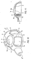
- FIGs. 15 and 16 illustrate yet another embodiment of the instant invention, wherein the cushion structure 16 is selectively removable from the support structure 12, which is affixed to the hand tool via a threaded fastener 34 or adhesive, for example.
- the support structure 12 includes at least one window located adjacent to a predetermined portion around which the user's hand can grip.
- the cushion structure 16 is not bonded therein, but is instead configured to selectively engage or disengage the support structure 12.
- the cushion structure 16 may include a second support structure 36 that is disposed on or within the cushion structure. While it is contemplated that the second support structure 36 may assume a variety of configurations to suit individual applications, FIG. 15 illustrates the second support structure to be an annular ring disposed around a lower circumference of the cushion structure 16. While serving to provide additional support to the cushion structure 16, the second support structure 36 may also be configured to matingly engage the support structure 12, thereby mechanically attaching the cushion structure 16 to the support structure.
- the second support structure 36 may include an annular recess 38 along an internal circumference thereof, while the support structure 12 includes an annular flange 40 disposed around a lower circumference of the support structure.
- the annular recess 38 of the second support structure 36 matingly engages the annular flange 40 of the support structure to lockingly engage the cushion structure to the support structure.
- the cushion structure 12 may optionally be configured to envelop the second support structure 36.
- the cushion structure 16 itself may be configured to engage the support structure 12.
- the removable cushion structure 16 would prevent the second support structure from directly contacting the support structure 12, which further insulates the tool handle 10 from vibrational forces.
- FIG. 15 illustrates a second support structure 16
- the instant embodiment contemplates a selectively removable cushion structure that lacks the second support structure 36 altogether.
- the cushion structure 16 itself may include an annular recess (not shown) to engage the annular flange 40 of the support structure 12.
- the cushion structure 16 may be sized and configured to engage the support structure 12 in a snap-fit engagement, a frictional engagement, or other engagement.
- the cushion structure may include at least one locator pin 42 while the support structure may include a corresponding locator recess 44 that is sized and configured to receive the at least one locator pin.
- the support structure 12 and cushion structure 16 may optionally include a plurality of locator recesses 44 and locator pins 42, respectively.
- the predetermined configuration of the locator pins 42 and locator recesses 44 further promotes predetermined alignment of the cushion structure 16 with the support structure 12 as the two structures matingly engage one another.
- said step of forming a support structure comprises forming a plurality of windows in the support structure to increase flexibility.
- said step of forming a plurality of windows comprises forming fewer windows to decrease flexibility .
- said step of forming a support structure comprises forming the at least one window to be either larger to impart greater flexibility or smaller to impart less flexibility.
- said step of forming a support structure comprises including a predetermined number of ribs to separate the multiple windows from one another.
- said ribs are formed to be relatively thick to impart less flexibility or relatively thin to impart greater flexibility.
- said step of forming the cushion structure includes determining a thickness of the cushion structure commensurate with the desired degree of flexibility.
- said step of determining the thickness of the cushion structure includes forming a relatively thicker cushion structure for less flexibility or forming a relatively thinner cushion structure for greater flexibility.
- said step of determining the thickness of the cushion structure includes forming local areas of the cushion structure that are thicker than other areas of the cushion structure.
- Another embodiment of the invention provides a handle portion of a hand tool housing of the type that is ergonomically configured for normal gripping by a user's hand and wherein the pressure points of contact by at least one predetermined portion of the hand principally contact a relatively soft tactile cushion surface, comprising:
- a second support structure is disposed within said cushion structure.
- said second support structure is configured to matingly engage said at least one support structure.
- said second support structure is configured to lockingly engage said at least one support structure in a snap-fit engagement.
- said second support structure comprises an annular structure disposed around a lower circumference of said cushion structure.
- said at least one support structure includes an annular flange.
- said cushion structure includes a recess correspondingly sized and configured to lockingly engage said annular flange.
- said at least one support structure further comprises at least one locator recess.
- said cushion structure includes at least one locator pin configured to matingly engage said at least one locator recess.
- said at least one support structure further comprises at least one fastener to affix said at least one support structure to the hand tool.
Landscapes
- Engineering & Computer Science (AREA)
- Mechanical Engineering (AREA)
- Purses, Travelling Bags, Baskets, Or Suitcases (AREA)
- Professional, Industrial, Or Sporting Protective Garments (AREA)
Claims (10)
- Kissengriff (10) von dem zum Greifen für eine menschliche Hand ausgelegten Typ, umfassend:eine äußere skelettartige Stützstruktur (12), welche einen Innenhohlraum-Aufbau hat, wobei die skelettartige Stützstruktur (12) eine durch eine Vielzahl von Rippen (23) getrennte Vielzahl von Fenstern (14) umfasst, wobei die Vielzahl von Rippen (23) eine im Wesentlichen den Innenhohlraum definierende Innenoberfläche und eine im Wesentlichen damit flächengleiche und das Äußere der skelettartigen Stützstruktur (12) definierende Außenoberfläche haben; undeine innerhalb eines jeden der Vielzahl von Fenstern (14) spritzgegossene Polsterung (16);
dadurch gekennzeichnet, dassjede der Vielzahl von Rippen (23) eine Breite hat, die kleiner ist als ein Durchmesser des größten Kreises, der innerhalb eines der Vielzahl von Fenstern (14) passen würde. - Kissengriff (10) nach Anspruch 1, zusätzlich umfassend zwei Stützstrukturen (12), die auf eine komplementäre Weise zusammenpassen um einen einzelnen Kissengriff (10) zu bilden.
- Kissengriff (10) nach Anspruch 1, wobei die Stützstruktur (12) ein Material umfasst, das an der Polsterung (16) binden wird.
- Kissengriff (10) nach Anspruch 1, wobei die Stützstruktur (12) Nylon umfasst.
- Kissengriff (10) nach Anspruch 4, wobei die Polsterung (16) einen thermisch formbaren Elastoplast umfasst.
- Kissengriff (10) nach Anspruch 1, wobei die Stützstruktur (12) Urethan umfasst.
- Kissengriff (10) nach Anspruch 6, wobei die Polsterung (16) Urethan umfasst.
- Kissengriff (10) nach Anspruch 1, wobei die Polsterung (16) eine uneinheitliche Dicke hat.
- Kissengriff (10) nach Anspruch 1, wobei jedes der Vielzahl von Fenstern (14) die Stützstruktur (12) vollständig durchdringt.
- Verfahren zum Herstellen eines polsternde Eigenschaften habenden Kissengriffs (10) ausgelegt zum Greifen für eine menschliche Hand, umfassend:Auswählen eines ersten Verbundmaterials;Formen einer äußeren skelettartigen Stützstruktur (12), welche einen Innenhohlraum-Aufbau hat, aus dem ersten Verbundmaterial, wobei der Innenhohlraum-Aufbau eine Vielzahl von offenen Fenstern (14), die nicht das erste Verbundmaterial enthalten, hat, wobei die Vielzahl von Fenstern (14) durch eine Vielzahl von Rippen (23) getrennt sind, wobei die Vielzahl von Rippen (23) eine den Innenhohlraum im Wesentlichen definierende Innenoberfläche und eine im Wesentlichen flächengleich mit und das Äußere der skelettartigen Stützstruktur (12) definierende Außenoberfläche haben;Auswählen eines zum Anhaften an das erste Material geeigneten zweiten Verbundmaterials; undSpritzgießen einer aus dem zweiten Verbundmaterial gemachten Polsterung (16) hauptsächlich innerhalb der Fenster (14) der Stützstruktur (12), um eine Polsterung (16), die zumindest an die Außenoberfläche der Stützstruktur (12) gebunden ist, zu formen;
dadurch gekennzeichnet, dassdie äußere skelettartige Stützstruktur (12) so geformt wird, dass jede der Vielzahl von Rippen (23) eine Breite hat, die kleiner ist als ein Durchmesser des größten Kreises, der innerhalb eines der Vielzahl von Fenstern (14) passen würde.
Applications Claiming Priority (2)
| Application Number | Priority Date | Filing Date | Title |
|---|---|---|---|
| US10/440,857 US7770262B2 (en) | 2003-05-19 | 2003-05-19 | Cushion grip handle |
| US440857 | 2003-05-19 |
Publications (3)
| Publication Number | Publication Date |
|---|---|
| EP1479486A2 EP1479486A2 (de) | 2004-11-24 |
| EP1479486A3 EP1479486A3 (de) | 2005-11-23 |
| EP1479486B1 true EP1479486B1 (de) | 2010-01-13 |
Family
ID=33097949
Family Applications (1)
| Application Number | Title | Priority Date | Filing Date |
|---|---|---|---|
| EP04011795A Expired - Lifetime EP1479486B1 (de) | 2003-05-19 | 2004-05-18 | Kissengriff |
Country Status (3)
| Country | Link |
|---|---|
| US (1) | US7770262B2 (de) |
| EP (1) | EP1479486B1 (de) |
| DE (1) | DE602004025063D1 (de) |
Families Citing this family (24)
| Publication number | Priority date | Publication date | Assignee | Title |
|---|---|---|---|---|
| US7117560B2 (en) * | 2004-07-28 | 2006-10-10 | Hsiu-Man Yu Chen | Handle of an adhesive-tape cutter able to accommodate articles |
| DE102004057613A1 (de) * | 2004-11-29 | 2006-06-08 | Hilti Ag | Griffanordnung einer Handkreissäge |
| US20100312129A1 (en) | 2005-01-26 | 2010-12-09 | Schecter Stuart O | Cardiovascular haptic handle system |
| US7654183B2 (en) * | 2006-01-23 | 2010-02-02 | Worktools, Inc. | Compact heavy duty hole punch |
| USD589322S1 (en) | 2006-10-05 | 2009-03-31 | Lowe's Companies, Inc. | Tool handle |
| DE102007009169A1 (de) * | 2007-02-26 | 2008-08-28 | Robert Bosch Gmbh | Handgriff |
| FR2936728B1 (fr) * | 2008-10-08 | 2010-12-10 | Nespoli Engineering Kereskedelmi Korlatolt Fedelossegu Tarsagag Kft | Manche pour outil manuel et outil ainsi equipe |
| JP5352412B2 (ja) | 2009-10-14 | 2013-11-27 | 株式会社マキタ | 電動工具 |
| CN201525003U (zh) * | 2009-11-02 | 2010-07-14 | 南京德朔实业有限公司 | 一种电动榔头 |
| US8942828B1 (en) | 2011-04-13 | 2015-01-27 | Stuart Schecter, LLC | Minimally invasive cardiovascular support system with true haptic coupling |
| US9073200B2 (en) | 2012-02-29 | 2015-07-07 | Tech Stape and Nail, Inc. | Pliant removeable airbrush grip |
| US10013082B2 (en) | 2012-06-05 | 2018-07-03 | Stuart Schecter, LLC | Operating system with haptic interface for minimally invasive, hand-held surgical instrument |
| US9162354B1 (en) * | 2014-03-26 | 2015-10-20 | Green Guard Industry Ltd. | Handle cover structure |
| BR112017005458A2 (pt) * | 2014-09-22 | 2017-12-05 | Victor Equipment Co | cabo ergonômico do maçarico de soldadura com empunhaduras intercambiáveis |
| USD767718S1 (en) | 2015-06-17 | 2016-09-27 | George Robert Lampman | Airbrush grip |
| USD848238S1 (en) * | 2016-02-02 | 2019-05-14 | Kraft Tool Company | Handle |
| USD853821S1 (en) * | 2016-07-15 | 2019-07-16 | Kraft Tool Company | Handle |
| USD854395S1 (en) | 2018-01-30 | 2019-07-23 | Kraft Tool Company | Handle |
| USD873644S1 (en) | 2018-02-01 | 2020-01-28 | Kraft Tool Company | Handle |
| USD874242S1 (en) | 2018-02-01 | 2020-02-04 | Kraft Tool Company | Handle |
| USD965230S1 (en) | 2020-11-10 | 2022-09-27 | Billy A. Anderson | Sleeve for a handle |
| CN219311210U (zh) | 2021-05-14 | 2023-07-07 | 创科无线普通合伙 | 一种用于动力工具的手柄 |
| US11851895B2 (en) | 2021-09-28 | 2023-12-26 | Acufloor, LLC | Grout float and handle for use with same |
| USD985355S1 (en) | 2022-09-28 | 2023-05-09 | Acufloor, LLC | Grout float and grout float handle |
Family Cites Families (52)
| Publication number | Priority date | Publication date | Assignee | Title |
|---|---|---|---|---|
| US604706A (en) * | 1898-05-24 | Hand-grip | ||
| US3185001A (en) * | 1963-11-12 | 1965-05-25 | Rodney A Viator | Wrench-tool handle grip |
| US3189069A (en) * | 1963-12-06 | 1965-06-15 | Stanley Works | Tool handle with resilient gripping means |
| US3340914A (en) * | 1965-05-10 | 1967-09-12 | James B Ricks | Ratchet grip |
| US3565351A (en) * | 1968-11-14 | 1971-02-23 | Thorvald S Ross Jr | Impactor |
| GB1596086A (en) | 1978-05-19 | 1981-08-19 | Bowmer G M | Handles |
| US4347648A (en) * | 1980-05-12 | 1982-09-07 | Dennison Manufacturing Company | Ladder strap harnessing device with webbed tail |
| US4331193A (en) * | 1980-06-09 | 1982-05-25 | White Development Corporation | Flexible handle for percussive tool employing improved shaft member |
| GB2147242B (en) * | 1981-08-22 | 1985-12-04 | Wilkinson Sword Ltd | A handle, in particular for a hand tool |
| DE3525163A1 (de) * | 1985-07-13 | 1987-01-22 | Werner Hermann Wera Werke | Werkzeugheft, insbesondere fuer schraubendreher |
| JPS62156482U (de) * | 1986-03-25 | 1987-10-05 | ||
| US4768406A (en) * | 1986-04-22 | 1988-09-06 | Edwin Fitzwater | Torque compensating apparatus |
| US4721021A (en) * | 1986-09-10 | 1988-01-26 | Kusznir Phillip S | Handle structure |
| US4837892A (en) * | 1988-03-04 | 1989-06-13 | Conair Corporation | Cushioned handle structure for personal care appliances |
| US5099724A (en) * | 1988-04-11 | 1992-03-31 | Reddy Jr William L | Striking device |
| US4969231A (en) * | 1989-05-17 | 1990-11-13 | Easco Hand Tools, Inc. | Hand tool handle having end cap with indicia |
| US5211085A (en) * | 1992-03-31 | 1993-05-18 | Liou Mou T | Hammer |
| US5339482A (en) * | 1992-07-21 | 1994-08-23 | Johnson & Johnson Consumer Products, Inc. | Toothbrush having non-slip surface |
| US5280739A (en) * | 1992-12-03 | 1994-01-25 | Liou Mou T | Handle of a hammer having a shock absorbing configuration |
| FR2714863B1 (fr) * | 1994-01-11 | 1996-03-29 | Facom | Manche d'outil. |
| US5530989A (en) * | 1994-12-20 | 1996-07-02 | The Dow Chemical Company | Dual durometer handles |
| DE19513245A1 (de) * | 1995-04-07 | 1996-10-10 | Leifheit Ag | Handgriff für Küchenarbeitsgerät |
| US5581845A (en) * | 1995-05-22 | 1996-12-10 | Yang; Syh-Yn | Handle for garden tool |
| CA2182235C (en) * | 1995-08-10 | 2006-02-28 | William W. Barton | Brush with improved grip construction and method of manufacture thereof |
| US5781956A (en) * | 1996-01-17 | 1998-07-21 | Marshalltown Trowel Company | Plastic molded float handle |
| US5781958A (en) * | 1996-02-14 | 1998-07-21 | Gillette Canada Inc. | Brush handle |
| US5752287A (en) * | 1996-10-01 | 1998-05-19 | Wheat; Richard Thomas | Screw paint brush |
| US5862571A (en) * | 1997-01-10 | 1999-01-26 | Hp Intellectual Corp. | Comfort grip handle and process |
| US5911798A (en) * | 1997-04-09 | 1999-06-15 | Hand Tool Design Corporation | Handle extension for ratchet wrench |
| US6101895A (en) * | 1997-07-25 | 2000-08-15 | Shimano, Inc. | Grip for a bicycle shift control device |
| DE29803967U1 (de) * | 1998-03-07 | 1998-04-23 | Felo-Werkzeugfabrik Holland-Letz GmbH, 35279 Neustadt | Werkzeug-Griff, insbesondere für Elektronik-Schraubendreher und ähnliche Geräte |
| US6202511B1 (en) | 1998-08-14 | 2001-03-20 | The Stanley Works | Vibration damped hammer |
| US6199460B1 (en) * | 1999-04-02 | 2001-03-13 | Chi Yu Lo | Tool handle |
| US6220128B1 (en) * | 1999-05-04 | 2001-04-24 | Bobby Hu | Shock absorbing handle of hand impact tool |
| US6308378B1 (en) * | 1999-06-01 | 2001-10-30 | Porter-Cable Corporation | Frictional gripping arrangement for a power tool handle |
| US6161256A (en) * | 1999-11-03 | 2000-12-19 | Quiring; Herbert J. | Drill handle cover |
| US6223627B1 (en) * | 1999-12-14 | 2001-05-01 | Yi Jing Jan | Anti-shock structure of a hammer handle |
| WO2001053046A1 (de) * | 2000-01-19 | 2001-07-26 | Adolf Würth GmbH & Co. KG | Griff für ein werkzeug |
| US6349451B1 (en) * | 2000-01-28 | 2002-02-26 | Robert D. Newman/Specialty Products Of Greenwood, Missouri, Inc. | Universal tool handle configured for various extension pole connectors |
| US6305815B1 (en) * | 2000-02-22 | 2001-10-23 | Home Soon Enterprise Co., Ltd. | Screwdriver having a bit set slidably received in a handle of the screwdriver |
| US6230366B1 (en) * | 2000-05-02 | 2001-05-15 | Chang-Ming Lin | Multicolored handle |
| US6408524B1 (en) * | 2000-06-16 | 2002-06-25 | Yin-Chu Lai | Tableware grip structure with comfortable touch feeling |
| US6604256B1 (en) * | 2000-08-01 | 2003-08-12 | Walter W. Pytlewski | Grout float assembly |
| US6662406B2 (en) * | 2000-08-11 | 2003-12-16 | Wki Holding Company, Inc. | Garden tools and ergonomic handles therefor |
| US6742215B2 (en) * | 2001-02-06 | 2004-06-01 | A. Richard S.E.N.C. | Ergonomic drywall knife |
| US6405619B1 (en) * | 2001-03-23 | 2002-06-18 | Wki Holding Company, Inc. | Self-securing tool handle |
| US6513198B2 (en) * | 2001-06-26 | 2003-02-04 | Hanlong Industrial Co., Ltd. | Plastic handle structure of a clamp tool |
| US6721997B2 (en) * | 2002-06-05 | 2004-04-20 | Prudential Co., Ltd. | Handle for tape dispenser |
| US20030233734A1 (en) * | 2002-06-20 | 2003-12-25 | Mcguyer Carter W. | Utensil, kit and method |
| TW556636U (en) * | 2002-08-09 | 2003-10-01 | Chen Chang Rong | Improved shock-proof structure for hammer |
| US6776073B1 (en) * | 2003-01-03 | 2004-08-17 | Role Associates, Llc | Hand pliers |
| US6772994B1 (en) * | 2003-04-22 | 2004-08-10 | Mayhew Tool Products | Pry bar handle |
-
2003
- 2003-05-19 US US10/440,857 patent/US7770262B2/en not_active Expired - Fee Related
-
2004
- 2004-05-18 EP EP04011795A patent/EP1479486B1/de not_active Expired - Lifetime
- 2004-05-18 DE DE602004025063T patent/DE602004025063D1/de not_active Expired - Lifetime
Also Published As
| Publication number | Publication date |
|---|---|
| DE602004025063D1 (de) | 2010-03-04 |
| US7770262B2 (en) | 2010-08-10 |
| EP1479486A3 (de) | 2005-11-23 |
| EP1479486A2 (de) | 2004-11-24 |
| US20040231100A1 (en) | 2004-11-25 |
Similar Documents
| Publication | Publication Date | Title |
|---|---|---|
| EP1479486B1 (de) | Kissengriff | |
| CA2423996C (en) | Grip element and method of manufacture thereof | |
| EP0353919B1 (de) | Handgriff für Nassrasierer | |
| US5964009A (en) | Tool with dual-material handle | |
| US7676890B2 (en) | Vibration dampening handle for a powered apparatus | |
| US4721021A (en) | Handle structure | |
| US7877843B2 (en) | Handle | |
| CN101384413B (zh) | 用于制造手柄的方法 | |
| US20080163463A1 (en) | Tool handle | |
| US20120222525A1 (en) | Tool handle and method for manufacturing the same | |
| US6108870A (en) | Tool handle combination | |
| US20030172498A1 (en) | Apparatus to cushion and dampen vibration and method | |
| US8555512B2 (en) | Handle of tool | |
| US6485211B1 (en) | Easily assembled grip element | |
| EP1602453A2 (de) | Griffanordnung für Werkzeug | |
| US5581845A (en) | Handle for garden tool | |
| US20060083575A1 (en) | Device for right grip of writing tools | |
| EP1415769A1 (de) | Griffanordnung für Handwerkzeuge | |
| CN1626302A (zh) | 一种锯手柄抓持部 | |
| CN1986168B (zh) | 手持式工具机 | |
| KR200189562Y1 (ko) | 자동차용 핸들커버 | |
| US20190126523A1 (en) | Multifunctional viscoelastic compressive applicator | |
| US20200016778A1 (en) | Cutting Tool With Soft Handles and Method of Making Same | |
| EP1832396A1 (de) | Griffanordnung für Werkzeug | |
| NZ545256A (en) | Orbital sander with vertical handle |
Legal Events
| Date | Code | Title | Description |
|---|---|---|---|
| PUAI | Public reference made under article 153(3) epc to a published international application that has entered the european phase |
Free format text: ORIGINAL CODE: 0009012 |
|
| AK | Designated contracting states |
Kind code of ref document: A2 Designated state(s): AT BE BG CH CY CZ DE DK EE ES FI FR GB GR HU IE IT LI LU MC NL PL PT RO SE SI SK TR |
|
| AX | Request for extension of the european patent |
Extension state: AL HR LT LV MK |
|
| PUAL | Search report despatched |
Free format text: ORIGINAL CODE: 0009013 |
|
| AK | Designated contracting states |
Kind code of ref document: A3 Designated state(s): AT BE BG CH CY CZ DE DK EE ES FI FR GB GR HU IE IT LI LU MC NL PL PT RO SE SI SK TR |
|
| AX | Request for extension of the european patent |
Extension state: AL HR LT LV MK |
|
| RIC1 | Information provided on ipc code assigned before grant |
Ipc: 7B 25F 5/00 A Ipc: 7B 25G 1/01 B |
|
| 17P | Request for examination filed |
Effective date: 20060516 |
|
| AKX | Designation fees paid |
Designated state(s): DE FR GB IT |
|
| 17Q | First examination report despatched |
Effective date: 20070524 |
|
| GRAP | Despatch of communication of intention to grant a patent |
Free format text: ORIGINAL CODE: EPIDOSNIGR1 |
|
| GRAS | Grant fee paid |
Free format text: ORIGINAL CODE: EPIDOSNIGR3 |
|
| GRAA | (expected) grant |
Free format text: ORIGINAL CODE: 0009210 |
|
| AK | Designated contracting states |
Kind code of ref document: B1 Designated state(s): DE FR GB IT |
|
| REG | Reference to a national code |
Ref country code: GB Ref legal event code: FG4D |
|
| REF | Corresponds to: |
Ref document number: 602004025063 Country of ref document: DE Date of ref document: 20100304 Kind code of ref document: P |
|
| PLBE | No opposition filed within time limit |
Free format text: ORIGINAL CODE: 0009261 |
|
| STAA | Information on the status of an ep patent application or granted ep patent |
Free format text: STATUS: NO OPPOSITION FILED WITHIN TIME LIMIT |
|
| 26N | No opposition filed |
Effective date: 20101014 |
|
| PG25 | Lapsed in a contracting state [announced via postgrant information from national office to epo] |
Ref country code: IT Free format text: LAPSE BECAUSE OF FAILURE TO SUBMIT A TRANSLATION OF THE DESCRIPTION OR TO PAY THE FEE WITHIN THE PRESCRIBED TIME-LIMIT Effective date: 20100113 |
|
| REG | Reference to a national code |
Ref country code: FR Ref legal event code: PLFP Year of fee payment: 13 |
|
| REG | Reference to a national code |
Ref country code: FR Ref legal event code: PLFP Year of fee payment: 14 |
|
| REG | Reference to a national code |
Ref country code: FR Ref legal event code: PLFP Year of fee payment: 15 |
|
| PGFP | Annual fee paid to national office [announced via postgrant information from national office to epo] |
Ref country code: DE Payment date: 20190716 Year of fee payment: 16 |
|
| PGFP | Annual fee paid to national office [announced via postgrant information from national office to epo] |
Ref country code: FR Payment date: 20200519 Year of fee payment: 17 |
|
| PGFP | Annual fee paid to national office [announced via postgrant information from national office to epo] |
Ref country code: GB Payment date: 20200522 Year of fee payment: 17 |
|
| REG | Reference to a national code |
Ref country code: DE Ref legal event code: R119 Ref document number: 602004025063 Country of ref document: DE |
|
| PG25 | Lapsed in a contracting state [announced via postgrant information from national office to epo] |
Ref country code: DE Free format text: LAPSE BECAUSE OF NON-PAYMENT OF DUE FEES Effective date: 20201201 |
|
| GBPC | Gb: european patent ceased through non-payment of renewal fee |
Effective date: 20210518 |
|
| PG25 | Lapsed in a contracting state [announced via postgrant information from national office to epo] |
Ref country code: GB Free format text: LAPSE BECAUSE OF NON-PAYMENT OF DUE FEES Effective date: 20210518 |
|
| PG25 | Lapsed in a contracting state [announced via postgrant information from national office to epo] |
Ref country code: FR Free format text: LAPSE BECAUSE OF NON-PAYMENT OF DUE FEES Effective date: 20210531 |