EP1479587A2 - Circuit pour ajuster des sensors inductifs - Google Patents
Circuit pour ajuster des sensors inductifs Download PDFInfo
- Publication number
- EP1479587A2 EP1479587A2 EP04450066A EP04450066A EP1479587A2 EP 1479587 A2 EP1479587 A2 EP 1479587A2 EP 04450066 A EP04450066 A EP 04450066A EP 04450066 A EP04450066 A EP 04450066A EP 1479587 A2 EP1479587 A2 EP 1479587A2
- Authority
- EP
- European Patent Office
- Prior art keywords
- microcontroller
- sensor
- circuit arrangement
- adjustment
- rail
- Prior art date
- Legal status (The legal status is an assumption and is not a legal conclusion. Google has not performed a legal analysis and makes no representation as to the accuracy of the status listed.)
- Granted
Links
- 230000001939 inductive effect Effects 0.000 title claims abstract description 7
- 239000003990 capacitor Substances 0.000 claims abstract description 10
- 230000000903 blocking effect Effects 0.000 claims description 3
- 230000004913 activation Effects 0.000 claims 3
- 238000000034 method Methods 0.000 description 22
- 230000008569 process Effects 0.000 description 9
- XEEYBQQBJWHFJM-UHFFFAOYSA-N Iron Chemical group [Fe] XEEYBQQBJWHFJM-UHFFFAOYSA-N 0.000 description 5
- 230000008901 benefit Effects 0.000 description 5
- 238000013016 damping Methods 0.000 description 5
- 238000011156 evaluation Methods 0.000 description 5
- 230000008859 change Effects 0.000 description 4
- 230000005540 biological transmission Effects 0.000 description 3
- 230000006870 function Effects 0.000 description 3
- 230000002411 adverse Effects 0.000 description 2
- 230000002238 attenuated effect Effects 0.000 description 2
- 230000006399 behavior Effects 0.000 description 2
- 238000009434 installation Methods 0.000 description 2
- 229910052742 iron Inorganic materials 0.000 description 2
- 230000035945 sensitivity Effects 0.000 description 2
- 238000012549 training Methods 0.000 description 2
- 206010010219 Compulsions Diseases 0.000 description 1
- 238000013459 approach Methods 0.000 description 1
- 230000000712 assembly Effects 0.000 description 1
- 238000000429 assembly Methods 0.000 description 1
- 230000009286 beneficial effect Effects 0.000 description 1
- 238000012937 correction Methods 0.000 description 1
- 230000007423 decrease Effects 0.000 description 1
- 238000013461 design Methods 0.000 description 1
- 238000001514 detection method Methods 0.000 description 1
- 238000011161 development Methods 0.000 description 1
- 230000018109 developmental process Effects 0.000 description 1
- 238000010586 diagram Methods 0.000 description 1
- 230000000694 effects Effects 0.000 description 1
- 238000005516 engineering process Methods 0.000 description 1
- 230000001747 exhibiting effect Effects 0.000 description 1
- 231100001261 hazardous Toxicity 0.000 description 1
- 230000006266 hibernation Effects 0.000 description 1
- 235000000396 iron Nutrition 0.000 description 1
- 238000005259 measurement Methods 0.000 description 1
- 238000012986 modification Methods 0.000 description 1
- 230000004048 modification Effects 0.000 description 1
- 230000010355 oscillation Effects 0.000 description 1
- 238000012545 processing Methods 0.000 description 1
- 230000009467 reduction Effects 0.000 description 1
- 238000005096 rolling process Methods 0.000 description 1
- 230000008054 signal transmission Effects 0.000 description 1
- 230000011664 signaling Effects 0.000 description 1
- 230000009131 signaling function Effects 0.000 description 1
- 239000000126 substance Substances 0.000 description 1
- 238000012546 transfer Methods 0.000 description 1
- 230000001960 triggered effect Effects 0.000 description 1
Images


Classifications
-
- B—PERFORMING OPERATIONS; TRANSPORTING
- B61—RAILWAYS
- B61L—GUIDING RAILWAY TRAFFIC; ENSURING THE SAFETY OF RAILWAY TRAFFIC
- B61L1/00—Devices along the route controlled by interaction with the vehicle or train
- B61L1/02—Electric devices associated with track, e.g. rail contacts
- B61L1/08—Electric devices associated with track, e.g. rail contacts magnetically actuated; electrostatically actuated
-
- B—PERFORMING OPERATIONS; TRANSPORTING
- B61—RAILWAYS
- B61L—GUIDING RAILWAY TRAFFIC; ENSURING THE SAFETY OF RAILWAY TRAFFIC
- B61L1/00—Devices along the route controlled by interaction with the vehicle or train
- B61L1/16—Devices for counting axles; Devices for counting vehicles
- B61L1/167—Circuit details
-
- G—PHYSICS
- G01—MEASURING; TESTING
- G01D—MEASURING NOT SPECIALLY ADAPTED FOR A SPECIFIC VARIABLE; ARRANGEMENTS FOR MEASURING TWO OR MORE VARIABLES NOT COVERED IN A SINGLE OTHER SUBCLASS; TARIFF METERING APPARATUS; MEASURING OR TESTING NOT OTHERWISE PROVIDED FOR
- G01D3/00—Indicating or recording apparatus with provision for the special purposes referred to in the subgroups
- G01D3/02—Indicating or recording apparatus with provision for the special purposes referred to in the subgroups with provision for altering or correcting the law of variation
- G01D3/022—Indicating or recording apparatus with provision for the special purposes referred to in the subgroups with provision for altering or correcting the law of variation having an ideal characteristic, map or correction data stored in a digital memory
Definitions
- the invention relates to a circuit arrangement for matching of inductive sensors, in particular provided in the track area of tracks Two-wire wheel sensors in the mounting position on the rail different influences, for example due to the rail shape, the Mounting position or the current temperature subject.
- Devices for detecting railway wheels are increasingly with Help realized by inductive sensors.
- Most are two independent sensors in a common housing in the rail longitudinal direction one behind the other arranged. Your job is to provide signals with high availability place, which is usually passed over a cable route in an indoor unit and there be valued accordingly.
- Signaling functions such as For example, the presence of a rail vehicle, the direction of travel detection or a track vacancy message in the form of an axis count be built.
- DE19915597A1 and DE 3234651 A1 are concerned with such wheel sensors.
- each sensor system from a sensor coil with or without iron core, and an oscillator circuit.
- the sensor coil forms a resonant circuit with a capacitor, which is an alternating magnetic field builds in its environment. Once a wheel flange of a wheel in the effective range the sensor coil penetrates, the resonant circuit is attenuated, because it is the Irons of the flange wring energy through eddy current losses. Subsequently changes the voltage amplitude or frequency of the resonant circuit, which in Most sensor circuits in a change in the power consumption of the sensor system is converted.
- This current signal is preferably in a Conducted two-wire line in the interior of a security system and there for example, converted by means of comparator circuits to switching signals and then further processing for different tasks in the frame supplied to the security system.
- the DIN19234 describes such a current interface of sensors, such as they are also applied in the practice of wheel sensor technology.
- There is a quiescent current level set by about 3 mA the damping of the sensor, in the standard sheet referred to as electrical transducer, drops to about 1 mA.
- State of Technique are other current levels, for example, 5, 8, or 20 mA in Hibernation.
- the mounting position of the wheel sensor is determined by the geometry of the rail - Wheel intended in narrow limits.
- the acquisition of the Wheel flange of the wheels, because thereby the wheel sensor to about 40-50 mm below Rail upper edge arranged at a very sheltered place in the track area can be.
- the iron of the rail head acts dampening on the wheel sensor.
- This influence must be in the sensor circuit are taken into account, for example, in the form of a pre-adjustment of the sensitivity of the sensor system.
- the sensor system is only then sufficient sensitive and fit for his job when it comes to rail is in the correct position and the rail head as partially damped Element acts.
- the object of the invention is to provide a circuit arrangement of mentioned type by which the disadvantages are eliminated and a perfect quick and durable adjustment of the sensors allows becomes.
- a sub-task of the invention is also due to temperature changes to eliminate disadvantages due to the adjustment time.
- the circuit arrangement passive balancing elements in particular in the form of resistors or capacitors and at least one microcontroller having a Control command can be activated so that he controlled by him switch the balancing elements in preselectable order to the oscillator coil on or from this shuts off until, for example, by a predetermined amount for the nominal quiescent current the sensor defined balance is reached, preferably for Example in the microcontroller a non-volatile memory is provided, which is the Switch positions in the adjustment state when deactivated after adjustment Microcontroller holds.
- the values of the passive components are preferably in binary Ordered by the adjustment range in fine levels with a minimum number to cover the components.
- the microcontroller compares according to the program the current absorbed by the circuit or the oscillation frequency or both with internal reference values and finally stop the adjustment process, as soon as the result matches the reference best. Since the State of the outputs stored according to the invention in a non-volatile memory In the event of a power failure, the calibration state can not be lost.
- This invention is based on the fact that the properties of a Coil by switching on and off certain passive components between Coil outputs can be changed. For example, the coil quality reduced when an ohmic resistance is switched on. The natural frequency The coil is reduced when a capacity is switched on.
- An important advantage of the device according to the invention is the Adjustment of the sensor system after installation on the track at least not in Hazardous area, ie at a sufficient distance from the track area, preferably in the interior of the signal system, for example in the field of signal evaluation devices, to carry out.
- the microcontroller is connected to the lines of the wheel sensor, by a transmitted over this line, from the supply voltage the sensor different signal activatable and shows the done Adjustment by an acknowledgment signal.
- the acknowledgment message can be sent back to the point via the cable route from which the adjustment command was sent. This additional Possibility completely excludes any operating errors and increases the Availability of the plant.
- the command is to perform the adjustment fed to the sensor circuit via the sensor connection cable.
- a voltage pulse is applied to the wires whose Value is significantly higher than that of the supply voltage.
- This impulse is in the sensor input circuit prepared and the microcontroller as an input command fed.
- the pulse should be significantly longer than e.g. the typical length of an interference pulse.
- the evaluation of the transmitted pulse in the microcontroller can be done according to the program so that glitches readily can be distinguished from Nutzimpulsen.
- Another possibility is to activate a defined one Frequency exhibiting pulse used.
- the invention offers the possibility in a further embodiment on, the command transmission by means of the input of the microcontroller detectable serial data words.
- This technique allows the transmission various commands. This opens up further advantages of the invention, For example, the adjustment of the sensor to a certain value, the over a serial interface is specified.
- a balancing device In order to initiate the adjustment, a balancing device is required. This can be in a simplest form, a voltage source, the at a Place the cable route, for example, at a terminal point, the wires of Radsensor ein is switched on. In a preferred embodiment are in the tuning transmitter a timer for the length of the transmit pulse and a receive circuit integrated for the representation of an acknowledgment signal.
- An adjustment device with facilities for sending and receiving Serial data is switched to the wires of the wheel sensor cable.
- the balancing device is already integrated into the sensor evaluation module. This Embodiment is particularly comfortable, because the handling with a separate Device omitted. It is crucial that the command to trigger the adjustment preferably triggered manually, such as by one of the assembly located button. An automation of synchronization, for example in at certain intervals or every time after switching on the supply voltage, is not appropriate, because at this moment may be the sensors wholly or partially attenuated by vehicle wheels and in this Condition a comparison can not be performed or only incorrectly.
- the aforementioned sub-task of the invention is in principle characterized solved that at least one connected to an input of the microcontroller Temperature sensor is provided so that the microcontroller changes the temperature compared to the temperature in a first adjustment the switch positions or the memory values effecting the switch positions a stored correction program in terms of temperature compensation changed while maintaining the Erstab SammlungSches.
- a stored correction program in terms of temperature compensation changed while maintaining the Erstab SammlungSches is a change of the stored values due to the instantaneous temperature anytime possible.
- the overall arrangement described above is only supplemented by the one or more temperature sensors, the microcontroller of course a corresponding additional program for the temperature compensation receives. In this embodiment, it may also be useful to the Initial balance after other than the above-mentioned method according to the invention and to limit the automatic to the temperature compensation.
- a simplification of the overall arrangement and its applicability to further tasks can be in further development or modification of the invention thereby achieve that for frequency tuning the controlled switches and from them on and off capacitors conventional design by at least a capacitance diode is replaced or supplemented, the microcontroller the Height of blocking voltage of the varactor diode determined according to the storage values.
- This simple circuit takes advantage of the voltage dependence of the junction capacitance out. This can be with very little effort of the balance on the Achieve capacity.
- two or more capacitance diodes can also be used can be used, wherein according to one embodiment, two capacitance diodes be arranged in countercurrent, which the blocking voltage via a center tap is supplied. For the adjustment, the reverse voltage is corresponding set and the setting value saved. Again, there is a temperature compensation as described in the previous paragraph and it is also conceivable, in addition to the frequency tuning described To vote on switchable resistors.
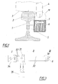
- Fig. 1 shows the section through a railroad track 1 and a cutout a located on the tread of the rail head 2 wheel 3 with the flange 4.
- a fastening device 5 of the wheel sensor 6 shown in section attached Close to the surface of the wheel sensor 6 is the sensor coil 7, whose magnetic field M itself spreads to the top. In the effective range of the magnetic field M arrives next to the Flange 4 and the rail head 2 of the rail 1. Both elements act on the sensor coil 7 damping one. If there is no wheel 3 with flange 4 in the Effective range of the sensor coil 7 is located, the rail head 2 remains as a partially damped Element present.
- Different forms of rail profiles, Tolerances in the roll profile and tolerances in the fastening device lead to significant differences in the degree of pre-damping of the sensor system, the must be compensated after installation.
- Core of the circuit of Fig. 2 is the resonant circuit 8, in the simplest Case consisting of a sensor coil 7 and a capacitor 9.
- An amplifier 10 with a drive line 11 and a feedback line 12 to the resonant circuit 8 forms the oscillator.
- the damping of the resonant circuit 8 changes the current consumption lo of the oscillator. This change in current consumption lo becomes according to the prior art for the notification of presence of a vehicle wheel evaluated.
- the wheel sensor circuit is for implementing the invention with others Facilities supplemented.
- a control module 13, preferably as Voltage regulator is formed, for that a microcontroller 14 and the amplifier 10 are supplied with constant voltage even if the Input voltage Uv / Ua changes greatly.
- the microcontroller 14 has at least two inputs 15, 16, and several outputs connected to the balancing switches 17 to 20 and the acknowledgment switch 21 act. These switches 17 to 21 may preferably be transistors be controllable with low power.
- the adjustment switches 17 to 20 are interconnect so that they depend on the control by the outputs of the microcontroller 17in are capable of passive devices 22 to 25 between coil connections or inductively coupled coil turns or shut down.
- the passive components 22 to 25 are in the embodiment drawn as resistors. As soon as such a component in the Coil connections is switched, the quality of the coil drops to about the same Way, as if the rail head continues in the magnetic field of the sensor coil would invade.
- the passive components 22 to 25 are capacitors. By connection or Shutdown changes the resonant frequency of the coil 7. In some sensor circuits This method can also be used as a match.
- the acknowledgment switch 21 is capable of depending on the drive by the microcontroller 14 to influence the sensor supply current Ig, in which a resistor 26 in series with a Zener diode 27 between the supply terminals the sensor circuit is switched. This effect can only occur when the supply voltage is greater than the voltage the zener diode 27.
- the circuit is supplied with the supply voltage Uv.
- the voltage Uv must be greater in consideration of the control function of the voltage regulator 13 its output voltage and about the same as the voltage value of the Zener diode 27. It flows the total sensor current Ig, which consists essentially of the Constant supply current Im of the microcontroller 14 and out of the variable Oscillator current lo composed. Since the entire supply voltage Ua Z-diode 27 drops, the input signal is over 15 in the microcontroller 14th Zero.
- the adjustment process is initiated by the supply voltage Uv raised to the value Ua by the external connection of a balancing device becomes. To avoid interference, it is advantageous if the tuning voltage Ua is significantly higher than the supply voltage Uv, for example twice as high.
- the input 15 of the microcontroller 14th Activated whereupon a program with approximately the following procedure is started:
- a temperature sensor 29 is still indicated, with a Input of the microcontroller 14 is connected.
- a temperature at the adjustment time corresponding value stored in the microcontroller 14, a temperature at the adjustment time corresponding value stored.
- the microcontroller 14 then changes Changes in the instantaneous temperature compared to the stored temperature value the memory values for the switch positions or acts on these memory values during the measurement with corresponding correction values, so that the previously possible temperature error is avoided. It can also be beneficial the circuit arrangement with the switches 17 to 20 and the adjustment elements 22 to 25 only for temperature compensation in otherwise balanced inductive sensors 8 to use. In the further description but will again mainly referred to the automatic total adjustment.
- Fig. 3 mean: I the system component indoor unit, II the cable route, the is usually designed in the form of an underground cable and III the track system.
- the track system III is usually a terminal box or track box 30, in which the wheel sensor cable is connected to the ground cable.
- the wheel sensor 6 is shown here as a variable impressed current source.
- the indoor unit I accommodates a cable termination device in most cases 31, the ground cable 32 and the indoor cable 33 on cable clamps leads.
- the indoor cable 33 is a rating and amplifier assembly 34, which both the power supply for the wheel sensor. 6 provides as well as the generated by the wheel sensor 6 analog signals and evaluates in the form of switching signals of the railway signaling system provides. Because of Of the known prior art does not need to be closer to the functions here such assemblies 34 will be received.
- the balancing device 35 can in principle at any point on the signal transmission path connected between wheel sensor 6 and evaluation module 34 become. Conveniently, the easily accessible and mostly open Terminal points on the cable termination 31 preferred. One more way exists at the terminal points of the track junction box 30.
- the connections of the balancing device 35 are galvanic directly with the sensor wires connected so that they are able, in addition to the power supply of Wheel sensor 6 to introduce voltage and current.
- Fig. 4 and Fig. 5 show examples, such as the adjustment process appropriate can expire.
- the sensor supply voltage U Plotted the horizontal axis t indicates the time course.
- the sequence, shown in Fig. 4 designed so that starting with the voltage curve On the left the standard supply voltage Uv is applied.
- the adjustment process starts by adjusting the voltage Ua on the cable wires aufschaltet.
- the wheel sensor starts the program matching, as under the Explanations of Fig. 2 described.
- the successful comparison eventually becomes acknowledged by a load of the balancing voltage Ua.
- the balancing device 35 can this acknowledgment is recognized because of the increase in power demand and the operator be made apparent.
- the range of Acknowledgment Q represented as a voltage dip, which is due to a certain Internal resistance of the balancing device 35 may result.
- the method of Figure 5 uses frequency information for alignment and acknowledgment, in contrast to the DC method of FIG. 4.
- the flow of information through Serial data words for example in the PWM process to accomplish. Because of The known prior art of such transmission methods must be here will not be discussed further.
- the transfer of various Adjustment commands or acknowledgment messages the information about the alignment process, its failure or further information about the condition of the wheel sensor 6 give.
- the microcontroller 14 has a Analog output 36, via which an adjustable voltage as a balancing voltage can be output, whose height is adjustable, with the setting values are stored and, moreover, as described in connection with FIG. 2 was, can be influenced by signals from a temperature sensor 29.
- a Temperature sensor 29 On the output 36 is between a resistor 37 and a corresponding one Impedance and a potential equalization condenser 39 a Capacitance diode 38 is turned on, their capacity by the applied reverse voltage is determined. The entire circuit is applied to the sensor coil 7.
Landscapes
- Engineering & Computer Science (AREA)
- Automation & Control Theory (AREA)
- Mechanical Engineering (AREA)
- Technology Law (AREA)
- Physics & Mathematics (AREA)
- General Physics & Mathematics (AREA)
- Train Traffic Observation, Control, And Security (AREA)
- Arrangements For Transmission Of Measured Signals (AREA)
- Electric Propulsion And Braking For Vehicles (AREA)
Priority Applications (2)
| Application Number | Priority Date | Filing Date | Title |
|---|---|---|---|
| SI200430557T SI1479587T1 (sl) | 2003-03-27 | 2004-03-16 | Stikalna naprava za nastavitev induktivnih senzorjev |
| PL04450066T PL1479587T3 (pl) | 2003-03-27 | 2004-03-16 | Układ połączeń do regulacji czujników indukcyjnych |
Applications Claiming Priority (2)
| Application Number | Priority Date | Filing Date | Title |
|---|---|---|---|
| AT4872003 | 2003-03-27 | ||
| AT0048703A AT413373B (de) | 2003-03-27 | 2003-03-27 | Schaltungsanordnung zum abgleichen von induktiven sensoren |
Publications (3)
| Publication Number | Publication Date |
|---|---|
| EP1479587A2 true EP1479587A2 (fr) | 2004-11-24 |
| EP1479587A3 EP1479587A3 (fr) | 2006-05-17 |
| EP1479587B1 EP1479587B1 (fr) | 2007-10-17 |
Family
ID=33034704
Family Applications (1)
| Application Number | Title | Priority Date | Filing Date |
|---|---|---|---|
| EP04450066A Expired - Lifetime EP1479587B1 (fr) | 2003-03-27 | 2004-03-16 | Circuit pour ajuster des capteurs inductifs |
Country Status (6)
| Country | Link |
|---|---|
| EP (1) | EP1479587B1 (fr) |
| AT (2) | AT413373B (fr) |
| DE (1) | DE502004005240D1 (fr) |
| ES (1) | ES2294454T3 (fr) |
| PL (1) | PL1479587T3 (fr) |
| SI (1) | SI1479587T1 (fr) |
Cited By (3)
| Publication number | Priority date | Publication date | Assignee | Title |
|---|---|---|---|---|
| WO2017186886A1 (fr) | 2016-04-28 | 2017-11-02 | Bombardier Transportation (Zwus) Polska Sp. Z.O.O. | Détecteur de roue pour détecter une roue de véhicule ferroviaire |
| EP3521131A1 (fr) * | 2018-02-06 | 2019-08-07 | Pintsch Tiefenbach GmbH | Senseur, système et procédé pour détecter des pièces métalliques |
| CN113264084A (zh) * | 2021-05-27 | 2021-08-17 | 海宁德科隆电子有限公司 | 轨道计轴传感器 |
Families Citing this family (2)
| Publication number | Priority date | Publication date | Assignee | Title |
|---|---|---|---|---|
| PL237272B1 (pl) | 2016-09-19 | 2021-03-22 | Voestalpine Signaling Sopot Spolka Z Ograniczona Odpowiedzialnoscia | Sposób i układ do strojenia czujników indukcyjnych do wykrywania obecności kół taboru szynowego |
| DE102022206169A1 (de) | 2022-06-21 | 2023-12-21 | Siemens Mobility GmbH | Sensor und Eisenbahngleisanlage mit Sensor |
Family Cites Families (4)
| Publication number | Priority date | Publication date | Assignee | Title |
|---|---|---|---|---|
| DE4132393C2 (de) * | 1991-09-26 | 1998-07-09 | Siemens Ag | Sensoreinrichtung für einen Schienenkontakt |
| DE4405039A1 (de) * | 1994-02-17 | 1995-08-24 | Sel Alcatel Ag | Achszähler mit änderbarer Schwellwerteinstellung |
| WO1999011497A1 (fr) * | 1997-09-04 | 1999-03-11 | L.B. Foster Company | Compteur de roues de chemin de fer et systemes de commande de blocs |
| DE19959233B4 (de) * | 1999-12-08 | 2007-12-13 | Tiefenbach Gmbh | Induktiver Sensor zum Erfassen von Metallteilen |
-
2003
- 2003-03-27 AT AT0048703A patent/AT413373B/de not_active IP Right Cessation
-
2004
- 2004-03-16 ES ES04450066T patent/ES2294454T3/es not_active Expired - Lifetime
- 2004-03-16 PL PL04450066T patent/PL1479587T3/pl unknown
- 2004-03-16 SI SI200430557T patent/SI1479587T1/sl unknown
- 2004-03-16 EP EP04450066A patent/EP1479587B1/fr not_active Expired - Lifetime
- 2004-03-16 AT AT04450066T patent/ATE375906T1/de active
- 2004-03-16 DE DE502004005240T patent/DE502004005240D1/de not_active Expired - Lifetime
Cited By (5)
| Publication number | Priority date | Publication date | Assignee | Title |
|---|---|---|---|---|
| WO2017186886A1 (fr) | 2016-04-28 | 2017-11-02 | Bombardier Transportation (Zwus) Polska Sp. Z.O.O. | Détecteur de roue pour détecter une roue de véhicule ferroviaire |
| US10875554B2 (en) | 2016-04-28 | 2020-12-29 | Bombardier Transportation (Zwus) Polska Sp. Z O. O. | Wheel detector for detecting a wheel of a rail vehicle |
| EP3521131A1 (fr) * | 2018-02-06 | 2019-08-07 | Pintsch Tiefenbach GmbH | Senseur, système et procédé pour détecter des pièces métalliques |
| DE102018102611A1 (de) | 2018-02-06 | 2019-08-08 | PINTSCH TIEFENBACH GmbH | Sensor, System und Verfahren zum Erfassen von Metallteilen |
| CN113264084A (zh) * | 2021-05-27 | 2021-08-17 | 海宁德科隆电子有限公司 | 轨道计轴传感器 |
Also Published As
| Publication number | Publication date |
|---|---|
| ATA4872003A (de) | 2005-07-15 |
| ES2294454T3 (es) | 2008-04-01 |
| PL1479587T3 (pl) | 2008-03-31 |
| EP1479587B1 (fr) | 2007-10-17 |
| ATE375906T1 (de) | 2007-11-15 |
| SI1479587T1 (sl) | 2008-02-29 |
| EP1479587A3 (fr) | 2006-05-17 |
| DE502004005240D1 (de) | 2007-11-29 |
| AT413373B (de) | 2006-02-15 |
Similar Documents
| Publication | Publication Date | Title |
|---|---|---|
| DE19723645B4 (de) | Anordnung zur Signalübertragung zwischen einer Geberstelle und einer Empfangsstelle | |
| EP1691320A1 (fr) | Circuit et procédé destinés à l'alimentation en tension d'un transpondeur | |
| DE19639974C2 (de) | Vorrichtung und Verfahren zum Umsetzen von manuellem auf automatischen Betrieb für einen automatisch bewegbaren Gegenstand eines Kraftfahrzeuges | |
| EP1748573A1 (fr) | Méthode pour la transmission de données entre une pompe et une entité de contrôle et pompe correspondante. | |
| EP2383622B1 (fr) | Dispositif de raccordement destiné au raccordement d'appareils de terrain | |
| DE102014206292A1 (de) | Elektroniksteuervorrichtung | |
| DE2505287A1 (de) | Auf eine aenderung eines magnetfeldes ansprechende anordnung | |
| DE69300242T2 (de) | Einrichtung zur Detektion der Durchfahrt eines Fahrzeuges mittels eines passiven Transponders. | |
| DE19959233B4 (de) | Induktiver Sensor zum Erfassen von Metallteilen | |
| EP1479587B1 (fr) | Circuit pour ajuster des capteurs inductifs | |
| DE102016211354A1 (de) | Sendereinrichtung, Sensoreinrichtung und Verfahren zum Erfassen einer Magnetfeldänderung | |
| EP1261882B1 (fr) | Dispositif destine a surveiller et a pronostiquer la probabilite de panne de detecteurs inductifs de proximite | |
| EP3776780A1 (fr) | Procédé et dispositif de détection d'un court-circuit entre spires dans des enroulements disposés en parallèle | |
| EP1203933B1 (fr) | Dispositif capteur pour la mesure d'au moins une grandeur | |
| DE102010009576A1 (de) | Induktiver Nährungsschalter | |
| EP3521131B1 (fr) | Senseur, système et procédé pour détecter des pièces métalliques | |
| EP0126958A2 (fr) | Détecteur pour l'enregistrement des données d'un objet en mouvement | |
| EP1845548A2 (fr) | Dispositif, circuit et procédé destinés à la surveillance de l'isolation et du raccordement à la terre dans un système informatique | |
| DE102020113289A1 (de) | Kontaktlose Energie- und/oder Datenübertragung | |
| DE102006035598B4 (de) | Verfahren zur Detektion des Belegt- oder Freizustandes eines Gleisabschnittes | |
| EP1512937A2 (fr) | Dispositif pour déterminer la position d'un élément d'un véhicule par rapport à un deuxième élément, en particulier pour déterminer le tangage d'un véhicule, et véhicule équipé d'un tel dispositif | |
| DE19718388B4 (de) | Signalverarbeitungseinheit für eine Steuereinrichtung eines Stangenstromabnehmerschalters | |
| EP4016206B1 (fr) | Agencement de capteur, appareil de commande, système d'automatisation et procédé de transmission des signaux selon deux normes de communication | |
| DE19644920B4 (de) | Einrichtung zur Erkennung der Position eines Stellelementes eines Stellgliedes | |
| DE20022841U1 (de) | Vorrichtung zur Bewegungserfassung |
Legal Events
| Date | Code | Title | Description |
|---|---|---|---|
| PUAI | Public reference made under article 153(3) epc to a published international application that has entered the european phase |
Free format text: ORIGINAL CODE: 0009012 |
|
| AK | Designated contracting states |
Kind code of ref document: A2 Designated state(s): AT BE BG CH CY CZ DE DK EE ES FI FR GB GR HU IE IT LI LU MC NL PL PT RO SE SI SK TR |
|
| AX | Request for extension of the european patent |
Extension state: AL HR LT LV MK |
|
| PUAL | Search report despatched |
Free format text: ORIGINAL CODE: 0009013 |
|
| AK | Designated contracting states |
Kind code of ref document: A3 Designated state(s): AT BE BG CH CY CZ DE DK EE ES FI FR GB GR HU IE IT LI LU MC NL PL PT RO SE SI SK TR |
|
| AX | Request for extension of the european patent |
Extension state: AL LT LV MK |
|
| RIC1 | Information provided on ipc code assigned before grant |
Ipc: B61L 1/08 20060101ALI20060328BHEP Ipc: B61L 1/16 20060101AFI20041005BHEP |
|
| 17P | Request for examination filed |
Effective date: 20060801 |
|
| AKX | Designation fees paid |
Designated state(s): AT BE BG CH CY CZ DE DK EE ES FI FR GB GR HU IE IT LI LU MC NL PL PT RO SE SI SK TR |
|
| GRAP | Despatch of communication of intention to grant a patent |
Free format text: ORIGINAL CODE: EPIDOSNIGR1 |
|
| GRAS | Grant fee paid |
Free format text: ORIGINAL CODE: EPIDOSNIGR3 |
|
| GRAA | (expected) grant |
Free format text: ORIGINAL CODE: 0009210 |
|
| AK | Designated contracting states |
Kind code of ref document: B1 Designated state(s): AT BE BG CH CY CZ DE DK EE ES FI FR GB GR HU IE IT LI LU MC NL PL PT RO SE SI SK TR |
|
| REG | Reference to a national code |
Ref country code: GB Ref legal event code: FG4D Free format text: NOT ENGLISH |
|
| REG | Reference to a national code |
Ref country code: CH Ref legal event code: EP |
|
| REG | Reference to a national code |
Ref country code: IE Ref legal event code: FG4D Free format text: LANGUAGE OF EP DOCUMENT: GERMAN |
|
| REF | Corresponds to: |
Ref document number: 502004005240 Country of ref document: DE Date of ref document: 20071129 Kind code of ref document: P |
|
| REG | Reference to a national code |
Ref country code: CH Ref legal event code: NV Representative=s name: E. BLUM & CO. AG PATENT- UND MARKENANWAELTE VSP |
|
| REG | Reference to a national code |
Ref country code: SE Ref legal event code: TRGR |
|
| GBT | Gb: translation of ep patent filed (gb section 77(6)(a)/1977) |
Effective date: 20080115 |
|
| REG | Reference to a national code |
Ref country code: PL Ref legal event code: T3 |
|
| REG | Reference to a national code |
Ref country code: ES Ref legal event code: FG2A Ref document number: 2294454 Country of ref document: ES Kind code of ref document: T3 |
|
| PG25 | Lapsed in a contracting state [announced via postgrant information from national office to epo] |
Ref country code: PT Free format text: LAPSE BECAUSE OF FAILURE TO SUBMIT A TRANSLATION OF THE DESCRIPTION OR TO PAY THE FEE WITHIN THE PRESCRIBED TIME-LIMIT Effective date: 20080317 Ref country code: BG Free format text: LAPSE BECAUSE OF FAILURE TO SUBMIT A TRANSLATION OF THE DESCRIPTION OR TO PAY THE FEE WITHIN THE PRESCRIBED TIME-LIMIT Effective date: 20080117 |
|
| REG | Reference to a national code |
Ref country code: IE Ref legal event code: FD4D |
|
| ET | Fr: translation filed | ||
| REG | Reference to a national code |
Ref country code: HU Ref legal event code: AG4A Ref document number: E003041 Country of ref document: HU |
|
| PG25 | Lapsed in a contracting state [announced via postgrant information from national office to epo] |
Ref country code: DK Free format text: LAPSE BECAUSE OF FAILURE TO SUBMIT A TRANSLATION OF THE DESCRIPTION OR TO PAY THE FEE WITHIN THE PRESCRIBED TIME-LIMIT Effective date: 20071017 |
|
| PLBE | No opposition filed within time limit |
Free format text: ORIGINAL CODE: 0009261 |
|
| STAA | Information on the status of an ep patent application or granted ep patent |
Free format text: STATUS: NO OPPOSITION FILED WITHIN TIME LIMIT |
|
| PG25 | Lapsed in a contracting state [announced via postgrant information from national office to epo] |
Ref country code: RO Free format text: LAPSE BECAUSE OF FAILURE TO SUBMIT A TRANSLATION OF THE DESCRIPTION OR TO PAY THE FEE WITHIN THE PRESCRIBED TIME-LIMIT Effective date: 20071017 |
|
| 26N | No opposition filed |
Effective date: 20080718 |
|
| PG25 | Lapsed in a contracting state [announced via postgrant information from national office to epo] |
Ref country code: IE Free format text: LAPSE BECAUSE OF FAILURE TO SUBMIT A TRANSLATION OF THE DESCRIPTION OR TO PAY THE FEE WITHIN THE PRESCRIBED TIME-LIMIT Effective date: 20071017 Ref country code: MC Free format text: LAPSE BECAUSE OF NON-PAYMENT OF DUE FEES Effective date: 20080331 |
|
| PG25 | Lapsed in a contracting state [announced via postgrant information from national office to epo] |
Ref country code: EE Free format text: LAPSE BECAUSE OF FAILURE TO SUBMIT A TRANSLATION OF THE DESCRIPTION OR TO PAY THE FEE WITHIN THE PRESCRIBED TIME-LIMIT Effective date: 20071017 Ref country code: GR Free format text: LAPSE BECAUSE OF FAILURE TO SUBMIT A TRANSLATION OF THE DESCRIPTION OR TO PAY THE FEE WITHIN THE PRESCRIBED TIME-LIMIT Effective date: 20080118 |
|
| PG25 | Lapsed in a contracting state [announced via postgrant information from national office to epo] |
Ref country code: FI Free format text: LAPSE BECAUSE OF FAILURE TO SUBMIT A TRANSLATION OF THE DESCRIPTION OR TO PAY THE FEE WITHIN THE PRESCRIBED TIME-LIMIT Effective date: 20071017 |
|
| REG | Reference to a national code |
Ref country code: CH Ref legal event code: PUE Owner name: FRAUSCHER HOLDING GMBH Free format text: FRAUSCHER, JOSEF, ING.#GEWERBESTRASSE 1#4774 ST. MARIENKIRCHEN (AT) -TRANSFER TO- FRAUSCHER HOLDING GMBH#GEWERBESTRASSE 1#4774 ST. MARIENKIRCHEN (AT) |
|
| REG | Reference to a national code |
Ref country code: GB Ref legal event code: 732E Free format text: REGISTERED BETWEEN 20090423 AND 20090429 |
|
| REG | Reference to a national code |
Ref country code: SI Ref legal event code: SP73 Owner name: FRAUSCHER HOLDING GMBH; AT Effective date: 20090430 |
|
| NLS | Nl: assignments of ep-patents |
Owner name: FRAUSCHER HOLDING GMBH Effective date: 20090507 |
|
| PG25 | Lapsed in a contracting state [announced via postgrant information from national office to epo] |
Ref country code: CY Free format text: LAPSE BECAUSE OF FAILURE TO SUBMIT A TRANSLATION OF THE DESCRIPTION OR TO PAY THE FEE WITHIN THE PRESCRIBED TIME-LIMIT Effective date: 20071017 |
|
| REG | Reference to a national code |
Ref country code: FR Ref legal event code: TP |
|
| REG | Reference to a national code |
Ref country code: ES Ref legal event code: PC2A |
|
| REG | Reference to a national code |
Ref country code: HU Ref legal event code: GB9C Owner name: FRAUSCHER HOLDING GMBH, AT Free format text: FORMER OWNER(S): FRAUSCHER, JOSEF, AT Ref country code: HU Ref legal event code: FH1C Free format text: FORMER REPRESENTATIVE(S): MESTER TAMAS, SWORKS NEMZETKOEZI SZABADALMI UEGYVIVOEI IRODA KFT., HU Representative=s name: MESTER TAMAS SZABADALMI UEGYVIVOE, SWORKS NEMZ, HU |
|
| PG25 | Lapsed in a contracting state [announced via postgrant information from national office to epo] |
Ref country code: LU Free format text: LAPSE BECAUSE OF NON-PAYMENT OF DUE FEES Effective date: 20080316 |
|
| PG25 | Lapsed in a contracting state [announced via postgrant information from national office to epo] |
Ref country code: TR Free format text: LAPSE BECAUSE OF FAILURE TO SUBMIT A TRANSLATION OF THE DESCRIPTION OR TO PAY THE FEE WITHIN THE PRESCRIBED TIME-LIMIT Effective date: 20071017 |
|
| REG | Reference to a national code |
Ref country code: FR Ref legal event code: PLFP Year of fee payment: 12 |
|
| REG | Reference to a national code |
Ref country code: FR Ref legal event code: PLFP Year of fee payment: 13 |
|
| REG | Reference to a national code |
Ref country code: CH Ref legal event code: PUE Owner name: FRAUSCHER SENSORTECHNIK HOLDING GMBH, AT Free format text: FORMER OWNER: FRAUSCHER HOLDING GMBH, AT |
|
| REG | Reference to a national code |
Ref country code: DE Ref legal event code: R082 Ref document number: 502004005240 Country of ref document: DE Representative=s name: ZWICKER SCHNAPPAUF & PARTNER PATENTANWAELTE PA, DE Ref country code: DE Ref legal event code: R082 Ref document number: 502004005240 Country of ref document: DE Representative=s name: MEISSNER BOLTE PATENTANWAELTE RECHTSANWAELTE P, DE Ref country code: DE Ref legal event code: R082 Ref document number: 502004005240 Country of ref document: DE Representative=s name: BARTELS UND PARTNER PATENTANWAELTE, DE Ref country code: DE Ref legal event code: R081 Ref document number: 502004005240 Country of ref document: DE Owner name: FRAUSCHER SENSORTECHNIK HOLDING GMBH, AT Free format text: FORMER OWNER: FRAUSCHER HOLDING GMBH, ST. MARIENKIRCHEN, AT Ref country code: DE Ref legal event code: R082 Ref document number: 502004005240 Country of ref document: DE Representative=s name: ZSP PATENTANWAELTE PARTG MBB, DE Ref country code: DE Ref legal event code: R081 Ref document number: 502004005240 Country of ref document: DE Owner name: FRAUSCHER SENSORTECHNIK GMBH, AT Free format text: FORMER OWNER: FRAUSCHER HOLDING GMBH, ST. MARIENKIRCHEN, AT |
|
| REG | Reference to a national code |
Ref country code: NL Ref legal event code: PD Owner name: FRAUSCHER SENSORTECHNIK HOLDING GMBH; AT Free format text: DETAILS ASSIGNMENT: VERANDERING VAN EIGENAAR(S), OVERDRACHT; FORMER OWNER NAME: FRAUSCHER HOLDING GMBH Effective date: 20160919 |
|
| REG | Reference to a national code |
Ref country code: ES Ref legal event code: PC2A Owner name: FRAUSCHER SENSORTECHNIK HOLDING GMBH Effective date: 20161018 |
|
| REG | Reference to a national code |
Ref country code: HU Ref legal event code: GB9C Owner name: FRAUSCHER SENSORTECHNIK HOLDING GMBH, AT Free format text: FORMER OWNER(S): FRAUSCHER HOLDING GMBH, AT; FRAUSCHER, JOSEF, AT Ref country code: SI Ref legal event code: SP73 Owner name: FRAUSCHER SENSORTECHNIK HOLDING GMBH; AT Effective date: 20160914 |
|
| REG | Reference to a national code |
Ref country code: GB Ref legal event code: 732E Free format text: REGISTERED BETWEEN 20161020 AND 20161026 |
|
| REG | Reference to a national code |
Ref country code: SK Ref legal event code: PC4A Ref document number: E 2926 Country of ref document: SK Owner name: FRAUSCHER SENSORTECHNIK HOLDING GMBH, ST. MARI, AT Free format text: FORMER OWNER: FRAUSCHER HOLDING GMBH, ST. MARIENKIRCHEN, AT Effective date: 20160825 |
|
| REG | Reference to a national code |
Ref country code: FR Ref legal event code: TP Owner name: FRAUSCHER SENSORTECHKNIK HOLDING GMBH, AT Effective date: 20161125 |
|
| REG | Reference to a national code |
Ref country code: AT Ref legal event code: PC Ref document number: 375906 Country of ref document: AT Kind code of ref document: T Owner name: FRAUSCHER SENSORTECHNIK HOLDING GMBH, AT Effective date: 20161209 |
|
| REG | Reference to a national code |
Ref country code: FR Ref legal event code: PLFP Year of fee payment: 14 |
|
| REG | Reference to a national code |
Ref country code: DE Ref legal event code: R082 Ref document number: 502004005240 Country of ref document: DE Representative=s name: ZWICKER SCHNAPPAUF & PARTNER PATENTANWAELTE PA, DE Ref country code: DE Ref legal event code: R082 Ref document number: 502004005240 Country of ref document: DE Representative=s name: MEISSNER BOLTE PATENTANWAELTE RECHTSANWAELTE P, DE Ref country code: DE Ref legal event code: R082 Ref document number: 502004005240 Country of ref document: DE Representative=s name: ZSP PATENTANWAELTE PARTG MBB, DE |
|
| REG | Reference to a national code |
Ref country code: DE Ref legal event code: R082 Ref document number: 502004005240 Country of ref document: DE Representative=s name: ZWICKER SCHNAPPAUF & PARTNER PATENTANWAELTE PA, DE Ref country code: DE Ref legal event code: R082 Ref document number: 502004005240 Country of ref document: DE Representative=s name: ZSP PATENTANWAELTE PARTG MBB, DE |
|
| REG | Reference to a national code |
Ref country code: FR Ref legal event code: PLFP Year of fee payment: 15 |
|
| REG | Reference to a national code |
Ref country code: CH Ref legal event code: PFUS Owner name: FRAUSCHER SENSORTECHNIK GMBH, AT Free format text: FORMER OWNER: FRAUSCHER SENSORTECHNIK HOLDING GMBH, AT |
|
| REG | Reference to a national code |
Ref country code: DE Ref legal event code: R082 Ref document number: 502004005240 Country of ref document: DE Representative=s name: ZWICKER SCHNAPPAUF & PARTNER PATENTANWAELTE PA, DE Ref country code: DE Ref legal event code: R082 Ref document number: 502004005240 Country of ref document: DE Representative=s name: ZSP PATENTANWAELTE PARTG MBB, DE Ref country code: DE Ref legal event code: R081 Ref document number: 502004005240 Country of ref document: DE Owner name: FRAUSCHER SENSORTECHNIK GMBH, AT Free format text: FORMER OWNER: FRAUSCHER SENSORTECHNIK HOLDING GMBH, ST. MARIENKIRCHEN, AT |
|
| REG | Reference to a national code |
Ref country code: BE Ref legal event code: PD Owner name: FRAUSCHER SENSORTECHNIK HOLDING GMBH; AT Free format text: DETAILS ASSIGNMENT: CHANGE OF OWNER(S), AFFECTATION / CESSION; FORMER OWNER NAME: FRAUSCHER HOLDING GMBH Effective date: 20160909 Ref country code: BE Ref legal event code: PD Owner name: FRAUSCHER SENSORTECHNIK GMBH; AT Free format text: DETAILS ASSIGNMENT: CHANGE OF OWNER(S), FUSION; FORMER OWNER NAME: FRAUSCHER SENSORTECHNIK HOLDING GMBH Effective date: 20181114 |
|
| REG | Reference to a national code |
Ref country code: ES Ref legal event code: PC2A Owner name: FRAUSCHER SENSORTECHNIK GMBH Effective date: 20181218 |
|
| REG | Reference to a national code |
Ref country code: GB Ref legal event code: 732E Free format text: REGISTERED BETWEEN 20181206 AND 20181212 |
|
| REG | Reference to a national code |
Ref country code: NL Ref legal event code: PD Owner name: FRAUSCHER SENSORTECHNIK GMBH; AT Free format text: DETAILS ASSIGNMENT: CHANGE OF OWNER(S), MERGE; FORMER OWNER NAME: FRAUSCHER SENSORTECHNIK HOLDING GMBH Effective date: 20181119 |
|
| REG | Reference to a national code |
Ref country code: SI Ref legal event code: SP73 Owner name: FRAUSCHER SENSORTECHNIK GMBH; AT Effective date: 20181219 |
|
| REG | Reference to a national code |
Ref country code: HU Ref legal event code: GB9C Owner name: FRAUSCHER SENSORTECHNIK GMBH, AT Free format text: FORMER OWNER(S): FRAUSCHER HOLDING GMBH, AT; FRAUSCHER SENSORTECHNIK HOLDING GMBH, AT; FRAUSCHER, JOSEF, AT |
|
| REG | Reference to a national code |
Ref country code: AT Ref legal event code: PC Ref document number: 375906 Country of ref document: AT Kind code of ref document: T Owner name: FRAUSCHER SENSORTECHNIK GMBH, AT Effective date: 20190123 |
|
| REG | Reference to a national code |
Ref country code: SK Ref legal event code: TC4A Ref document number: E 2926 Country of ref document: SK Owner name: FRAUSCHER SENSORTECHNIK GMBH, ST. MARIENKIRCHE, AT Effective date: 20190425 |
|
| REG | Reference to a national code |
Ref country code: SK Ref legal event code: PC4A Ref document number: E 2926 Country of ref document: SK Owner name: FRAUSCHER SENSORTECHNIK GMBH, ST. MARIENKIRCHE, AT Free format text: FORMER OWNER: FRAUSCHER SENSORTECHNIK HOLDING GMBH, ST. MARIENKIRCHEN/SCHAERDING, AT Effective date: 20190814 |
|
| REG | Reference to a national code |
Ref country code: DE Ref legal event code: R082 Ref document number: 502004005240 Country of ref document: DE Representative=s name: ZWICKER SCHNAPPAUF & PARTNER PATENTANWAELTE PA, DE |
|
| PGFP | Annual fee paid to national office [announced via postgrant information from national office to epo] |
Ref country code: FR Payment date: 20230323 Year of fee payment: 20 Ref country code: CZ Payment date: 20230316 Year of fee payment: 20 Ref country code: AT Payment date: 20230321 Year of fee payment: 20 |
|
| PGFP | Annual fee paid to national office [announced via postgrant information from national office to epo] |
Ref country code: SK Payment date: 20230227 Year of fee payment: 20 Ref country code: SI Payment date: 20230224 Year of fee payment: 20 Ref country code: SE Payment date: 20230317 Year of fee payment: 20 Ref country code: PL Payment date: 20230217 Year of fee payment: 20 Ref country code: IT Payment date: 20230321 Year of fee payment: 20 Ref country code: HU Payment date: 20230227 Year of fee payment: 20 Ref country code: GB Payment date: 20230321 Year of fee payment: 20 Ref country code: DE Payment date: 20230328 Year of fee payment: 20 Ref country code: BE Payment date: 20230323 Year of fee payment: 20 |
|
| P01 | Opt-out of the competence of the unified patent court (upc) registered |
Effective date: 20230506 |
|
| PGFP | Annual fee paid to national office [announced via postgrant information from national office to epo] |
Ref country code: NL Payment date: 20230323 Year of fee payment: 20 |
|
| PGFP | Annual fee paid to national office [announced via postgrant information from national office to epo] |
Ref country code: ES Payment date: 20230424 Year of fee payment: 20 Ref country code: CH Payment date: 20230402 Year of fee payment: 20 |
|
| REG | Reference to a national code |
Ref country code: DE Ref legal event code: R071 Ref document number: 502004005240 Country of ref document: DE |
|
| REG | Reference to a national code |
Ref country code: NL Ref legal event code: MK Effective date: 20240315 |
|
| REG | Reference to a national code |
Ref country code: ES Ref legal event code: FD2A Effective date: 20240327 |
|
| REG | Reference to a national code |
Ref country code: CH Ref legal event code: PL |
|
| REG | Reference to a national code |
Ref country code: BE Ref legal event code: MK Effective date: 20240316 |
|
| REG | Reference to a national code |
Ref country code: GB Ref legal event code: PE20 Expiry date: 20240315 Ref country code: SK Ref legal event code: MK4A Ref document number: E 2926 Country of ref document: SK Expiry date: 20240316 |
|
| PG25 | Lapsed in a contracting state [announced via postgrant information from national office to epo] |
Ref country code: ES Free format text: LAPSE BECAUSE OF EXPIRATION OF PROTECTION Effective date: 20240317 |
|
| PG25 | Lapsed in a contracting state [announced via postgrant information from national office to epo] |
Ref country code: ES Free format text: LAPSE BECAUSE OF EXPIRATION OF PROTECTION Effective date: 20240317 Ref country code: CZ Free format text: LAPSE BECAUSE OF EXPIRATION OF PROTECTION Effective date: 20240316 Ref country code: SK Free format text: LAPSE BECAUSE OF EXPIRATION OF PROTECTION Effective date: 20240316 Ref country code: GB Free format text: LAPSE BECAUSE OF EXPIRATION OF PROTECTION Effective date: 20240315 |
|
| REG | Reference to a national code |
Ref country code: SE Ref legal event code: EUG |
|
| PG25 | Lapsed in a contracting state [announced via postgrant information from national office to epo] |
Ref country code: SI Free format text: LAPSE BECAUSE OF EXPIRATION OF PROTECTION Effective date: 20240317 |
|
| REG | Reference to a national code |
Ref country code: AT Ref legal event code: MK07 Ref document number: 375906 Country of ref document: AT Kind code of ref document: T Effective date: 20240316 |
|
| PG25 | Lapsed in a contracting state [announced via postgrant information from national office to epo] |
Ref country code: SI Free format text: LAPSE BECAUSE OF EXPIRATION OF PROTECTION Effective date: 20240317 |