EP1479602A2 - Hinteres Endstück mit Einsatzteilen - Google Patents
Hinteres Endstück mit Einsatzteilen Download PDFInfo
- Publication number
- EP1479602A2 EP1479602A2 EP04076488A EP04076488A EP1479602A2 EP 1479602 A2 EP1479602 A2 EP 1479602A2 EP 04076488 A EP04076488 A EP 04076488A EP 04076488 A EP04076488 A EP 04076488A EP 1479602 A2 EP1479602 A2 EP 1479602A2
- Authority
- EP
- European Patent Office
- Prior art keywords
- slot
- pad member
- fixed pad
- rear fork
- packing piece
- Prior art date
- Legal status (The legal status is an assumption and is not a legal conclusion. Google has not performed a legal analysis and makes no representation as to the accuracy of the status listed.)
- Granted
Links
Images
Classifications
-
- B—PERFORMING OPERATIONS; TRANSPORTING
- B62—LAND VEHICLES FOR TRAVELLING OTHERWISE THAN ON RAILS
- B62K—CYCLES; CYCLE FRAMES; CYCLE STEERING DEVICES; RIDER-OPERATED TERMINAL CONTROLS SPECIALLY ADAPTED FOR CYCLES; CYCLE AXLE SUSPENSIONS; CYCLE SIDECARS, FORECARS, OR THE LIKE
- B62K25/00—Axle suspensions
- B62K25/02—Axle suspensions for mounting axles rigidly on cycle frame or fork, e.g. adjustably
Definitions
- the invention relates to a rear fork pad system according to the introductory portion of claim 1.
- the invention further relates to rear fork pads composed therewith according to the introductory portions of claims 2 and 6.
- Such a rear fork pad system and such rear fork pads are known from practice.
- the bicycle frame can be equipped with different driving systems as desired.
- One possibility that is desired in many cases is for the bicycle to be equipped with a derailleur gearing system with a spring-loaded chain adjuster, comprising a pivoting arm with chain diverting rollers which, energized by spring force, keeps the chain tensioned and, upon shifting gear, accommodates the change in the circumference of the blade or the set of sprockets over which the chain runs.
- Other options that are often desirable for the same frame are a gearing system without spring-loaded chain adjuster or a fixed transmission ratio, that is, without gearing system with different transmission ratios between which gear shifts can be made.
- the chain is tensioned by suitably choosing the position of the axle of the rear wheel in the slots in the rear pads, optionally with the aid of an adjustable, rigid chain adjuster, as described, for instance, in the Dutch patent application 8600479.
- the rear wheel is pulled backwards to tension the chain and subsequently nuts are tightened onto the rear axle ends, so that the rear pads are clamped between those nuts and fixed portions of the rear wheel bearing.
- the right-hand rear pad is composed of a fixed pad member and:
- a disadvantage of such a system is that the rear wheel, if the bicycle is provided with a spring-loaded chain adjuster, during mounting in the rear fork, needs to be pulled against the spring force exerted on the chain by the chain adjuster, towards the rear end of the bicycle and needs to be retained in order to have the axle reliably abut against the closed ends of the slots when securing the clamping elements.
- rear fork pad system according to claim 1.
- the invention can also be embodied in rear fork pads according to claims 2 and 6 which constitute alternative rear fork pads to be composed with the system according to claim 1, as well as in a rear fork according to claim 12 and a bicycle frame according to claim 15 which are provided with such rear fork pads.
- the rear wheel of a bicycle with a spring-loaded chain adjuster and associated packing piece or associated packing pieces does not need to be pulled rearwards to the end of the slot in the fixed pad member in order to bring the axle of the rear wheel into abutment with a stop which defines the position of the rear axle in the driving direction of the bicycle.
- a bicycle without spring-loaded chain adjuster composed starting from the rear fork pad system according to the invention, the second portion of the slot bounded by the packing piece or the packing pieces - which second portion forms a continuation of the slot in inter alia the fixed pad member - ensures that the total length of the slot in the rear pad provides a sufficiently large adjusting range for tensioning the chain.
- the packing piece or the packing pieces for use without a chain adjuster forms or form the boundary of a slot portion in line with the slot in the fixed pad member, such boundary can be omitted wholly or partly if the other packing piece or the other packing pieces intended for use with a spring-loaded chain adjuster is or are mounted. Therefore, when mounting and demounting a rear axle, it does not need to be passed along a boundary of a slot portion which is not needed when a spring-loaded chain adjuster is used.
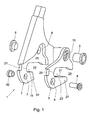
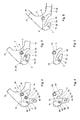
- the rear pad 1, shown in the drawing, according to Figs. 1, 3, 5 and 6 and the rear pad 51 according to Figs. 2, 4 and 6 are rear pads of an example of a rear pad system according to the invention.
- the rear pad system shown is made up of a fixed rear pad member 2 which is the same for both designs of the rear pads 1, 51 to be composed with this system, and different packing pieces 3 and 53, respectively.
- the rear pad system further comprises fastening elements 4, 5, 6, 32.
- these fastening elements are designed as an internal wrenching bolt 4 and a sleeved nut 32, for fastening through a hole 7 in the fixed pad member 2 and through a hole 8, 58 in the packing piece 3, 53, and further as an internal wrenching bolt 5 and a sleeved nut 6, for fastening through holes 9, 10, 60 in the fixed pad member 2 and the packing piece 3 and 53, respectively.
- the rear pad system serves for composing rear pads on the right-hand side of the rear wheel, or at least the side where the spring-loaded chain adjuster is mounted.
- the packing piece 53 is provided with an arm 61 having therein a mounting hole 62.
- the fixed pad member 2 or the packing piece 53 may be provided with further holes for receiving fastening elements of the spring-loaded chain adjuster.
- the parts for composing an associated rear pad on the left-hand side of the rear wheel form, with respect to the central median plane of the bicycle, a mirrored copy of the rear pads 1, 51 shown. This also holds for the parts 3-6.
- An exception to this is the packing piece 53 for use in combination with a derailleur gearing system with spring-loaded chain adjuster.
- the associated packing piece for composing the rear pad on the left-hand side of the rear wheel is not provided with an arm 61 for fastening the spring-loaded chain adjuster, but instead of that arm 61 has a contour of a configuration as is indicated with a chain-dotted line 63.
- a rear fork pad 1 to be composed with the rear fork pad system according to the invention, for a bicycle without spring-loaded chain adjuster, is described in more detail with reference to the example of a rear pad 1 shown in Figs. 1 and 3.
- Figs. 5 and 6 show the packing piece and the fixed packing member of such a rear fork pad 1 separately.
- the fixed pad member 2 which is identical for both kinds of rear fork pads 3, 53 to be composed with the rear fork pad system according to the invention, has mounting portions in the form of lips 14, 15 for attachment to legs 17, 18 (see Fig. 6) of a rear fork of a bicycle.
- a slot 19 with an open end 20 and a closed end 21 is recessed, for receiving a portion of a rear wheel axle 22 which extends transversely to and through the slot 19.
- the packing piece 3 bounds a slot 23 having an open end 24 and a closed end 25, likewise for receiving a portion of a rear wheel axle 22.
- the slot 23 is moreover recessed in the packing piece 3. It is also possible, however, that the packing piece bounds the slot wholly or partly on just one side, for instance the underside. In mounted condition, the packing piece 3 lies along a contact surface against the fixed pad member 2 to be clamped with the fixed pad member 2 between a clamping element and a stop on the axle 22 which extends through the slot 23 in the packing piece 3.
- the fixed pad member 2 and the packing piece 3 are designed for positioning the packing piece 3 relative to the fixed pad member 2.
- the fixed pad member 2 is provided with a recess 26.
- the fixed pad member 2 has a thickness which is less than the rest, or at least surrounding portions, of the fixed pad member 2.
- the depth of the recess 26 corresponds to the thickness of the packing piece 3, so that the rear pad 1 upon placement of the packing piece 3 is as thick in the area of the recess 26 in the fixed pad member 2 as in surrounding portions of the fixed pad member 2.
- the contour of the recess 26 in the fixed pad member 2 closely conforms to the contour of the packing piece 3, so that the latter in mounted condition is held accurately positioned in the recess 26.
- the fastening elements 4-6 can serve as dowel pins for positioning the packing piece 3 relative to the fixed pad member in cooperation with the holes 7-10 in the fixed pad member 2 and in the packing piece 3.
- the fastening elements further serve for keeping the packing piece 3 in place against the fixed pad member 2 if the rear wheel is not mounted in the rear fork.
- the slot 19 in the fixed pad member 2 and a first portion of the slot 23 in the packing piece 3 remote from the open end 24 of the slot 23 in the packing piece 3 form a common slot portion.
- the slot 19, 23 has sufficient length to provide an adjusting range for the position of the rear axle 22 in the driving direction of the bicycle, which enables the chain to be tensioned sufficiently.
- the fixed pad member 2 bounds only a first portion 19 of the slot 19, 23 contiguous to the closed end 21, and the second portion of the slot 23, at least on one side, is bounded exclusively by the packing piece 3.
- an area contiguous to the slot 23 - according to this example under the nominal position of the rear axle 22 - is cleared. Via this cleared area, when using the alternative packing piece 53 - in which case adjustability in the pull direction of the chain is not needed - a rear wheel can be fitted more easily.
- the packing piece 3 has a free, projecting leg 27 which in operating position forms a lower boundary of the slot 23 in the packing pieces 3, and which extends alongside and beyond the underside of leg 30 of the fixed pad member 2, bounding the slot 19.
- This is particularly advantageous because especially by taking out the rear wheel axle downwards from the mounted position, or by mounting it in upward direction to the intended position in the rear fork pads, a rear wheel can be particularly simply mounted and demounted, respectively.
- FIG. 51 intended for bicycles having a gearing system with spring-loaded chain adjuster, which can be composed starting from the same fixed pad member 2 but through combination with the other packing piece 53, is shown in Fig. 2.
- Figs. 4 and 6 show the packing piece and the fixed pad member 2 separately.
- the packing piece 53 bounds a second slot 73 having an open end 74 and a closed end 75. In mounted condition, this packing piece 53 also extends along a contact surface against the fixed pad member 2, to be clamped with the fixed pad member 2 between a clamping member and a stop on the rear wheel axle 22 which extends through the slot 73 which is bounded by the packing piece 53.
- the fixed pad member 2 and the packing piece 53 are designed for positioning the packing piece 53 relative to the fixed pad member 2 by means of a closely conforming fit of the packing piece 53 in the recess 26 and optionally supplemented by a dowel pin effect of the fastening elements 4-6 relative to the holes 7-10.
- the packing piece 53 covers the greater part of the slot 19 in the fixed pad member 2 for keeping the axle 22 received in the rear fork pad 51 spaced from the end 21 of the slot 19 in the fixed pad member 2.
- the axle 22 does not need to be pulled backwards as far as the end 21 of the slot 19, which facilitates mounting.
- displacement in the opposite direction away from the end 21 of the slot 19 during demounting is not necessary anymore.
- the position of the axle 22 in mounted condition corresponds better to the nominal position of the axle 22 when using a gearing system without spring-loaded chain adjuster, where the chain prevents the rear wheel axle 22 being pulled all the way against the end 21 of the slot 19.
- the leg 27 forms the only lower boundary of a portion of the slot 23 contiguous to the open end 24, in which the axle 22 is situated, the leg 30 of the fixed pad member 2, which extends along the slot 19, is relatively short.
- the leg 30 of the fixed pad member 2 situated under the slot 19 thus impedes removal and fitting of the rear wheel axle 22 at the least considerably less than would be the case if this leg were to extend to a point near the open end 24 of the slot 23 in the rear pad 1 according to Figs. 1 and 3.
- the slot 74 in the packing piece 53 extends at an angle relative to the slot 19 in the fixed pad member 2.
- the rear wheel of the bicycle can be readily fitted by lowering the bicycle, with the slot 73 above the rear axle 22, downwards until the axle 22 abuts against the end 75 of the slot 73.
- the position of the axle 22 in the pull direction of the chain is then determined by the position of the end 75 of the slot 73, against which the axle 22, due to the weight of the bicycle, remains lodged inherently and reliably. It is therefore not necessary to keep the rear axle 22 positioned against the closed end 75 of the slot 73 by hand until the clamping elements for clamping the rear pads have been operated.
- the slot 73 in the packing piece 53, in the service position extends approximately vertically downwards from the closed end 75 thereof. This is also advantageous when taking out the rear wheel, because upon lifting the bicycle by the rear end thereof, with the clamping elements of the rear wheel axle removed, the rear wheel axle will generally move of itself out of the rear fork pads 51.
- the closed end 75 of the slot 73 in the packing piece 53 for use in combination with a spring-loaded chain adjuster is situated at a distance from the position where centerlines of the slots in the fixed pad member 2 and in this packing piece 53 intersect, that is equal to half of the width of the slot 73 in this packing piece 53, the centerline of a rear wheel axle 22 in the end position in the slot 73 in this packing piece 53 also intersects the centerline of the slot 19 in the fixed pad member 2.
- the centerline of a wheel in a rear fork pad 51 with packing piece 53 for use in combination with a spring-loaded chain adjuster just like the centerline of a wheel in a rear fork pad 1 with packing piece 3 intended for use without spring-loaded chain adjuster, will lie in a plane defined by the centerline of the slot 19 in the fixed pad member 2. Accordingly, the position of the rear wheel in the frame when using one packing piece 3 will correspond to a large extent with the position of the rear wheel when using the other packing piece 53.
- the fixed pad member 2 is a plate extending in a plane, with a contour seen in a view transverse to that plane.
- the packing piece 3 or 53 extends in a plane parallel to the plane in which the planar pad member 2 extends. Seen in a view transverse to those planes, the packing pieces 3, 53 also each have a contour. In an area where the contour of the packing piece 3 or 53 projects outside the contour of the fixed pad member, the packing pieces each have thickened portions 31, 81, 82, 83. These thickened portions form a filling in line with the fixed pad member 2 within the contour of the respective packing piece, so that an improved strength is realized and the packing piece 3, 53 is more accurately clamped between the respective clamping element and the fixed part of the rear wheel hub.
- two of the thickened portions 31, 81 of the packing pieces 3, 53 form a filling bounding, or situated in, the first slot 19 in the fixed pad member 2 and within the second contour, so that the supporting surface of the rear fork pads against the rear axle is enlarged.
- the packing piece 53 which is intended for supporting a derailleur arm, further has thickened portions 82, 83 along an edge of the fixed pad member 2 that is remote from the slot for receiving the rear axle 3, which portions are contiguous to the fixed pad member 2. These thickenings 82 and 83 thus contribute to a reliable fixation of the packing piece 53 relative to the fixed pad member 2.
- the rear fork pads according to the invention are preferably applied on both sides of the rear fork, in order to enable the wheel, when using a spring-loaded chain adjuster, to be mounted easily, and, without use of a spring-loaded chain adjuster, to obtain on both sides of the rear fork a rear pad with a sufficiently long slot for adjusting the rear axle in the pull direction of the chain.
- a bicycle frame can be finished with or without a gearing system with spring-loaded chain adjuster, as desired, while on the one hand, in case the bicycle is finished without a gearing system with spring-loaded chain adjuster, a sufficient adjustability of the rear axle in horizontal direction is obtained for tensioning the chain, and on the other hand, in case the bicycle is finished with a gearing system with spring-loaded chain adjuster, a rear wheel mountability and demountability that is simple for the user in particular is realized, which is equal to that of frames with rear pads which are exclusively designed to be finished with a gearing system with spring-loaded chain adjuster.
- the packing pieces instead of being mounted on the outsides of the fixed pad portions, can also be mounted on the insides of the fixed pad portions. This makes it possible, for instance, by using packing pieces that have such a thickness that the assembled rear fork pad, at least in a partial area within the contour, has a greater thickness than outside the contour of the packing piece, to adjust the distance between the rear fork pads, so that mounting rear wheels with hubs of different axial formats is made possible without bending the rear fork.
- the fixed pad members can have, for instance, a constant thickness, that is, can be designed without deepened portions for wholly or partly accommodating the thickness of the packing pieces.
Landscapes
- Engineering & Computer Science (AREA)
- Mechanical Engineering (AREA)
- Axle Suspensions And Sidecars For Cycles (AREA)
- Packaging Of Machine Parts And Wound Products (AREA)
Applications Claiming Priority (2)
| Application Number | Priority Date | Filing Date | Title |
|---|---|---|---|
| NL1023459A NL1023459C2 (nl) | 2003-05-19 | 2003-05-19 | Achtervorkpadden met opvulstukken. |
| NL1023459 | 2003-05-19 |
Publications (3)
| Publication Number | Publication Date |
|---|---|
| EP1479602A2 true EP1479602A2 (de) | 2004-11-24 |
| EP1479602A3 EP1479602A3 (de) | 2007-11-28 |
| EP1479602B1 EP1479602B1 (de) | 2012-02-15 |
Family
ID=33095828
Family Applications (1)
| Application Number | Title | Priority Date | Filing Date |
|---|---|---|---|
| EP04076488A Expired - Lifetime EP1479602B1 (de) | 2003-05-19 | 2004-05-19 | Hinteres Endstück mit Einsatzteilen |
Country Status (4)
| Country | Link |
|---|---|
| EP (1) | EP1479602B1 (de) |
| AT (1) | ATE545575T1 (de) |
| DE (1) | DE202004021407U1 (de) |
| NL (1) | NL1023459C2 (de) |
Cited By (7)
| Publication number | Priority date | Publication date | Assignee | Title |
|---|---|---|---|---|
| ES2255449A1 (es) * | 2004-12-15 | 2006-06-16 | Orbea S. Coop. Ltda. | Pata trasera para bicicleta. |
| DE202009004819U1 (de) * | 2009-05-14 | 2010-10-14 | Rose Versand Gmbh | Fahrradachsbefestigungssystem |
| ITPD20090179A1 (it) * | 2009-06-19 | 2010-12-20 | Cicli Esperia S P A | Elemento a forcella per il collegamento di una ruota ad un telaio di una bicicletta |
| ES2369287A1 (es) * | 2011-08-11 | 2011-11-29 | Orbea S. Coop. | Conjunto-cuadro para construir un cuadro de bicicleta cuya puntera permite el montaje de diferentes tipos de eje rueda. |
| US8424894B2 (en) * | 2009-08-21 | 2013-04-23 | Speedhound Design Bureau, Llc | Bicycle frame dropouts and methods |
| EP2716534A1 (de) * | 2012-10-05 | 2014-04-09 | Fisher Outdoor Leisure Limited | Ausfallendesystem für eine Hinterrahmenanordnung eines Fahrrads |
| EP2842859A1 (de) * | 2013-08-28 | 2015-03-04 | Winora-Staiger GmbH | Fahrradrahmen aus faserverstärktem Werkstoff mit Adapterplatten für das Hinterrad |
Families Citing this family (1)
| Publication number | Priority date | Publication date | Assignee | Title |
|---|---|---|---|---|
| DE202015104466U1 (de) * | 2015-08-24 | 2016-11-25 | Rose Bikes Gmbh | Fahrradachsbefestigungssystem |
Citations (1)
| Publication number | Priority date | Publication date | Assignee | Title |
|---|---|---|---|---|
| NL8600479A (nl) | 1986-02-26 | 1987-09-16 | Batavus Intercycle Bv | Kettingspanner voor het traploos spannen van de ketting van een van uitvalasopnemers voorziene fiets. |
Family Cites Families (7)
| Publication number | Priority date | Publication date | Assignee | Title |
|---|---|---|---|---|
| FR562618A (fr) * | 1922-10-24 | 1923-11-15 | Patte arrière pour vélos et motos | |
| US4805941A (en) * | 1985-06-10 | 1989-02-21 | Huffy Corporation | Quick release wheel retainer |
| IT207484Z2 (it) * | 1986-03-26 | 1988-01-18 | Gios Flli Snc | Forcellino per ruota posteriore per biciclette particolarmente da competizione |
| US4856802A (en) * | 1988-10-12 | 1989-08-15 | Schilplin Frederick C | Dropout assembly |
| JPH0281292U (de) * | 1988-12-13 | 1990-06-22 | ||
| US5020819A (en) * | 1989-10-02 | 1991-06-04 | Cannondale Corporation | Replaceable derailleur hanger |
| DE9104109U1 (de) * | 1991-04-05 | 1992-07-30 | Allmendinger, Eugen, Dipl.-Ing.(FH), 7950 Biberach | Befestigung von Achsen in Ausfallenden aus Kunststoff |
-
2003
- 2003-05-19 NL NL1023459A patent/NL1023459C2/nl not_active IP Right Cessation
-
2004
- 2004-05-19 EP EP04076488A patent/EP1479602B1/de not_active Expired - Lifetime
- 2004-05-19 DE DE202004021407U patent/DE202004021407U1/de not_active Expired - Lifetime
- 2004-05-19 AT AT04076488T patent/ATE545575T1/de active
Patent Citations (1)
| Publication number | Priority date | Publication date | Assignee | Title |
|---|---|---|---|---|
| NL8600479A (nl) | 1986-02-26 | 1987-09-16 | Batavus Intercycle Bv | Kettingspanner voor het traploos spannen van de ketting van een van uitvalasopnemers voorziene fiets. |
Cited By (11)
| Publication number | Priority date | Publication date | Assignee | Title |
|---|---|---|---|---|
| ES2255449A1 (es) * | 2004-12-15 | 2006-06-16 | Orbea S. Coop. Ltda. | Pata trasera para bicicleta. |
| EP1671878A3 (de) * | 2004-12-15 | 2006-09-06 | Orbea, S. Coop. Ltda. | Ende einer Hinterradgabel für ein Fahrrad |
| ES2255449B1 (es) * | 2004-12-15 | 2007-12-01 | Orbea S. Coop. Ltda. | Pata trasera para bicicleta. |
| DE202009004819U1 (de) * | 2009-05-14 | 2010-10-14 | Rose Versand Gmbh | Fahrradachsbefestigungssystem |
| ITPD20090179A1 (it) * | 2009-06-19 | 2010-12-20 | Cicli Esperia S P A | Elemento a forcella per il collegamento di una ruota ad un telaio di una bicicletta |
| US8424894B2 (en) * | 2009-08-21 | 2013-04-23 | Speedhound Design Bureau, Llc | Bicycle frame dropouts and methods |
| ES2369287A1 (es) * | 2011-08-11 | 2011-11-29 | Orbea S. Coop. | Conjunto-cuadro para construir un cuadro de bicicleta cuya puntera permite el montaje de diferentes tipos de eje rueda. |
| EP2557029A1 (de) * | 2011-08-11 | 2013-02-13 | Orbea, S. Coop. Ltda. | Fahrradrahmensatz zum Bau eines Fahrradrahmens mit einem hinteren Ausfallende, das den Einbau verschiedener Radachsen erlaubt |
| EP2716534A1 (de) * | 2012-10-05 | 2014-04-09 | Fisher Outdoor Leisure Limited | Ausfallendesystem für eine Hinterrahmenanordnung eines Fahrrads |
| EP2842859A1 (de) * | 2013-08-28 | 2015-03-04 | Winora-Staiger GmbH | Fahrradrahmen aus faserverstärktem Werkstoff mit Adapterplatten für das Hinterrad |
| US9545971B2 (en) | 2013-08-28 | 2017-01-17 | Winora-Staiger Gmbh | Bicycle frame made out of fiber-reinforced material comprising an adapter plate for the rear wheel |
Also Published As
| Publication number | Publication date |
|---|---|
| ATE545575T1 (de) | 2012-03-15 |
| EP1479602B1 (de) | 2012-02-15 |
| EP1479602A3 (de) | 2007-11-28 |
| NL1023459C2 (nl) | 2004-11-22 |
| DE202004021407U1 (de) | 2007-12-20 |
Similar Documents
| Publication | Publication Date | Title |
|---|---|---|
| CA1077079A (en) | Convertible tricycle | |
| CA2294437C (en) | Fender having element conforming to mounting bracket | |
| US4591179A (en) | Bar steps for a small-sized vehicle | |
| EP1479602B1 (de) | Hinteres Endstück mit Einsatzteilen | |
| US6322148B1 (en) | Vehicle seat connection assembly | |
| US20110316251A1 (en) | Bicycle Sliding Dropout with Lockable Slider | |
| CA2578878C (en) | Track extension for vehicle track systems and method | |
| US5096215A (en) | Fork end of a bicycle | |
| JP2013252784A (ja) | リヤエンドおよびそれを用いた自転車 | |
| US20050120822A1 (en) | Bicycle control cable fixing device | |
| US20030171175A1 (en) | Bicycle rear derailleur | |
| US20090023528A1 (en) | Motorcycle Chain Guide and Tensioner | |
| JPH0660593U (ja) | 自転車用のリヤディレーラ用ブラケット | |
| FR2642024A1 (fr) | Porte-bicyclettes reglable et verrouillable adaptable a tout type de cycles fixe sur l'attelage arriere des vehicules automobiles | |
| AU725168B3 (en) | Mounting device for mounting a front wheel axle on a stroller frame | |
| US20030205600A1 (en) | Transit bracket assembly for motorcycles | |
| CA2545835A1 (en) | System for converting a recreational vehicle | |
| EP0965369B1 (de) | Bindungselement fur einen alpinen Ski mit abnehmbarer Bremse | |
| FR2959183A1 (fr) | Ensemble comprenant un pare-choc et deux feux arrieres et des moyens pour fixer ces derniers au pare-choc, et vehicule equipe d'un tel ensemble | |
| JP3691555B2 (ja) | 自転車用付属部品取付構造 | |
| FR2626259A1 (fr) | Raclette, notamment pour convoyeur a chaines a raclettes a bande a double chaine centrale | |
| JP4879610B2 (ja) | 自転車用サイドスタンド | |
| JP2004299467A (ja) | 乗用型田植機 | |
| JPH0742949Y2 (ja) | 自動2輪車のリヤアクスル仮受機構 | |
| JPH0751989Y2 (ja) | 一輪車の補助輪取付具 |
Legal Events
| Date | Code | Title | Description |
|---|---|---|---|
| PUAI | Public reference made under article 153(3) epc to a published international application that has entered the european phase |
Free format text: ORIGINAL CODE: 0009012 |
|
| AK | Designated contracting states |
Kind code of ref document: A2 Designated state(s): AT BE BG CH CY CZ DE DK EE ES FI FR GB GR HU IE IT LI LU MC NL PL PT RO SE SI SK TR |
|
| AX | Request for extension of the european patent |
Extension state: AL HR LT LV MK |
|
| PUAL | Search report despatched |
Free format text: ORIGINAL CODE: 0009013 |
|
| AK | Designated contracting states |
Kind code of ref document: A3 Designated state(s): AT BE BG CH CY CZ DE DK EE ES FI FR GB GR HU IE IT LI LU MC NL PL PT RO SE SI SK TR |
|
| AX | Request for extension of the european patent |
Extension state: AL HR LT LV MK |
|
| 17P | Request for examination filed |
Effective date: 20080526 |
|
| AKX | Designation fees paid |
Designated state(s): AT BE BG CH CY CZ DE DK EE ES FI FR GB GR HU IE IT LI LU MC NL PL PT RO SE SI SK TR |
|
| 17Q | First examination report despatched |
Effective date: 20100521 |
|
| GRAP | Despatch of communication of intention to grant a patent |
Free format text: ORIGINAL CODE: EPIDOSNIGR1 |
|
| GRAS | Grant fee paid |
Free format text: ORIGINAL CODE: EPIDOSNIGR3 |
|
| GRAA | (expected) grant |
Free format text: ORIGINAL CODE: 0009210 |
|
| AK | Designated contracting states |
Kind code of ref document: B1 Designated state(s): AT BE BG CH CY CZ DE DK EE ES FI FR GB GR HU IE IT LI LU MC NL PL PT RO SE SI SK TR |
|
| REG | Reference to a national code |
Ref country code: CH Ref legal event code: EP Ref country code: GB Ref legal event code: FG4D |
|
| REG | Reference to a national code |
Ref country code: IE Ref legal event code: FG4D |
|
| REG | Reference to a national code |
Ref country code: AT Ref legal event code: REF Ref document number: 545575 Country of ref document: AT Kind code of ref document: T Effective date: 20120315 |
|
| REG | Reference to a national code |
Ref country code: DE Ref legal event code: R096 Ref document number: 602004036493 Country of ref document: DE Effective date: 20120412 |
|
| REG | Reference to a national code |
Ref country code: NL Ref legal event code: T3 |
|
| PG25 | Lapsed in a contracting state [announced via postgrant information from national office to epo] |
Ref country code: PL Free format text: LAPSE BECAUSE OF FAILURE TO SUBMIT A TRANSLATION OF THE DESCRIPTION OR TO PAY THE FEE WITHIN THE PRESCRIBED TIME-LIMIT Effective date: 20120215 Ref country code: BE Free format text: LAPSE BECAUSE OF FAILURE TO SUBMIT A TRANSLATION OF THE DESCRIPTION OR TO PAY THE FEE WITHIN THE PRESCRIBED TIME-LIMIT Effective date: 20120215 Ref country code: FI Free format text: LAPSE BECAUSE OF FAILURE TO SUBMIT A TRANSLATION OF THE DESCRIPTION OR TO PAY THE FEE WITHIN THE PRESCRIBED TIME-LIMIT Effective date: 20120215 Ref country code: GR Free format text: LAPSE BECAUSE OF FAILURE TO SUBMIT A TRANSLATION OF THE DESCRIPTION OR TO PAY THE FEE WITHIN THE PRESCRIBED TIME-LIMIT Effective date: 20120516 Ref country code: PT Free format text: LAPSE BECAUSE OF FAILURE TO SUBMIT A TRANSLATION OF THE DESCRIPTION OR TO PAY THE FEE WITHIN THE PRESCRIBED TIME-LIMIT Effective date: 20120615 |
|
| REG | Reference to a national code |
Ref country code: AT Ref legal event code: MK05 Ref document number: 545575 Country of ref document: AT Kind code of ref document: T Effective date: 20120215 |
|
| PG25 | Lapsed in a contracting state [announced via postgrant information from national office to epo] |
Ref country code: CY Free format text: LAPSE BECAUSE OF FAILURE TO SUBMIT A TRANSLATION OF THE DESCRIPTION OR TO PAY THE FEE WITHIN THE PRESCRIBED TIME-LIMIT Effective date: 20120215 |
|
| PG25 | Lapsed in a contracting state [announced via postgrant information from national office to epo] |
Ref country code: SI Free format text: LAPSE BECAUSE OF FAILURE TO SUBMIT A TRANSLATION OF THE DESCRIPTION OR TO PAY THE FEE WITHIN THE PRESCRIBED TIME-LIMIT Effective date: 20120215 Ref country code: RO Free format text: LAPSE BECAUSE OF FAILURE TO SUBMIT A TRANSLATION OF THE DESCRIPTION OR TO PAY THE FEE WITHIN THE PRESCRIBED TIME-LIMIT Effective date: 20120215 Ref country code: CZ Free format text: LAPSE BECAUSE OF FAILURE TO SUBMIT A TRANSLATION OF THE DESCRIPTION OR TO PAY THE FEE WITHIN THE PRESCRIBED TIME-LIMIT Effective date: 20120215 Ref country code: SE Free format text: LAPSE BECAUSE OF FAILURE TO SUBMIT A TRANSLATION OF THE DESCRIPTION OR TO PAY THE FEE WITHIN THE PRESCRIBED TIME-LIMIT Effective date: 20120215 Ref country code: DK Free format text: LAPSE BECAUSE OF FAILURE TO SUBMIT A TRANSLATION OF THE DESCRIPTION OR TO PAY THE FEE WITHIN THE PRESCRIBED TIME-LIMIT Effective date: 20120215 Ref country code: EE Free format text: LAPSE BECAUSE OF FAILURE TO SUBMIT A TRANSLATION OF THE DESCRIPTION OR TO PAY THE FEE WITHIN THE PRESCRIBED TIME-LIMIT Effective date: 20120215 |
|
| PG25 | Lapsed in a contracting state [announced via postgrant information from national office to epo] |
Ref country code: IT Free format text: LAPSE BECAUSE OF FAILURE TO SUBMIT A TRANSLATION OF THE DESCRIPTION OR TO PAY THE FEE WITHIN THE PRESCRIBED TIME-LIMIT Effective date: 20120215 Ref country code: SK Free format text: LAPSE BECAUSE OF FAILURE TO SUBMIT A TRANSLATION OF THE DESCRIPTION OR TO PAY THE FEE WITHIN THE PRESCRIBED TIME-LIMIT Effective date: 20120215 |
|
| REG | Reference to a national code |
Ref country code: NL Ref legal event code: V1 Effective date: 20121201 |
|
| PLBE | No opposition filed within time limit |
Free format text: ORIGINAL CODE: 0009261 |
|
| STAA | Information on the status of an ep patent application or granted ep patent |
Free format text: STATUS: NO OPPOSITION FILED WITHIN TIME LIMIT |
|
| PG25 | Lapsed in a contracting state [announced via postgrant information from national office to epo] |
Ref country code: MC Free format text: LAPSE BECAUSE OF NON-PAYMENT OF DUE FEES Effective date: 20120531 |
|
| REG | Reference to a national code |
Ref country code: CH Ref legal event code: PL |
|
| 26N | No opposition filed |
Effective date: 20121116 |
|
| GBPC | Gb: european patent ceased through non-payment of renewal fee |
Effective date: 20120519 |
|
| PG25 | Lapsed in a contracting state [announced via postgrant information from national office to epo] |
Ref country code: LI Free format text: LAPSE BECAUSE OF NON-PAYMENT OF DUE FEES Effective date: 20120531 Ref country code: CH Free format text: LAPSE BECAUSE OF NON-PAYMENT OF DUE FEES Effective date: 20120531 Ref country code: AT Free format text: LAPSE BECAUSE OF FAILURE TO SUBMIT A TRANSLATION OF THE DESCRIPTION OR TO PAY THE FEE WITHIN THE PRESCRIBED TIME-LIMIT Effective date: 20120215 |
|
| REG | Reference to a national code |
Ref country code: IE Ref legal event code: MM4A |
|
| REG | Reference to a national code |
Ref country code: FR Ref legal event code: ST Effective date: 20130131 |
|
| REG | Reference to a national code |
Ref country code: DE Ref legal event code: R119 Ref document number: 602004036493 Country of ref document: DE Effective date: 20121201 Ref country code: DE Ref legal event code: R097 Ref document number: 602004036493 Country of ref document: DE Effective date: 20121116 |
|
| PG25 | Lapsed in a contracting state [announced via postgrant information from national office to epo] |
Ref country code: NL Free format text: LAPSE BECAUSE OF NON-PAYMENT OF DUE FEES Effective date: 20121201 |
|
| PG25 | Lapsed in a contracting state [announced via postgrant information from national office to epo] |
Ref country code: GB Free format text: LAPSE BECAUSE OF NON-PAYMENT OF DUE FEES Effective date: 20120519 Ref country code: IE Free format text: LAPSE BECAUSE OF NON-PAYMENT OF DUE FEES Effective date: 20120519 Ref country code: FR Free format text: LAPSE BECAUSE OF NON-PAYMENT OF DUE FEES Effective date: 20120531 Ref country code: ES Free format text: LAPSE BECAUSE OF FAILURE TO SUBMIT A TRANSLATION OF THE DESCRIPTION OR TO PAY THE FEE WITHIN THE PRESCRIBED TIME-LIMIT Effective date: 20120526 |
|
| PG25 | Lapsed in a contracting state [announced via postgrant information from national office to epo] |
Ref country code: DE Free format text: LAPSE BECAUSE OF NON-PAYMENT OF DUE FEES Effective date: 20121201 |
|
| PG25 | Lapsed in a contracting state [announced via postgrant information from national office to epo] |
Ref country code: BG Free format text: LAPSE BECAUSE OF FAILURE TO SUBMIT A TRANSLATION OF THE DESCRIPTION OR TO PAY THE FEE WITHIN THE PRESCRIBED TIME-LIMIT Effective date: 20120515 |
|
| PG25 | Lapsed in a contracting state [announced via postgrant information from national office to epo] |
Ref country code: TR Free format text: LAPSE BECAUSE OF FAILURE TO SUBMIT A TRANSLATION OF THE DESCRIPTION OR TO PAY THE FEE WITHIN THE PRESCRIBED TIME-LIMIT Effective date: 20120215 |
|
| PG25 | Lapsed in a contracting state [announced via postgrant information from national office to epo] |
Ref country code: LU Free format text: LAPSE BECAUSE OF NON-PAYMENT OF DUE FEES Effective date: 20120519 |
|
| PG25 | Lapsed in a contracting state [announced via postgrant information from national office to epo] |
Ref country code: HU Free format text: LAPSE BECAUSE OF FAILURE TO SUBMIT A TRANSLATION OF THE DESCRIPTION OR TO PAY THE FEE WITHIN THE PRESCRIBED TIME-LIMIT Effective date: 20040519 |