EP1479652B1 - Verfahren und Vorrichtung zur Herstellung eines Abgas-Entstickungsmittels - Google Patents
Verfahren und Vorrichtung zur Herstellung eines Abgas-Entstickungsmittels Download PDFInfo
- Publication number
- EP1479652B1 EP1479652B1 EP03405330A EP03405330A EP1479652B1 EP 1479652 B1 EP1479652 B1 EP 1479652B1 EP 03405330 A EP03405330 A EP 03405330A EP 03405330 A EP03405330 A EP 03405330A EP 1479652 B1 EP1479652 B1 EP 1479652B1
- Authority
- EP
- European Patent Office
- Prior art keywords
- ammonia
- carbon dioxide
- reactor
- urea
- water
- Prior art date
- Legal status (The legal status is an assumption and is not a legal conclusion. Google has not performed a legal analysis and makes no representation as to the accuracy of the status listed.)
- Expired - Lifetime
Links
Images

Classifications
-
- F—MECHANICAL ENGINEERING; LIGHTING; HEATING; WEAPONS; BLASTING
- F01—MACHINES OR ENGINES IN GENERAL; ENGINE PLANTS IN GENERAL; STEAM ENGINES
- F01N—GAS-FLOW SILENCERS OR EXHAUST APPARATUS FOR MACHINES OR ENGINES IN GENERAL; GAS-FLOW SILENCERS OR EXHAUST APPARATUS FOR INTERNAL-COMBUSTION ENGINES
- F01N3/00—Exhaust or silencing apparatus having means for purifying, rendering innocuous, or otherwise treating exhaust
- F01N3/08—Exhaust or silencing apparatus having means for purifying, rendering innocuous, or otherwise treating exhaust for rendering innocuous
- F01N3/10—Exhaust or silencing apparatus having means for purifying, rendering innocuous, or otherwise treating exhaust for rendering innocuous by thermal or catalytic conversion of noxious components of exhaust
- F01N3/18—Exhaust or silencing apparatus having means for purifying, rendering innocuous, or otherwise treating exhaust for rendering innocuous by thermal or catalytic conversion of noxious components of exhaust characterised by methods of operation; Control
- F01N3/20—Exhaust or silencing apparatus having means for purifying, rendering innocuous, or otherwise treating exhaust for rendering innocuous by thermal or catalytic conversion of noxious components of exhaust characterised by methods of operation; Control specially adapted for catalytic conversion
- F01N3/206—Adding periodically or continuously substances to exhaust gases for promoting purification, e.g. catalytic material in liquid form, NOx reducing agents
- F01N3/2066—Selective catalytic reduction [SCR]
-
- B—PERFORMING OPERATIONS; TRANSPORTING
- B01—PHYSICAL OR CHEMICAL PROCESSES OR APPARATUS IN GENERAL
- B01D—SEPARATION
- B01D53/00—Separation of gases or vapours; Recovering vapours of volatile solvents from gases; Chemical or biological purification of waste gases, e.g. engine exhaust gases, smoke, fumes, flue gases, aerosols
- B01D53/34—Chemical or biological purification of waste gases
- B01D53/92—Chemical or biological purification of waste gases of engine exhaust gases
- B01D53/94—Chemical or biological purification of waste gases of engine exhaust gases by catalytic processes
- B01D53/9404—Removing only nitrogen compounds
- B01D53/9409—Nitrogen oxides
- B01D53/9431—Processes characterised by a specific device
-
- C—CHEMISTRY; METALLURGY
- C01—INORGANIC CHEMISTRY
- C01C—AMMONIA; CYANOGEN; COMPOUNDS THEREOF
- C01C1/00—Ammonia; Compounds thereof
- C01C1/02—Preparation, purification or separation of ammonia
- C01C1/022—Preparation of aqueous ammonia solutions, i.e. ammonia water
-
- C—CHEMISTRY; METALLURGY
- C01—INORGANIC CHEMISTRY
- C01C—AMMONIA; CYANOGEN; COMPOUNDS THEREOF
- C01C1/00—Ammonia; Compounds thereof
- C01C1/02—Preparation, purification or separation of ammonia
- C01C1/08—Preparation of ammonia from nitrogenous organic substances
-
- C—CHEMISTRY; METALLURGY
- C01—INORGANIC CHEMISTRY
- C01F—COMPOUNDS OF THE METALS BERYLLIUM, MAGNESIUM, ALUMINIUM, CALCIUM, STRONTIUM, BARIUM, RADIUM, THORIUM, OR OF THE RARE-EARTH METALS
- C01F11/00—Compounds of calcium, strontium, or barium
- C01F11/18—Carbonates
-
- F—MECHANICAL ENGINEERING; LIGHTING; HEATING; WEAPONS; BLASTING
- F01—MACHINES OR ENGINES IN GENERAL; ENGINE PLANTS IN GENERAL; STEAM ENGINES
- F01N—GAS-FLOW SILENCERS OR EXHAUST APPARATUS FOR MACHINES OR ENGINES IN GENERAL; GAS-FLOW SILENCERS OR EXHAUST APPARATUS FOR INTERNAL-COMBUSTION ENGINES
- F01N2240/00—Combination or association of two or more different exhaust treating devices, or of at least one such device with an auxiliary device, not covered by indexing codes F01N2230/00 or F01N2250/00, one of the devices being
- F01N2240/25—Combination or association of two or more different exhaust treating devices, or of at least one such device with an auxiliary device, not covered by indexing codes F01N2230/00 or F01N2250/00, one of the devices being an ammonia generator
-
- F—MECHANICAL ENGINEERING; LIGHTING; HEATING; WEAPONS; BLASTING
- F01—MACHINES OR ENGINES IN GENERAL; ENGINE PLANTS IN GENERAL; STEAM ENGINES
- F01N—GAS-FLOW SILENCERS OR EXHAUST APPARATUS FOR MACHINES OR ENGINES IN GENERAL; GAS-FLOW SILENCERS OR EXHAUST APPARATUS FOR INTERNAL-COMBUSTION ENGINES
- F01N2610/00—Adding substances to exhaust gases
- F01N2610/02—Adding substances to exhaust gases the substance being ammonia or urea
-
- Y—GENERAL TAGGING OF NEW TECHNOLOGICAL DEVELOPMENTS; GENERAL TAGGING OF CROSS-SECTIONAL TECHNOLOGIES SPANNING OVER SEVERAL SECTIONS OF THE IPC; TECHNICAL SUBJECTS COVERED BY FORMER USPC CROSS-REFERENCE ART COLLECTIONS [XRACs] AND DIGESTS
- Y02—TECHNOLOGIES OR APPLICATIONS FOR MITIGATION OR ADAPTATION AGAINST CLIMATE CHANGE
- Y02A—TECHNOLOGIES FOR ADAPTATION TO CLIMATE CHANGE
- Y02A50/00—TECHNOLOGIES FOR ADAPTATION TO CLIMATE CHANGE in human health protection, e.g. against extreme weather
- Y02A50/20—Air quality improvement or preservation, e.g. vehicle emission control or emission reduction by using catalytic converters
-
- Y—GENERAL TAGGING OF NEW TECHNOLOGICAL DEVELOPMENTS; GENERAL TAGGING OF CROSS-SECTIONAL TECHNOLOGIES SPANNING OVER SEVERAL SECTIONS OF THE IPC; TECHNICAL SUBJECTS COVERED BY FORMER USPC CROSS-REFERENCE ART COLLECTIONS [XRACs] AND DIGESTS
- Y02—TECHNOLOGIES OR APPLICATIONS FOR MITIGATION OR ADAPTATION AGAINST CLIMATE CHANGE
- Y02P—CLIMATE CHANGE MITIGATION TECHNOLOGIES IN THE PRODUCTION OR PROCESSING OF GOODS
- Y02P20/00—Technologies relating to chemical industry
- Y02P20/151—Reduction of greenhouse gas [GHG] emissions, e.g. CO2
-
- Y—GENERAL TAGGING OF NEW TECHNOLOGICAL DEVELOPMENTS; GENERAL TAGGING OF CROSS-SECTIONAL TECHNOLOGIES SPANNING OVER SEVERAL SECTIONS OF THE IPC; TECHNICAL SUBJECTS COVERED BY FORMER USPC CROSS-REFERENCE ART COLLECTIONS [XRACs] AND DIGESTS
- Y02—TECHNOLOGIES OR APPLICATIONS FOR MITIGATION OR ADAPTATION AGAINST CLIMATE CHANGE
- Y02T—CLIMATE CHANGE MITIGATION TECHNOLOGIES RELATED TO TRANSPORTATION
- Y02T10/00—Road transport of goods or passengers
- Y02T10/10—Internal combustion engine [ICE] based vehicles
- Y02T10/12—Improving ICE efficiencies
Definitions
- the invention relates to a method and a device according to the preambles the corresponding independent claims.
- Method and device used to prepare an ammonia-containing exhaust gas denitrification the is particularly suitable, nitrogen oxides in exhaust gases of diesel engines by selective to remove catalytic reduction (SCR).
- a major problem in air pollution control is the fight against nitrogen oxides (NO x ).
- Important sources of nitrogen oxides are diesel engines.
- a technology known in diesel engines for combating nitrogen oxides is the SCR process, in which the nitrogen oxides are destroyed in the exhaust gas after injection of ammonia in a selective catalytic reduction.
- the problem with this process is that ammonia is toxic and strict safety precautions must be observed when handling and storing it, especially when it is clean.
- urea is used as a reducing agent.
- the urea is introduced into the exhaust gas stream and decomposes thermally there to ammonia gas and carbon dioxide.
- the kinetics of this thermal urea cleavage is so slow that the process is not applicable to small diesel engines, especially diesel vehicles.
- the gas mixture is directly in the exhaust gas stream introduced and passed with the exhaust gas through a catalyst where the ammonia Reduces nitrogen oxides and carbon dioxide has no special function, but also does not bother.
- the advantage of this method is that although the ammonia as highly concentrated gas can be used for the reduction, in this form but not stored, but is produced directly for consumption.
- a controlled dosage of ammonia addition according to the needs of Diesel engines with highly dynamic load profiles, such as diesel-powered Vehicles typical, but is not possible in this way.
- the invention now has the task of providing a method and a device create, with which it is possible in a simple manner, by an example starting from enzymatic or thermal cleavage of urea ammonia-containing exhaust gas removal agent to produce, in particular for the Denitrification of exhaust gases from diesel engines is more suitable and easier than that gaseous ammonia can be stored or carried in a vehicle and it always allows for the dosage according to highly dynamic load profiles to keep at least a minimum amount of denitrant ready.
- the Carbon dioxide in the medium for example, by forming a sparingly soluble Compound (e.g., calcium carbonate or other alkaline earth carbonate) becomes.
- a sparingly soluble Compound e.g., calcium carbonate or other alkaline earth carbonate
- ammonia water such a medium directly in the urea solution, whereby the carbon dioxide from the Ammonia water is precipitated.
- the resulting ammonia water is then advantageously concentrated by distillation, the precipitated, sparingly soluble compound remains.
- the advantage of the method according to the invention is, in particular, that the denitrification agent (carbon dioxide-free ammonia water) can be produced without refueling with ammonia as described in the introduction, and that it can nevertheless be kept ready in a storage container without problems, in variable quantities to be available per unit of time.
- the process according to the invention is supplied with safer urea and water and periodically removed ammonia water as needed and the set CO 2 .
- An apparatus for carrying out the method thus has a first reactor for the urea cleavage on and a second reactor for the production of the Amoniakwassers from the resulting in the urea cleavage ammonia (Introduction of ammonia in water).
- the first reactor has an inlet for Urea and water, the second an entrance for water and an exit for Ammonia water on.
- the two reactors are for a passive or forced Exchange via the gas phase interconnected.
- the device a means for separating the also resulting from the urea cleavage Carbon dioxide, which means one between the first and the second reactor switched third reactor can be, in which the carbon dioxide from the gas mixture is separated from ammonia and carbon dioxide, e.g. by binding to a firm or liquid medium.
- the means for separating the carbon dioxide can also in integrated first reactor, then in this first reactor, the carbon dioxide For example, is retained as a sparingly soluble precipitate and the Ammonia gas is distilled over in the second reactor.
- the device can be installed as a small system, for example, at gas stations become. In this way happens the production of poisonous ammonia in limited quantities and according to need at the gas station itself.
- the gas station will periodically supplied with the harmless urea.
- the device can but also be designed as an on-board device and installed in diesel vehicles. Such equipped vehicles are to refuel with urea and that Carbon dioxide binding medium must be replaced periodically.
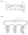
- the embodiments of the illustrated in both Figures 1 and 2 inventive devices have a between the first reactor A for the urea cleavage and the second reactor C for the introduction of ammonia in water a third reactor B for the separation of carbon dioxide from in the urea fission produced gas mixture of ammonia and carbon dioxide.
- the first reactor A has an inlet 1 for the supply of urea, water and optionally urease (urea-cleaving enzyme), the second reactor C an inlet 2 for the supply of water and an outlet 3 for the Removal of ammonia water.
- the three reactors A, B and C are open and accommodated in a closed gas space 10 such that both the aqueous receiver for collecting the ammonia (reactor C) and the receiver for absorbing the carbon dioxide (reactor B) in equilibrium with reactor A (passive gas exchange).
- a substance with high affinity for CO 2 causes the ammonia water produced in the second reactor C is largely free of CO 2 .
- the binder for carbon dioxide is, for example, a solid-state granulate (for example calcium hydroxide).
- the aqueous urea solution in the first reactor A is heated, on the one hand the urea fission is favored and on the other hand by the Temperature difference between the urea solution in the first reactor A and the Ammoniakwasservorlage in the second reactor C, a shift of Solubility equilibrium of the ammonia gas from A to C is formed.
- FIG. 2 shows an embodiment of the device according to the invention closed reactors A, B and C, wherein reactor B is a means for binding the Contains carbon dioxide.
- Reactors A and B or B and C are with Connecting lines from the gas space of the preceding into the liquid of connected downstream of the reactor in the sense of gas washing bottles. Of the Gas exchange is through the return connection 11 with pump 12 between the second and first reactor forced.
- FIG. 3 shows, again very schematically, another embodiment of the inventive device in which the means for separating the Carbon dioxide integrated into the second reactor C and / or downstream of this is, so the carbon dioxide not from the gas mixture but from the Ammonia water is separated.
- the first and second reactors A and C corresponding to those according to FIG. 2.
- the outlet 3 of the second reactor C leads into a distillation vessel D, from which the ammonia water in order Separation of a sparingly soluble, carbon dioxide-binding precipitate and for concentration in a distillate vessel E with an outlet 4 for the Ammonia water is distilled.
- the medium for binding the carbon dioxide is in the reactor C or in the distillation vessel D submitted.
- a closed gas space 1 In a closed gas space 1 according to FIG. 1, three templates were provided at room temperature: 50 ml of 10% urea solution + 10 mg of urease in the open reactor A, 10 g of Ca (OH) 2 powder laid out on the container bottom (reactor B) and 50 ml of H 2 O in the open Reactor C.
- the carbon dioxide CO 2 formed in A was absorbed by the calcium hydroxide Ca (OH) 2 and precipitated as the calcium carbonate CaCO 3 .
- the urea concentration in A was kept constant.
- washing bottles were the same templates as in Example 1 submitted, wherein the calcium hydroxide in reactor B as a powder has been.
- the washing bottles were in the manner shown in Figure 2 to a Device interconnected according to the invention.
- the gas circulation was through forced the pump 2.
- Reactor A was heated to 37 ° C, reactor C to 1 ° C cooled.
- the slightly concentrated ammonia water was heated to 60 ° C and the distillate was kept at room temperature (23 ° C). In the distillate, a final ammonia content of 16% was achieved in this way.
Landscapes
- Chemical & Material Sciences (AREA)
- Organic Chemistry (AREA)
- Engineering & Computer Science (AREA)
- Chemical Kinetics & Catalysis (AREA)
- Inorganic Chemistry (AREA)
- Analytical Chemistry (AREA)
- Health & Medical Sciences (AREA)
- Combustion & Propulsion (AREA)
- Biomedical Technology (AREA)
- Environmental & Geological Engineering (AREA)
- General Engineering & Computer Science (AREA)
- General Chemical & Material Sciences (AREA)
- Oil, Petroleum & Natural Gas (AREA)
- Mechanical Engineering (AREA)
- Toxicology (AREA)
- Life Sciences & Earth Sciences (AREA)
- Geology (AREA)
- Treating Waste Gases (AREA)
- Exhaust Gas After Treatment (AREA)
Description

- Figur 1 und 2
- zwei sehr schematisch dargestellte, beispielhafte Ausführungsformen der erfindungsgemässen Vorrichtung mit zwischen ersten und zweiten Reaktor geschaltetem Mittel zur Abtrennung des Kohlendioxids.
- Figur 3
- eine weitere, beispielhafte Ausführungsform der erfindungsgemässen Vorrichtung mit im zweiten Reaktor integriertem und/oder dem zweiten Reaktor nachgeschaltetem Mittel zur Abtrennung des Kohlendioxids.
Claims (11)
- Verfahren zur Herstellung eines Entstickungsmittels, das sich insbesondere für die Entstickung von Abgasen von Dieselmotoren eignet, wobei das Entstickungsmittel durch Harnstoffspaltung hergestelltes Ammoniak enthält, dadurch gekennzeichnet, dass das aus der Harnstoffspaltung anfallende, gasförmige Ammoniak in Wasser eingeleitet wird, und dass das ebenfalls bei der Harnstoffspaltung anfallende Kohlendioxid vom Ammoniak abgetrennt wird.
- Verfahren nach Anspruch 1, dadurch gekennzeichnet, dass das aus der Harnstoffspaltung anfallende Kohlendioxid durch Bildung einer schwerlöslichen Verbindung abgetrennt wird.
- Verfahren nach einem der Ansprüche 1 oder 2, dadurch gekennzeichnet, dass das durch Einleitung des Ammoniaks in Wasser entstehende Ammoniakwasser zusätzlich aufkonzentriert wird.
- Verfahren nach Anspruch 3, dadurch gekennzeichnet, dass die Aufkonzentrierung eine Destillation ist.
- Verfahren nach einem der Ansprüche 1 bis 4, dadurch gekennzeichnet, dass das Kohlendioxid vor der Einleitung des Ammoniaks in Wasser abgetrennt wird.
- Verfahren nach Anspruch 3 oder 4, dadurch gekennzeichnet, dass das Kohlendioxid aus dem durch Einleitung des Ammoniaks in Wasser entstehenden Ammoniakwasser ausgefällt wird.
- Verwendung des Verfahrens nach einem der Ansprüche 1 bis 6 zur Herstellung von Ammoniakwasser in einem Dieselfahrzeug oder an einer Tankstelle.
- Vorrichtung zur Herstellung eines Entstickungsmittels, das sich insbesondere für die Entstickung von Abgasen von Dieselmotoren eignet, wobei das Entstickungsmittel durch Harnstoffspaltung hergestelltes Ammoniak enthält, welche Vorrichtung einen ersten Reaktor (A) für die Harnstoffspaltung aufweist, dadurch gekennzeichnet, dass die Vorrichtung ferner einen zweiten Reaktor (C) für das Einleiten des aus der Harnstoffspaltung anfallenden Ammoniaks in Wasser und ein Mittel zur Abtrennung von Kohlendioxid vom Ammoniak aufweist.
- Vorrichtung nach Anspruch 8, dadurch gekennzeichnet, dass das Mittel zur Abtrennung des Kohlendioxids zwischen den ersten Reaktor (A) und den zweiten Reaktor (C) geschaltet ist.
- Vorrichtung nach Anspruch 8, dadurch gekennzeichnet, dass das Mittel zum Abtrennen des Kohlendioxids im zweiten Reaktor (C) integriert ist.
- Vorrichtung nach Anspruch 8, dadurch gekennzeichnet, dass das Mittel zum Abtrennen des Kohlendioxids im ersten Reaktor (A) integriert ist.
Priority Applications (3)
| Application Number | Priority Date | Filing Date | Title |
|---|---|---|---|
| DE50301189T DE50301189D1 (de) | 2003-05-12 | 2003-05-12 | Verfahren und Vorrichtung zur Herstellung eines Abgas-Entstickungsmittels |
| EP03405330A EP1479652B1 (de) | 2003-05-12 | 2003-05-12 | Verfahren und Vorrichtung zur Herstellung eines Abgas-Entstickungsmittels |
| AT03405330T ATE304512T1 (de) | 2003-05-12 | 2003-05-12 | Verfahren und vorrichtung zur herstellung eines abgas-entstickungsmittels |
Applications Claiming Priority (1)
| Application Number | Priority Date | Filing Date | Title |
|---|---|---|---|
| EP03405330A EP1479652B1 (de) | 2003-05-12 | 2003-05-12 | Verfahren und Vorrichtung zur Herstellung eines Abgas-Entstickungsmittels |
Publications (2)
| Publication Number | Publication Date |
|---|---|
| EP1479652A1 EP1479652A1 (de) | 2004-11-24 |
| EP1479652B1 true EP1479652B1 (de) | 2005-09-14 |
Family
ID=33041136
Family Applications (1)
| Application Number | Title | Priority Date | Filing Date |
|---|---|---|---|
| EP03405330A Expired - Lifetime EP1479652B1 (de) | 2003-05-12 | 2003-05-12 | Verfahren und Vorrichtung zur Herstellung eines Abgas-Entstickungsmittels |
Country Status (3)
| Country | Link |
|---|---|
| EP (1) | EP1479652B1 (de) |
| AT (1) | ATE304512T1 (de) |
| DE (1) | DE50301189D1 (de) |
Families Citing this family (1)
| Publication number | Priority date | Publication date | Assignee | Title |
|---|---|---|---|---|
| FR2953737B1 (fr) | 2009-12-11 | 2013-03-15 | Inst Francais Du Petrole | Procede de traitement de polluants contenus dans des gaz d'echappement, notamment d'un moteur a combustion interne, et installation utilisant un tel procede |
Family Cites Families (3)
| Publication number | Priority date | Publication date | Assignee | Title |
|---|---|---|---|---|
| DE4038054A1 (de) * | 1990-11-29 | 1992-06-04 | Man Technologie Gmbh | Verfahren und vorrichtung zur selektiven katalytischen no(pfeil abwaerts)x(pfeil abwaerts)-reduktion in sauerstoffhaltigen abgasen |
| US5252308A (en) * | 1991-12-31 | 1993-10-12 | Union Oil Company Of California | Transporting urea for quantitative conversion into ammonia |
| DE19960976C2 (de) * | 1999-12-17 | 2002-01-24 | Karlsruhe Forschzent | Vorrichtung zur katalysierten Reduktion von Stickoxiden im Abgas einer Verbrennungsmaschine |
-
2003
- 2003-05-12 EP EP03405330A patent/EP1479652B1/de not_active Expired - Lifetime
- 2003-05-12 AT AT03405330T patent/ATE304512T1/de not_active IP Right Cessation
- 2003-05-12 DE DE50301189T patent/DE50301189D1/de not_active Expired - Fee Related
Also Published As
| Publication number | Publication date |
|---|---|
| EP1479652A1 (de) | 2004-11-24 |
| ATE304512T1 (de) | 2005-09-15 |
| DE50301189D1 (de) | 2005-10-20 |
Similar Documents
| Publication | Publication Date | Title |
|---|---|---|
| EP0364694B1 (de) | Verfahren zur Reduktion von in Abgasen enthaltenen Stickoxiden mittels eines zeolithhaltigen Katalysators | |
| DE69821505T2 (de) | Verfahren zur herstellung von ammonium aus harnstoff und anwendung dieses verfahrens | |
| DE69532419T2 (de) | Regeneration eines katalysators/absorbers | |
| EP0981403B1 (de) | Verfahren und vorrichtung zur reduktion von stickoxiden an einem scr-katalysator | |
| DE3232543C2 (de) | Verfahren zum Entfernen von Schwefel- und Stickstoffoxiden aus einem Abgas | |
| EP3265213B1 (de) | Verfahren und vorrichtung zur dynamischen abgasbehandlung | |
| DE102011105419B4 (de) | Verfahren zur Reduktion von Stickoxiden | |
| EP2888028B1 (de) | Verfahren und vorrichtung zur behandlung von abgasen | |
| DE2236208A1 (de) | Verfahren zur rueckgewinnung von lithiumkarbonat aus waessrigen, flugasche und/oder koks enthaltenden schlammischungen | |
| DE69502712T2 (de) | Verfahren und vorrichtung zur behandlung von abwässern, die organische stoffe enthalten, insbesondere durch nassoxydation mit interner feststoffrückführung und kläranlage zur durchführung des verfahrens. | |
| EP0264041A2 (de) | Verfahren und Anlage zur Rückgewinnung von Ammoniak beim Abscheiden von Stickoxiden aus Rauchgasen | |
| DE29708591U1 (de) | Vorrichtung zum Zuführen von Ammoniak in den Abgasstrom eines Verbrennungsmotors | |
| DE2259763C3 (de) | Verfahren zur Reinigung von Stickstoffoxide enthaltenden Gasen und Vorrichtung zu dessen Durchführung | |
| DE102014217450A1 (de) | Vorrichtung zur Wassergewinnung aus einem Gas und Verfahren zur Stickoxidreduktion | |
| DE2520540B2 (de) | Verfahren zum Entfernen von Stickoxiden aus Verbrennungsabgasen | |
| DE2423828B2 (de) | Verfahren zum Reinigen von Industriegasen | |
| EP2118460A1 (de) | Verfahren und vorrichtung zur erzeugung von ammoniak für die abgasbehandlung bei brennkraftmaschinen in einem kraftfahrzeug | |
| DE2549796C3 (de) | Verfahren zur Entfernung von Chlorwasserstoff aus Abgasen | |
| DE2950710A1 (de) | Verfahren zur behandlung von abwasser | |
| EP1479652B1 (de) | Verfahren und Vorrichtung zur Herstellung eines Abgas-Entstickungsmittels | |
| DE2848788A1 (de) | Verfahren zur behandlung von stickstoff- und schwefeloxide enthaltendem abgas | |
| DE69905378T2 (de) | Verfahren zur reinigung eines abgases | |
| WO1993008121A1 (de) | VERFAHREN ZUR HERSTELLUNG VON HYDROXYLAMIN AUS NOx ENTHALTENDEN ABGASEN | |
| DE2455233A1 (de) | Verfahren zur entfernung und gewinnung von ammoniak aus abfallwasser | |
| DE2502079C3 (de) | Verfahren zum Entfernen von Schwefeldioxid aus Verbrennungsabgasen |
Legal Events
| Date | Code | Title | Description |
|---|---|---|---|
| PUAI | Public reference made under article 153(3) epc to a published international application that has entered the european phase |
Free format text: ORIGINAL CODE: 0009012 |
|
| 17P | Request for examination filed |
Effective date: 20040316 |
|
| AK | Designated contracting states |
Kind code of ref document: A1 Designated state(s): AT BE BG CH CY CZ DE DK EE ES FI FR GB GR HU IE IT LI LU MC NL PT RO SE SI SK TR |
|
| AX | Request for extension of the european patent |
Extension state: AL LT LV MK |
|
| GRAP | Despatch of communication of intention to grant a patent |
Free format text: ORIGINAL CODE: EPIDOSNIGR1 |
|
| GRAS | Grant fee paid |
Free format text: ORIGINAL CODE: EPIDOSNIGR3 |
|
| GRAA | (expected) grant |
Free format text: ORIGINAL CODE: 0009210 |
|
| AKX | Designation fees paid |
Designated state(s): AT BE BG CH CY CZ DE DK EE ES FI FR GB GR HU IE IT LI LU MC NL PT RO SE SI SK TR |
|
| AK | Designated contracting states |
Kind code of ref document: B1 Designated state(s): AT BE BG CH CY CZ DE DK EE ES FI FR GB GR HU IE IT LI LU MC NL PT RO SE SI SK TR |
|
| PG25 | Lapsed in a contracting state [announced via postgrant information from national office to epo] |
Ref country code: GB Free format text: LAPSE BECAUSE OF FAILURE TO SUBMIT A TRANSLATION OF THE DESCRIPTION OR TO PAY THE FEE WITHIN THE PRESCRIBED TIME-LIMIT Effective date: 20050914 Ref country code: IT Free format text: LAPSE BECAUSE OF FAILURE TO SUBMIT A TRANSLATION OF THE DESCRIPTION OR TO PAY THE FEE WITHIN THE PRESCRIBED TIME-LIMIT;WARNING: LAPSES OF ITALIAN PATENTS WITH EFFECTIVE DATE BEFORE 2007 MAY HAVE OCCURRED AT ANY TIME BEFORE 2007. THE CORRECT EFFECTIVE DATE MAY BE DIFFERENT FROM THE ONE RECORDED. Effective date: 20050914 Ref country code: NL Free format text: LAPSE BECAUSE OF FAILURE TO SUBMIT A TRANSLATION OF THE DESCRIPTION OR TO PAY THE FEE WITHIN THE PRESCRIBED TIME-LIMIT Effective date: 20050914 Ref country code: FI Free format text: LAPSE BECAUSE OF FAILURE TO SUBMIT A TRANSLATION OF THE DESCRIPTION OR TO PAY THE FEE WITHIN THE PRESCRIBED TIME-LIMIT Effective date: 20050914 Ref country code: CZ Free format text: LAPSE BECAUSE OF FAILURE TO SUBMIT A TRANSLATION OF THE DESCRIPTION OR TO PAY THE FEE WITHIN THE PRESCRIBED TIME-LIMIT Effective date: 20050914 Ref country code: SI Free format text: LAPSE BECAUSE OF FAILURE TO SUBMIT A TRANSLATION OF THE DESCRIPTION OR TO PAY THE FEE WITHIN THE PRESCRIBED TIME-LIMIT Effective date: 20050914 Ref country code: RO Free format text: LAPSE BECAUSE OF FAILURE TO SUBMIT A TRANSLATION OF THE DESCRIPTION OR TO PAY THE FEE WITHIN THE PRESCRIBED TIME-LIMIT Effective date: 20050914 Ref country code: SK Free format text: LAPSE BECAUSE OF FAILURE TO SUBMIT A TRANSLATION OF THE DESCRIPTION OR TO PAY THE FEE WITHIN THE PRESCRIBED TIME-LIMIT Effective date: 20050914 Ref country code: IE Free format text: LAPSE BECAUSE OF FAILURE TO SUBMIT A TRANSLATION OF THE DESCRIPTION OR TO PAY THE FEE WITHIN THE PRESCRIBED TIME-LIMIT Effective date: 20050914 |
|
| REG | Reference to a national code |
Ref country code: GB Ref legal event code: FG4D Free format text: NOT ENGLISH |
|
| REG | Reference to a national code |
Ref country code: CH Ref legal event code: EP |
|
| REG | Reference to a national code |
Ref country code: IE Ref legal event code: FG4D Free format text: LANGUAGE OF EP DOCUMENT: GERMAN |
|
| REF | Corresponds to: |
Ref document number: 50301189 Country of ref document: DE Date of ref document: 20051020 Kind code of ref document: P |
|
| PG25 | Lapsed in a contracting state [announced via postgrant information from national office to epo] |
Ref country code: GR Free format text: LAPSE BECAUSE OF FAILURE TO SUBMIT A TRANSLATION OF THE DESCRIPTION OR TO PAY THE FEE WITHIN THE PRESCRIBED TIME-LIMIT Effective date: 20051214 Ref country code: DK Free format text: LAPSE BECAUSE OF FAILURE TO SUBMIT A TRANSLATION OF THE DESCRIPTION OR TO PAY THE FEE WITHIN THE PRESCRIBED TIME-LIMIT Effective date: 20051214 Ref country code: SE Free format text: LAPSE BECAUSE OF FAILURE TO SUBMIT A TRANSLATION OF THE DESCRIPTION OR TO PAY THE FEE WITHIN THE PRESCRIBED TIME-LIMIT Effective date: 20051214 Ref country code: BG Free format text: LAPSE BECAUSE OF FAILURE TO SUBMIT A TRANSLATION OF THE DESCRIPTION OR TO PAY THE FEE WITHIN THE PRESCRIBED TIME-LIMIT Effective date: 20051214 |
|
| PG25 | Lapsed in a contracting state [announced via postgrant information from national office to epo] |
Ref country code: ES Free format text: LAPSE BECAUSE OF FAILURE TO SUBMIT A TRANSLATION OF THE DESCRIPTION OR TO PAY THE FEE WITHIN THE PRESCRIBED TIME-LIMIT Effective date: 20051225 |
|
| PG25 | Lapsed in a contracting state [announced via postgrant information from national office to epo] |
Ref country code: PT Free format text: LAPSE BECAUSE OF FAILURE TO SUBMIT A TRANSLATION OF THE DESCRIPTION OR TO PAY THE FEE WITHIN THE PRESCRIBED TIME-LIMIT Effective date: 20060214 |
|
| NLV1 | Nl: lapsed or annulled due to failure to fulfill the requirements of art. 29p and 29m of the patents act | ||
| PG25 | Lapsed in a contracting state [announced via postgrant information from national office to epo] |
Ref country code: HU Free format text: LAPSE BECAUSE OF FAILURE TO SUBMIT A TRANSLATION OF THE DESCRIPTION OR TO PAY THE FEE WITHIN THE PRESCRIBED TIME-LIMIT Effective date: 20060315 |
|
| GBV | Gb: ep patent (uk) treated as always having been void in accordance with gb section 77(7)/1977 [no translation filed] |
Effective date: 20050914 |
|
| PGFP | Annual fee paid to national office [announced via postgrant information from national office to epo] |
Ref country code: DE Payment date: 20060418 Year of fee payment: 4 |
|
| REG | Reference to a national code |
Ref country code: IE Ref legal event code: FD4D |
|
| PG25 | Lapsed in a contracting state [announced via postgrant information from national office to epo] |
Ref country code: AT Free format text: LAPSE BECAUSE OF NON-PAYMENT OF DUE FEES Effective date: 20060512 |
|
| PG25 | Lapsed in a contracting state [announced via postgrant information from national office to epo] |
Ref country code: BE Free format text: LAPSE BECAUSE OF NON-PAYMENT OF DUE FEES Effective date: 20060531 Ref country code: MC Free format text: LAPSE BECAUSE OF NON-PAYMENT OF DUE FEES Effective date: 20060531 |
|
| PLBE | No opposition filed within time limit |
Free format text: ORIGINAL CODE: 0009261 |
|
| STAA | Information on the status of an ep patent application or granted ep patent |
Free format text: STATUS: NO OPPOSITION FILED WITHIN TIME LIMIT |
|
| 26N | No opposition filed |
Effective date: 20060615 |
|
| PG25 | Lapsed in a contracting state [announced via postgrant information from national office to epo] |
Ref country code: FR Free format text: LAPSE BECAUSE OF FAILURE TO SUBMIT A TRANSLATION OF THE DESCRIPTION OR TO PAY THE FEE WITHIN THE PRESCRIBED TIME-LIMIT Effective date: 20061020 |
|
| EN | Fr: translation not filed | ||
| EN | Fr: translation not filed | ||
| BERE | Be: lapsed |
Owner name: HOCHSCHULE RAPPERSWIL, INSTITUT FUR ANGEWANDTE UM Effective date: 20060531 |
|
| PG25 | Lapsed in a contracting state [announced via postgrant information from national office to epo] |
Ref country code: DE Free format text: LAPSE BECAUSE OF NON-PAYMENT OF DUE FEES Effective date: 20071201 |
|
| PG25 | Lapsed in a contracting state [announced via postgrant information from national office to epo] |
Ref country code: EE Free format text: LAPSE BECAUSE OF FAILURE TO SUBMIT A TRANSLATION OF THE DESCRIPTION OR TO PAY THE FEE WITHIN THE PRESCRIBED TIME-LIMIT Effective date: 20050914 |
|
| PG25 | Lapsed in a contracting state [announced via postgrant information from national office to epo] |
Ref country code: TR Free format text: LAPSE BECAUSE OF FAILURE TO SUBMIT A TRANSLATION OF THE DESCRIPTION OR TO PAY THE FEE WITHIN THE PRESCRIBED TIME-LIMIT Effective date: 20050914 Ref country code: LU Free format text: LAPSE BECAUSE OF NON-PAYMENT OF DUE FEES Effective date: 20060512 |
|
| PGFP | Annual fee paid to national office [announced via postgrant information from national office to epo] |
Ref country code: CH Payment date: 20080421 Year of fee payment: 6 |
|
| PG25 | Lapsed in a contracting state [announced via postgrant information from national office to epo] |
Ref country code: FR Free format text: LAPSE BECAUSE OF FAILURE TO SUBMIT A TRANSLATION OF THE DESCRIPTION OR TO PAY THE FEE WITHIN THE PRESCRIBED TIME-LIMIT Effective date: 20050914 Ref country code: CY Free format text: LAPSE BECAUSE OF FAILURE TO SUBMIT A TRANSLATION OF THE DESCRIPTION OR TO PAY THE FEE WITHIN THE PRESCRIBED TIME-LIMIT Effective date: 20050914 |
|
| REG | Reference to a national code |
Ref country code: CH Ref legal event code: PL |
|
| PG25 | Lapsed in a contracting state [announced via postgrant information from national office to epo] |
Ref country code: CH Free format text: LAPSE BECAUSE OF NON-PAYMENT OF DUE FEES Effective date: 20090531 Ref country code: LI Free format text: LAPSE BECAUSE OF NON-PAYMENT OF DUE FEES Effective date: 20090531 |