EP1479889B1 - Moteur à turbine à gaz et entrée de moteur à turbine à gaz munis d'un dispositif pour éviter le givre - Google Patents
Moteur à turbine à gaz et entrée de moteur à turbine à gaz munis d'un dispositif pour éviter le givre Download PDFInfo
- Publication number
- EP1479889B1 EP1479889B1 EP04252567A EP04252567A EP1479889B1 EP 1479889 B1 EP1479889 B1 EP 1479889B1 EP 04252567 A EP04252567 A EP 04252567A EP 04252567 A EP04252567 A EP 04252567A EP 1479889 B1 EP1479889 B1 EP 1479889B1
- Authority
- EP
- European Patent Office
- Prior art keywords
- intake
- gas turbine
- chamber
- engine
- turbine engine
- Prior art date
- Legal status (The legal status is an assumption and is not a legal conclusion. Google has not performed a legal analysis and makes no representation as to the accuracy of the status listed.)
- Expired - Lifetime
Links
- 230000005611 electricity Effects 0.000 claims description 8
- 238000001816 cooling Methods 0.000 claims description 5
- 239000012530 fluid Substances 0.000 claims description 4
- 239000007858 starting material Substances 0.000 claims description 3
- 239000003921 oil Substances 0.000 description 9
- 239000010705 motor oil Substances 0.000 description 4
- 238000002485 combustion reaction Methods 0.000 description 3
- 230000001141 propulsive effect Effects 0.000 description 3
- 230000015572 biosynthetic process Effects 0.000 description 2
- 238000010438 heat treatment Methods 0.000 description 2
- 239000003595 mist Substances 0.000 description 2
- 238000005452 bending Methods 0.000 description 1
- 230000006835 compression Effects 0.000 description 1
- 238000007906 compression Methods 0.000 description 1
- 238000007710 freezing Methods 0.000 description 1
- 230000008014 freezing Effects 0.000 description 1
- 239000000446 fuel Substances 0.000 description 1
- 230000003116 impacting effect Effects 0.000 description 1
- 230000003993 interaction Effects 0.000 description 1
- 230000007257 malfunction Effects 0.000 description 1
- 239000000203 mixture Substances 0.000 description 1
- 230000002265 prevention Effects 0.000 description 1
- 238000011144 upstream manufacturing Methods 0.000 description 1
- XLYOFNOQVPJJNP-UHFFFAOYSA-N water Substances O XLYOFNOQVPJJNP-UHFFFAOYSA-N 0.000 description 1
Images

Classifications
-
- F—MECHANICAL ENGINEERING; LIGHTING; HEATING; WEAPONS; BLASTING
- F02—COMBUSTION ENGINES; HOT-GAS OR COMBUSTION-PRODUCT ENGINE PLANTS
- F02C—GAS-TURBINE PLANTS; AIR INTAKES FOR JET-PROPULSION PLANTS; CONTROLLING FUEL SUPPLY IN AIR-BREATHING JET-PROPULSION PLANTS
- F02C7/00—Features, components parts, details or accessories, not provided for in, or of interest apart form groups F02C1/00 - F02C6/00; Air intakes for jet-propulsion plants
- F02C7/12—Cooling of plants
-
- F—MECHANICAL ENGINEERING; LIGHTING; HEATING; WEAPONS; BLASTING
- F02—COMBUSTION ENGINES; HOT-GAS OR COMBUSTION-PRODUCT ENGINE PLANTS
- F02C—GAS-TURBINE PLANTS; AIR INTAKES FOR JET-PROPULSION PLANTS; CONTROLLING FUEL SUPPLY IN AIR-BREATHING JET-PROPULSION PLANTS
- F02C7/00—Features, components parts, details or accessories, not provided for in, or of interest apart form groups F02C1/00 - F02C6/00; Air intakes for jet-propulsion plants
- F02C7/04—Air intakes for gas-turbine plants or jet-propulsion plants
- F02C7/047—Heating to prevent icing
-
- F—MECHANICAL ENGINEERING; LIGHTING; HEATING; WEAPONS; BLASTING
- F02—COMBUSTION ENGINES; HOT-GAS OR COMBUSTION-PRODUCT ENGINE PLANTS
- F02C—GAS-TURBINE PLANTS; AIR INTAKES FOR JET-PROPULSION PLANTS; CONTROLLING FUEL SUPPLY IN AIR-BREATHING JET-PROPULSION PLANTS
- F02C7/00—Features, components parts, details or accessories, not provided for in, or of interest apart form groups F02C1/00 - F02C6/00; Air intakes for jet-propulsion plants
- F02C7/32—Arrangement, mounting, or driving, of auxiliaries
-
- Y—GENERAL TAGGING OF NEW TECHNOLOGICAL DEVELOPMENTS; GENERAL TAGGING OF CROSS-SECTIONAL TECHNOLOGIES SPANNING OVER SEVERAL SECTIONS OF THE IPC; TECHNICAL SUBJECTS COVERED BY FORMER USPC CROSS-REFERENCE ART COLLECTIONS [XRACs] AND DIGESTS
- Y02—TECHNOLOGIES OR APPLICATIONS FOR MITIGATION OR ADAPTATION AGAINST CLIMATE CHANGE
- Y02T—CLIMATE CHANGE MITIGATION TECHNOLOGIES RELATED TO TRANSPORTATION
- Y02T50/00—Aeronautics or air transport
- Y02T50/60—Efficient propulsion technologies, e.g. for aircraft
Definitions
- the present invention relates to an intake of an aeroengine nacelle and in particular to providing a heated intake for prevention of ice build up thereon.
- the leading edge of the intake of aeroengines is particularly prone to icing during flight through clouds containing super-cooled water droplets or ground operation in freezing fog. Protection against ice formation may be required since icing of the intake may significantly affect the airflow through the engine, causing a loss of performance and possible malfunction of the engine. In addition, damage may result from ice breaking away and being ingested into the engine or impacting acoustic liners around the intake duct.
- GB2136880 relates to a turbo-prop engine where heat from a reduction gearbox is transferred by conduction through the engine casing to the intake lip.
- An annular air intake comprises a number of stator vanes having heat pipes therethrough connecting the interior of the reduction gearbox with a heat sink situated adjacent the upstream lip of the intake. Heat from the hot oil mist within the gearbox is thus conducted to the heat sink and serves to heat up the intake lip to prevent the formation of ice thereon, while at the same time the oil mist is cooled.
- failure of the system is likely to compromise engine operability.
- a further problem is that the heat sink and piping imposes a significant weight penalty to the engine and nacelle assembly.
- GB2204361 discloses the transfer of hot oil from a reduction gearbox to a heat exchanger and with an air scoop that directs external air through the heat exchanger and then the warmed air is used to de-ice the intake.
- a serious disadvantage with this arrangement is that the air scoop causes additional aerodynamic drag, therefore reducing the overall efficiency of the engine.
- GB626,571 recites a heat exchanger wrapped around an outer wall of an annular flow passage, adjacent an air inlet of a gas turbine engine.
- the heat exchanger is connected in flow relation to a grille, which is arranged across the flow passage. Both the grille and heat exchanger proportionally receive heated oil to maintain the grille at a temperature high enough to prevent icing.
- an object of the present invention to provide an anti-icing system for at least the intake of a gas turbine engine that does not cause an aerodynamic drag, does not use engine oil or air bled from a compressor and is a closed system.
- a gas turbine engine comprising a nacelle having an intake, the intake defining a generally annular chamber, an engine accessory and a heat exchanger for cooling a fluid of the accessory the heat exchanger is disposed within the chamber operable to provide heat to prevent ice forming on the intake during engine operation characterised in that the chamber is closed and a means for circulating air around the chamber and driving the air through the heat exchanger is provided within the chamber.
- the means for circulating air comprising at least one electrically driven fan.
- the accessory is a generator operable to generate electricity during engine operation.
- the accessory is a starter/generator operable to drive the engine at start up and generate electricity during engine operation.
- the accessory is a gearbox for transferring drive between an engine shaft and the accessory.
- a second heat exchanger is included in the chamber and associated to a second accessory.
- the intake comprises at least one rib extending substantially around the circumference of and into the chamber.
- the at least one rib increases in extent into the chamber generally from the heat exchanger thereby increasing its surface area for heat exchanging to provide a more constant heat exchange around the circumference of the intake.
- further ribs are provided around the circumference to increase the surface area for heat exchanging around the intake to provide a more constant heat exchange around the circumference of the intake.
- the ribs also provide increased rigidity of the intake to protect against foreign body impacts.
- an intake for a gas turbine engine defining a generally annular chamber and capable of housing an engine accessory and a heat exchanger capable of cooling a fluid of the accessory, the heat exchanger is operable to provide heat to the intake characterised in that the chamber is closed and a means for circulating air around the chamber and driving the air through the heat exchanger is provided within the chamber.
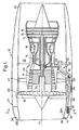
- a ducted fan gas turbine engine generally indicated at 10 has a principal and rotational axis 11.
- the engine 10 comprises, in axial flow series, an air intake 12, a propulsive fan 13, an intermediate pressure compressor 14, a high-pressure compressor 15, combustion equipment 16, a high-pressure turbine 17, and intermediate pressure turbine 18, a low-pressure turbine 19 and an exhaust nozzle 20.
- a nacelle 21 generally surrounds the engine 10 and defines both the intake 12 and the exhaust nozzle 20.
- the gas turbine engine 10 works in the conventional manner so that air entering the intake 11 is accelerated by the fan 13 to produce two air flows: a first air flow into the intermediate pressure compressor 14 and a second air flow which passes through a bypass duct 22 to provide propulsive thrust.
- the intermediate pressure compressor 14 compresses the air flow directed into it before delivering that air to the high pressure compressor 15 where further compression takes place.
- the compressed air exhausted from the high-pressure compressor 15 is directed into the combustion equipment 16 where it is mixed with fuel and the mixture combusted.
- the resultant hot combustion products then expand through, and thereby drive the high, intermediate and low-pressure turbines 17, 18, 19 before being exhausted through the nozzle 20 to provide additional propulsive thrust.
- the high, intermediate and low-pressure turbines 17, 18, 19 respectively drive the high and intermediate pressure compressors 15, 14 and the fan 13 by suitable interconnecting shafts 23, 24, 25.
- the fan 13 is circumferentially surrounded by a structural member in the form of a fan casing 26, which is supported by an annular array of outlet guide vanes 27.
- the engine 10 further comprises a gearbox/generator assembly 28 used for engine start up and for generating electricity once the engine has been started and working in convention fashion.
- the generated electricity is used for engine and associated aircraft electrical accessories as well known in the art.
- the gearbox/generator assembly 28 is drivingly connected to the high-pressure shaft 24, however, in other embodiments may be driven by any one or more of the shafts 24, 25.
- the gearbox/generator assembly 28 comprises an internal gearbox 29 connecting a first drive shaft 30 to the high-pressure shaft 23, an intermediate gearbox 31 connecting the first drive shaft 30 to a second drive shaft 32 and an external gearbox 33 drivingly connected to the second drive shaft 32.
- the external gearbox 33 is drivingly connected to a generator 34 that is capable of the aforesaid engine operation.
- the generator 34 and external gearbox 33 are housed within the nacelle 21.
- the first drive shaft 30, intermediate gearbox 31 and the second drive shaft 32 are housed within a bypass duct splitter fairing 40.
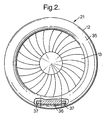
- the nacelle 21 comprises the intake 12 at its forward end; the intake 12 defines a generally D-shaped and generally annular chamber 35.
- An oil heat exchanger 36 which serves to cool the oil used in the generator 34 and gearbox 33, is located in the chamber 35.
- a pipe 39 fluidly connects the heat exchanger 36 to the generator 34. It should be appreciated by those skilled in the art, that any suitable heat exchanger 36 is usable.
- the present invention relates to the positioning of the heat exchanger 36 in the D-shaped chamber 35 and that the chamber 35 is closed. The air inside the chamber 35 is circulated, removing heat from the oil in the heat exchanger 36 and distributing the heat around the chamber 35 to heat the intake 12 and thereby prevent ice-build up on the intake 12.
- a means for circulating air 37 and driving the air through the heat exchanger 36 is provided in the form of an electrically driven fan 37, however, more than one fan 37 may be provided in the chamber 35.
- Other means for driving the fan 37 may be employed, such as, using pressurised oil or air.
- the present invention is particularly advantageous in that the heat exchanger 36 is located within the intake 12 meaning no additional pipe work or ducting is required for transferring heated air to the intake 12.
- a second advantage is present in that the arrangement is a closed system i.e. there is no external air scoop to feed air into the heat exchanger and therefore no aero drag penalty. Furthermore the chamber 35 circulating air is not vented overboard that would otherwise cause an aerodynamic drag penalty.
- the generator oil is used as the heat source as opposed to engine oil. Hence impact and subsequent damage from a foreign object, such as a bird, would not be critical to continued engine 10 operation.
- the present invention provides an anti-icing system that is always active so there is no requirement for pilot interaction or electronic control.
- the inner surface of the intake 12 comprises a means for heat exchange 38 between the air circulating within the chamber 35 and the walls of the intake 12.
- the means for heat exchange 38 comprises a plurality of generally annular extending ribs 38 that also extend from the inner walls of the intake 12 into the chamber 35.
- the ribs 38 may take many different forms to provide heat exchange and as such all provide the essential function of transferring heat from the circulating air to the intake 12 to prevent ice build up and to provide a relatively cool air supply to the heat exchanger 36.
- each rib 38A increases in height and thus surface area to accommodate and increase heat transfer of the reduction in air temperature around the intake 12 from the outlet of the heat exchanger to its inlet.
- the inclusion of ribs 38 further enhances the strength of the intake 12 and reduces the damage caused by a foreign object striking the intake 12.
- the present invention provides further advantages over the prior art in that the prior art engine comprises a thermal anti-ice pipe and outlet duct that are omitted in the arrangement of the present invention thereby giving an improved weight saving and improved arrangement of the engine's remaining piping and other accessories.
- Prior art systems supply hot engine core air to a D-shaped chamber at the front of the intakes via a large pressurised duct. In the event of duct rupture the nacelle fan cowl doors are protected from failure either by a pressure relief door or a double walled pressurised pipe.
- the present invention eliminates the requirement for these additional features.
- the space taken up by conventional cooler scoops in the rear fancase can provide additional acoustic lining. This also provides a performance advantage since bypass air not lost overboard and core air not lost for anti ice purposes.
- the accessory (33, 34) is a starter/generator (36) that is operable to drive the engine (10) at start up and generate electricity during engine (10) operation.
- FIGS 3 and 4 show the heat exchanger 36 and the fans 37 further rearward in the chamber 35. This is a preferable configuration where the heat exchanger 36 is significantly heavy and is required to be moved rearward to reduce the bending moment about the outlet guide vanes 27. As can be seen, the chamber 35 is curved axially and locally to meet and supply cooling air through the heat exchanger 36.
Landscapes
- Engineering & Computer Science (AREA)
- Chemical & Material Sciences (AREA)
- Combustion & Propulsion (AREA)
- Mechanical Engineering (AREA)
- General Engineering & Computer Science (AREA)
- Turbine Rotor Nozzle Sealing (AREA)
- Structures Of Non-Positive Displacement Pumps (AREA)
Claims (11)
- Moteur à turbine à gaz (10) comprenant une nacelle (21) ayant une admission (12), l'admission (12) définissant une chambre généralement annulaire (35), un accessoire de moteur (33, 34) et un échangeur thermique (36) pour refroidir un fluide de l'accessoire (33, 34), l'échangeur thermique (36) est disposé à l'intérieur de la chambre (35) opérante pour fournir de la chaleur pour empêcher la formation de glace sur l'admission (12) lors du fonctionnement du moteur (10), caractérisé en ce que la chambre (35) est fermée et des moyens pour faire circuler l'air (37) autour de la chambre (35) et entraîner l'air à travers l'échangeur thermique (36) sont prévus à l'intérieur de la chambre (35).
- Moteur à turbine à gaz (10) selon la revendication 1, dans lequel les moyens pour faire circuler l'air (37) comprennent au moins une soufflante entraînée électriquement (37).
- Moteur à turbine à gaz (10) selon la revendication 1 ou 2, dans lequel l'accessoire (33, 34) est un générateur (36) opérant pour générer de l'électricité lors d'un fonctionnement du moteur (10).
- Moteur à turbine à gaz (10) selon la revendication 1 ou 2, dans lequel l'accessoire (33, 34) est un démarreur/générateur (36) opérant pour entraîner le moteur (10) au démarrage et générer de l'électricité lors d'un fonctionnement du moteur (10).
- Moteur à turbine à gaz (10) selon la revendication 1 ou 2, dans lequel l'accessoire (33, 34) est une boite de transmission (34) pour transférer l'entraînement entre un arbre de moteur (23, 24, 25) et l'accessoire (33, 34).
- Moteur à turbine à gaz (10) selon l'une quelconque des revendications 3 à 5, dans lequel un second échangeur thermique (36) est inclus dans la chambre (35) et est associé à un second accessoire (33, 34).
- Moteur à turbine à gaz (10) selon l'une quelconque des revendications 1 à 6, dans lequel l'admission (12) comprend au moins une nervure (38, 38A) s'étendant sensiblement autour de la circonférence de et dans la chambre (35).
- Moteur à turbine à gaz (10) selon la revendication 7, dans lequel la au moins une nervure (38, 38A) augmente en étendue dans la chambre (35) généralement à partir de l'échangeur thermique (36) augmentant ainsi sa section pour échanger de la chaleur pour fournir un échange thermique plus constant autour de la circonférence de l'admission (12).
- Moteur à turbine à gaz (10) selon la revendication 7 ou 8, dans lequel des nervures supplémentaires (38) sont prévues autour de la circonférence pour augmenter la section pour échanger de la chaleur autour de l'admission (12) pour fournir un échange thermique plus constant autour de la circonférence de l'admission (12).
- Moteur à turbine à gaz (10) selon l'une quelconque des revendications 7 à 9, dans lequel les nervures (38) sont prévues pour augmenter la rigidité de l'admission (12) pour résister aux impacts de corps étrangers.
- Admission (12) pour un moteur à turbine à gaz (10), l'admission (12) définissant une chambre généralement annulaire (35) et capable de loger un accessoire de moteur (33, 34) et un échangeur thermique (36) capable de refroidir un fluide de l'accessoire (33, 34), l'échangeur thermique (36) est opérant pour fournir de la chaleur à l'admission (12), caractérisée en ce que la chambre (35) est fermée et des moyens pour faire circuler l'air (37) autour de la chambre (35) et pour entraîner l'air à travers l'échangeur thermique (36) sont prévus à l'intérieur de la chambre (35).
Applications Claiming Priority (2)
| Application Number | Priority Date | Filing Date | Title |
|---|---|---|---|
| GB0311663 | 2003-05-21 | ||
| GBGB0311663.9A GB0311663D0 (en) | 2003-05-21 | 2003-05-21 | Aeroengine intake |
Publications (3)
| Publication Number | Publication Date |
|---|---|
| EP1479889A2 EP1479889A2 (fr) | 2004-11-24 |
| EP1479889A3 EP1479889A3 (fr) | 2005-02-09 |
| EP1479889B1 true EP1479889B1 (fr) | 2006-05-17 |
Family
ID=9958486
Family Applications (1)
| Application Number | Title | Priority Date | Filing Date |
|---|---|---|---|
| EP04252567A Expired - Lifetime EP1479889B1 (fr) | 2003-05-21 | 2004-04-30 | Moteur à turbine à gaz et entrée de moteur à turbine à gaz munis d'un dispositif pour éviter le givre |
Country Status (4)
| Country | Link |
|---|---|
| US (1) | US7398641B2 (fr) |
| EP (1) | EP1479889B1 (fr) |
| DE (1) | DE602004000889T2 (fr) |
| GB (1) | GB0311663D0 (fr) |
Cited By (1)
| Publication number | Priority date | Publication date | Assignee | Title |
|---|---|---|---|---|
| EP4385899A1 (fr) * | 2022-12-13 | 2024-06-19 | Pratt & Whitney Canada Corp. | Système d'antigivrage thermique d'aéronef |
Families Citing this family (95)
| Publication number | Priority date | Publication date | Assignee | Title |
|---|---|---|---|---|
| US7941993B2 (en) * | 2003-10-14 | 2011-05-17 | Rolls-Royce Plc | Engine cooling |
| GB0323993D0 (en) * | 2003-10-14 | 2003-11-19 | Rolls Royce Plc | Engine cooling |
| DE102004004945A1 (de) * | 2004-01-31 | 2005-08-18 | Mtu Aero Engines Gmbh | Gasturbine, insbesondere Flugtriebwerk |
| US7055330B2 (en) * | 2004-02-25 | 2006-06-06 | United Technologies Corp | Apparatus for driving an accessory gearbox in a gas turbine engine |
| US20050183540A1 (en) * | 2004-02-25 | 2005-08-25 | Miller Guy W. | Apparatus for driving an accessory gearbox in a gas turbine engine |
| US7373771B2 (en) * | 2004-07-09 | 2008-05-20 | Pratt & Whitney Canada Corp. | Cooling arrangement for an accessory gearbox and method of cooling |
| US7500365B2 (en) * | 2005-05-05 | 2009-03-10 | United Technologies Corporation | Accessory gearbox |
| US20080016880A1 (en) * | 2006-07-24 | 2008-01-24 | Vittorio Bruno | Gas turbine starter gear shaft and method of manufacture |
| US8613591B2 (en) | 2006-09-07 | 2013-12-24 | Pratt & Whitney Canada Corp. | Fan case abradable drainage trench and slot |
| US8387362B2 (en) * | 2006-10-19 | 2013-03-05 | Michael Ralph Storage | Method and apparatus for operating gas turbine engine heat exchangers |
| US7874137B2 (en) * | 2007-06-18 | 2011-01-25 | Honeywell International Inc. | Gas turbine engine anti-ice formation device and system |
| US8312728B2 (en) | 2007-06-28 | 2012-11-20 | United Technologies Corporation | Generator with separate oil system for improved nacelle performance |
| US9091214B2 (en) * | 2007-06-28 | 2015-07-28 | United Technologies Corporation | Reduced gearbox size by separate electrically powered engine oil system |
| US8438859B2 (en) * | 2008-01-08 | 2013-05-14 | Rolls-Royce North American Technologies, Inc. | Integrated bypass engine structure |
| US8769924B2 (en) * | 2008-05-30 | 2014-07-08 | United Technologies Corporation | Gas turbine engine assembly including accessory components within the nacelle |
| US8123460B2 (en) | 2008-07-23 | 2012-02-28 | Honeywell International Inc. | UAV pod cooling using integrated duct wall heat transfer |
| US9816441B2 (en) * | 2009-03-30 | 2017-11-14 | United Technologies Corporation | Gas turbine engine with stacked accessory components |
| US8294316B2 (en) * | 2009-07-28 | 2012-10-23 | Rolls-Royce North American Technologies, Inc. | Electrical power generation apparatus for contra-rotating open-rotor aircraft propulsion system |
| FR2957585B1 (fr) * | 2010-03-17 | 2012-03-02 | Airbus Operations Sas | Procede et dispositif d'entrainement d'au moins une roue de train d'atterrissage d'un aeronef par un moteur de roue |
| FR2958974B1 (fr) * | 2010-04-16 | 2016-06-10 | Snecma | Moteur de turbine a gaz muni d'un echangeur de chaleur air-huile dans sa manche d'entree d'air |
| GB201007063D0 (en) * | 2010-04-28 | 2010-06-09 | Rolls Royce Plc | A gas turbine engine |
| US8347637B2 (en) | 2010-05-25 | 2013-01-08 | United Technologies Corporation | Accessory gearbox with internal layshaft |
| US9114877B2 (en) * | 2010-08-30 | 2015-08-25 | Ge Aviation Systems, Llc | Method and system for vehicle thermal management |
| US8490410B2 (en) | 2010-11-17 | 2013-07-23 | United Technologies Corporation | Axial accessory gearbox |
| US8490411B2 (en) | 2010-11-17 | 2013-07-23 | United Technologies Corporation | Axial accessory gearbox |
| EP2472067B1 (fr) * | 2010-12-31 | 2013-09-25 | Techspace Aero S.A. | Intégration d'un échangeur de chaleur surfacique avec débit d'air régulé dans un moteur d'avion |
| US8777793B2 (en) | 2011-04-27 | 2014-07-15 | United Technologies Corporation | Fan drive planetary gear system integrated carrier and torque frame |
| US9109464B2 (en) * | 2011-08-31 | 2015-08-18 | United Technologies Corporation | Distributed lubrication system |
| US10400629B2 (en) | 2012-01-31 | 2019-09-03 | United Technologies Corporation | Gas turbine engine shaft bearing configuration |
| US8863491B2 (en) | 2012-01-31 | 2014-10-21 | United Technologies Corporation | Gas turbine engine shaft bearing configuration |
| US9038366B2 (en) | 2012-01-31 | 2015-05-26 | United Technologies Corporation | LPC flowpath shape with gas turbine engine shaft bearing configuration |
| FR2987602B1 (fr) | 2012-03-02 | 2014-02-28 | Aircelle Sa | Nacelle de turbomoteur equipe d'un echangeur de chaleur |
| US9272777B2 (en) * | 2012-10-26 | 2016-03-01 | Textron Innovations Inc. | Helicopter gearbox auxiliary cooling system |
| EP2961962B1 (fr) | 2013-02-28 | 2019-12-25 | United Technologies Corporation | Turbine à gaz comprenant un réducteur et procédé de gestion thermique |
| FR3002978B1 (fr) | 2013-03-07 | 2016-12-30 | Aircelle Sa | Nacelle equipee d’un circuit de refroidissement d’huile a echangeur intermediaire |
| US10280794B2 (en) * | 2013-03-15 | 2019-05-07 | United Technologies Corporation | Compartment shielding |
| FR3007738B1 (fr) | 2013-06-28 | 2015-07-31 | Aircelle Sa | Dispositif de degivrage et de conditionnement pour aeronef |
| EP3094845B1 (fr) * | 2014-01-15 | 2020-04-29 | United Technologies Corporation | Systèmes de refroidissement pour moteurs à turbine à gaz |
| EP3194791B1 (fr) * | 2014-07-31 | 2020-01-08 | Sikorsky Aircraft Corporation | Ensemble de refroidissement d'huile de boîte de vitesses |
| FR3027287B1 (fr) * | 2014-10-16 | 2018-01-12 | Technofan | Equipement d'un compartiment moteur d'un aeronef, moteur, compartiment moteur et aeronef associes |
| EP3018304B1 (fr) | 2014-11-06 | 2020-10-14 | United Technologies Corporation | Système de gestion thermique pour moteur à turbine à gaz |
| US10196930B2 (en) * | 2014-12-18 | 2019-02-05 | United Technologies Corporation | System and method for controlling an environmental condition of an engine electronic component |
| US10809016B2 (en) | 2015-02-06 | 2020-10-20 | Raytheon Technologies Corporation | Heat exchanger system with additively manufactured heat transfer tube that follows a non-linear path |
| US10830543B2 (en) | 2015-02-06 | 2020-11-10 | Raytheon Technologies Corporation | Additively manufactured ducted heat exchanger system with additively manufactured header |
| US10907500B2 (en) | 2015-02-06 | 2021-02-02 | Raytheon Technologies Corporation | Heat exchanger system with spatially varied additively manufactured heat transfer surfaces |
| US10823066B2 (en) | 2015-12-09 | 2020-11-03 | General Electric Company | Thermal management system |
| US10526913B2 (en) * | 2016-04-04 | 2020-01-07 | United Technologies Corporation | Anti-windmilling system for a gas turbine engine |
| US10308366B2 (en) * | 2016-08-22 | 2019-06-04 | General Electric Company | Embedded electric machine |
| US10634060B2 (en) * | 2016-11-20 | 2020-04-28 | Mra Systems, Llc | Engine door with burst seal |
| CN107100738A (zh) * | 2016-12-19 | 2017-08-29 | 浙江科技学院 | 一种蜗扇发动机的防结冰装置 |
| US20180229850A1 (en) * | 2017-02-15 | 2018-08-16 | Pratt & Whitney Canada Corp. | Anti-icing system for gas turbine engine |
| US10823511B2 (en) | 2017-06-26 | 2020-11-03 | Raytheon Technologies Corporation | Manufacturing a heat exchanger using a material buildup process |
| FR3072421B1 (fr) * | 2017-10-18 | 2019-09-27 | Airbus Operations | Levre d'entree d'air d'un moteur d'aeronef comportant un systeme de degivrage |
| US11187156B2 (en) | 2017-11-21 | 2021-11-30 | General Electric Company | Thermal management system |
| US11125165B2 (en) | 2017-11-21 | 2021-09-21 | General Electric Company | Thermal management system |
| US11022037B2 (en) | 2018-01-04 | 2021-06-01 | General Electric Company | Gas turbine engine thermal management system |
| US11053848B2 (en) | 2018-01-24 | 2021-07-06 | General Electric Company | Additively manufactured booster splitter with integral heating passageways |
| US10941706B2 (en) | 2018-02-13 | 2021-03-09 | General Electric Company | Closed cycle heat engine for a gas turbine engine |
| US11143104B2 (en) | 2018-02-20 | 2021-10-12 | General Electric Company | Thermal management system |
| US11174789B2 (en) | 2018-05-23 | 2021-11-16 | General Electric Company | Air cycle assembly for a gas turbine engine assembly |
| US11156128B2 (en) | 2018-08-22 | 2021-10-26 | General Electric Company | Embedded electric machine |
| US11319085B2 (en) | 2018-11-02 | 2022-05-03 | General Electric Company | Fuel oxygen conversion unit with valve control |
| US11161622B2 (en) | 2018-11-02 | 2021-11-02 | General Electric Company | Fuel oxygen reduction unit |
| US11577852B2 (en) | 2018-11-02 | 2023-02-14 | General Electric Company | Fuel oxygen conversion unit |
| US11148824B2 (en) | 2018-11-02 | 2021-10-19 | General Electric Company | Fuel delivery system having a fuel oxygen reduction unit |
| US11420763B2 (en) | 2018-11-02 | 2022-08-23 | General Electric Company | Fuel delivery system having a fuel oxygen reduction unit |
| US11447263B2 (en) | 2018-11-02 | 2022-09-20 | General Electric Company | Fuel oxygen reduction unit control system |
| US11851204B2 (en) | 2018-11-02 | 2023-12-26 | General Electric Company | Fuel oxygen conversion unit with a dual separator pump |
| US11085636B2 (en) | 2018-11-02 | 2021-08-10 | General Electric Company | Fuel oxygen conversion unit |
| US11186382B2 (en) | 2018-11-02 | 2021-11-30 | General Electric Company | Fuel oxygen conversion unit |
| US11193671B2 (en) | 2018-11-02 | 2021-12-07 | General Electric Company | Fuel oxygen conversion unit with a fuel gas separator |
| US11131256B2 (en) | 2018-11-02 | 2021-09-28 | General Electric Company | Fuel oxygen conversion unit with a fuel/gas separator |
| US11391211B2 (en) | 2018-11-28 | 2022-07-19 | General Electric Company | Waste heat recovery system |
| US11015534B2 (en) | 2018-11-28 | 2021-05-25 | General Electric Company | Thermal management system |
| US10914274B1 (en) | 2019-09-11 | 2021-02-09 | General Electric Company | Fuel oxygen reduction unit with plasma reactor |
| US11774427B2 (en) | 2019-11-27 | 2023-10-03 | General Electric Company | Methods and apparatus for monitoring health of fuel oxygen conversion unit |
| US11773776B2 (en) | 2020-05-01 | 2023-10-03 | General Electric Company | Fuel oxygen reduction unit for prescribed operating conditions |
| US11866182B2 (en) | 2020-05-01 | 2024-01-09 | General Electric Company | Fuel delivery system having a fuel oxygen reduction unit |
| US11906163B2 (en) | 2020-05-01 | 2024-02-20 | General Electric Company | Fuel oxygen conversion unit with integrated water removal |
| GB2599686A (en) * | 2020-10-09 | 2022-04-13 | Rolls Royce Plc | An improved turbofan gas turbine engine |
| US11788469B2 (en) * | 2020-11-16 | 2023-10-17 | General Electric Company | Thermal management system for a gas turbine engine |
| US20220213802A1 (en) | 2021-01-06 | 2022-07-07 | General Electric Company | System for controlling blade clearances within a gas turbine engine |
| US11434824B2 (en) | 2021-02-03 | 2022-09-06 | General Electric Company | Fuel heater and energy conversion system |
| US11591965B2 (en) | 2021-03-29 | 2023-02-28 | General Electric Company | Thermal management system for transferring heat between fluids |
| US12139270B2 (en) | 2021-04-19 | 2024-11-12 | General Electric Company | Aircraft thermal transport system and method |
| US12115470B2 (en) | 2021-04-27 | 2024-10-15 | General Electric Company | Fuel oxygen reduction unit |
| US12005377B2 (en) | 2021-06-15 | 2024-06-11 | General Electric Company | Fuel oxygen reduction unit with level control device |
| US12149154B2 (en) | 2021-07-22 | 2024-11-19 | General Electric Company | Electric machine having a hybrid insulative-conductive manifold |
| US11674396B2 (en) | 2021-07-30 | 2023-06-13 | General Electric Company | Cooling air delivery assembly |
| US11920500B2 (en) | 2021-08-30 | 2024-03-05 | General Electric Company | Passive flow modulation device |
| US11542870B1 (en) | 2021-11-24 | 2023-01-03 | General Electric Company | Gas supply system |
| US11692448B1 (en) | 2022-03-04 | 2023-07-04 | General Electric Company | Passive valve assembly for a nozzle of a gas turbine engine |
| US11834992B2 (en) | 2022-04-27 | 2023-12-05 | General Electric Company | Heat exchanger capacity for one or more heat exchangers associated with an accessory gearbox of a turbofan engine |
| US12291997B1 (en) | 2024-04-30 | 2025-05-06 | General Electric Company | Variable area turbine nozzle assembly |
| US12535036B2 (en) * | 2024-07-08 | 2026-01-27 | Rtx Corporation | Engine-integrated heat exchanger |
Family Cites Families (13)
| Publication number | Priority date | Publication date | Assignee | Title |
|---|---|---|---|---|
| US2400392A (en) * | 1943-04-10 | 1946-05-14 | Westinghouse Electric Corp | Turbine apparatus |
| US2435990A (en) | 1945-08-17 | 1948-02-17 | Westinghouse Electric Corp | Gas turbine lubricating oil cooling and air inlet deicing system |
| GB626571A (en) * | 1945-08-17 | 1949-07-18 | Westinghouse Electric Int Co | Improvements in or relating to gas turbine power plants |
| US2594118A (en) | 1949-04-07 | 1952-04-22 | A V Roe Canada Ltd | Heated intake component for gas turbine engines |
| US2712727A (en) * | 1950-05-17 | 1955-07-12 | Rolls Royce | Gas turbine power plants with means for preventing or removing ice formation |
| GB1018538A (en) * | 1964-07-06 | 1966-01-26 | Rolls Royce | Gas turbine engine |
| US3981466A (en) * | 1974-12-23 | 1976-09-21 | The Boeing Company | Integrated thermal anti-icing and environmental control system |
| GB2136880A (en) | 1983-03-18 | 1984-09-26 | Rolls Royce | Anti-icing of gas turbine engine air intakes |
| US4688394A (en) * | 1985-03-14 | 1987-08-25 | Technology Un, Ltd. | Automotive heater and air conditioner and process therefor |
| US4688745A (en) | 1986-01-24 | 1987-08-25 | Rohr Industries, Inc. | Swirl anti-ice system |
| GB2194592B (en) * | 1986-08-27 | 1990-07-04 | Rolls Royce Plc | Fluid outlet duct |
| US4782658A (en) | 1987-05-07 | 1988-11-08 | Rolls-Royce Plc | Deicing of a geared gas turbine engine |
| FR2771776B1 (fr) | 1997-12-02 | 2000-01-28 | Aerospatiale | Dispositif d'evacuation d'air chaud pour capot d'entree d'air de moteur a reaction, a circuit de degivrage |
-
2003
- 2003-05-21 GB GBGB0311663.9A patent/GB0311663D0/en not_active Ceased
-
2004
- 2004-04-30 DE DE602004000889T patent/DE602004000889T2/de not_active Expired - Lifetime
- 2004-04-30 EP EP04252567A patent/EP1479889B1/fr not_active Expired - Lifetime
- 2004-05-04 US US10/837,715 patent/US7398641B2/en not_active Expired - Fee Related
Cited By (1)
| Publication number | Priority date | Publication date | Assignee | Title |
|---|---|---|---|---|
| EP4385899A1 (fr) * | 2022-12-13 | 2024-06-19 | Pratt & Whitney Canada Corp. | Système d'antigivrage thermique d'aéronef |
Also Published As
| Publication number | Publication date |
|---|---|
| GB0311663D0 (en) | 2003-06-25 |
| US20050150204A1 (en) | 2005-07-14 |
| DE602004000889D1 (de) | 2006-06-22 |
| DE602004000889T2 (de) | 2006-09-14 |
| EP1479889A2 (fr) | 2004-11-24 |
| EP1479889A3 (fr) | 2005-02-09 |
| US7398641B2 (en) | 2008-07-15 |
Similar Documents
| Publication | Publication Date | Title |
|---|---|---|
| US7398641B2 (en) | Aeroengine intake having a heat exchanger within an annular closed chamber | |
| US8876465B2 (en) | Gas turbine engine | |
| EP2990335B1 (fr) | Moteur à turbine à gaz | |
| EP4368817B1 (fr) | Système de refroidissement pour câbles d'alimentation dans un moteur à turbine à gaz | |
| EP3483414B1 (fr) | Moteur à turbine à gaz doté d'un échangeur de chaleur air-huile | |
| JP6496704B2 (ja) | 熱管理システム | |
| US20050050877A1 (en) | Methods and apparatus for operating gas turbine engines | |
| CN1924320B (zh) | 用于操作燃气涡轮发动机的方法及设备 | |
| US5363641A (en) | Integrated auxiliary power system | |
| US5114103A (en) | Aircraft engine electrically powered boundary layer bleed system | |
| US9422063B2 (en) | Cooled cooling air system for a gas turbine | |
| CN103906910B (zh) | 具有可变总压力比的燃气涡轮发动机 | |
| US8438829B2 (en) | Turboprop propulsion unit with pusher propeller | |
| US20170335769A1 (en) | Cooling device for a turbomachine supplied by a discharge circuit | |
| CA3020276A1 (fr) | Gestion de chaleur integree de propulsion hybride | |
| CN109415979A (zh) | 用于通过主动冷却的回放减轻的方法和系统 | |
| EP2514947B1 (fr) | Moteur à turbine à gaz avec ensemble formant nacelle comprenant une cavité et une structure de confinement de soufflante d'avion | |
| WO2005005810A1 (fr) | Disposition de moteur d'aeronef | |
| EP1988259A2 (fr) | Anneau de guidage de turbine avec dispositif de dégivrage | |
| WO2014143282A1 (fr) | Échangeurs de chaleur air-huile à perte minimale de pression du flux secondaire | |
| US20170137137A1 (en) | Aircraft with a propulsion unit comprising a fan at the rear of the fuselage | |
| CN117823282A (zh) | 热管理系统 | |
| US8701385B2 (en) | Method and apparatus for the operation of a turboprop aircraft engine provided with pusher propellers | |
| EP3828078B1 (fr) | Moteur à turbine à gaz, sa nacelle et procédé associé pour le fonctionnement d'un moteur de turbine à gaz | |
| CN114508426B (zh) | 用于燃气涡轮发动机的热管理系统 |
Legal Events
| Date | Code | Title | Description |
|---|---|---|---|
| PUAI | Public reference made under article 153(3) epc to a published international application that has entered the european phase |
Free format text: ORIGINAL CODE: 0009012 |
|
| AK | Designated contracting states |
Kind code of ref document: A2 Designated state(s): AT BE BG CH CY CZ DE DK EE ES FI FR GB GR HU IE IT LI LU MC NL PL PT RO SE SI SK TR |
|
| AX | Request for extension of the european patent |
Extension state: AL HR LT LV MK |
|
| PUAL | Search report despatched |
Free format text: ORIGINAL CODE: 0009013 |
|
| AK | Designated contracting states |
Kind code of ref document: A3 Designated state(s): AT BE BG CH CY CZ DE DK EE ES FI FR GB GR HU IE IT LI LU MC NL PL PT RO SE SI SK TR |
|
| AX | Request for extension of the european patent |
Extension state: AL HR LT LV MK |
|
| 17P | Request for examination filed |
Effective date: 20050127 |
|
| 17Q | First examination report despatched |
Effective date: 20050408 |
|
| AKX | Designation fees paid |
Designated state(s): DE FR GB |
|
| GRAP | Despatch of communication of intention to grant a patent |
Free format text: ORIGINAL CODE: EPIDOSNIGR1 |
|
| GRAS | Grant fee paid |
Free format text: ORIGINAL CODE: EPIDOSNIGR3 |
|
| GRAA | (expected) grant |
Free format text: ORIGINAL CODE: 0009210 |
|
| AK | Designated contracting states |
Kind code of ref document: B1 Designated state(s): DE FR GB |
|
| REG | Reference to a national code |
Ref country code: GB Ref legal event code: FG4D |
|
| REF | Corresponds to: |
Ref document number: 602004000889 Country of ref document: DE Date of ref document: 20060622 Kind code of ref document: P |
|
| ET | Fr: translation filed | ||
| PLBE | No opposition filed within time limit |
Free format text: ORIGINAL CODE: 0009261 |
|
| STAA | Information on the status of an ep patent application or granted ep patent |
Free format text: STATUS: NO OPPOSITION FILED WITHIN TIME LIMIT |
|
| 26N | No opposition filed |
Effective date: 20070220 |
|
| PGFP | Annual fee paid to national office [announced via postgrant information from national office to epo] |
Ref country code: GB Payment date: 20130429 Year of fee payment: 10 Ref country code: DE Payment date: 20130429 Year of fee payment: 10 |
|
| PGFP | Annual fee paid to national office [announced via postgrant information from national office to epo] |
Ref country code: FR Payment date: 20130506 Year of fee payment: 10 |
|
| REG | Reference to a national code |
Ref country code: DE Ref legal event code: R119 Ref document number: 602004000889 Country of ref document: DE |
|
| GBPC | Gb: european patent ceased through non-payment of renewal fee |
Effective date: 20140430 |
|
| REG | Reference to a national code |
Ref country code: DE Ref legal event code: R119 Ref document number: 602004000889 Country of ref document: DE Effective date: 20141101 |
|
| REG | Reference to a national code |
Ref country code: FR Ref legal event code: ST Effective date: 20141231 |
|
| PG25 | Lapsed in a contracting state [announced via postgrant information from national office to epo] |
Ref country code: DE Free format text: LAPSE BECAUSE OF NON-PAYMENT OF DUE FEES Effective date: 20141101 Ref country code: GB Free format text: LAPSE BECAUSE OF NON-PAYMENT OF DUE FEES Effective date: 20140430 |
|
| PG25 | Lapsed in a contracting state [announced via postgrant information from national office to epo] |
Ref country code: FR Free format text: LAPSE BECAUSE OF NON-PAYMENT OF DUE FEES Effective date: 20140430 |