EP1479903A1 - pompe à pistons, en particulier pompe d'essence à haute pression - Google Patents
pompe à pistons, en particulier pompe d'essence à haute pression Download PDFInfo
- Publication number
- EP1479903A1 EP1479903A1 EP04007021A EP04007021A EP1479903A1 EP 1479903 A1 EP1479903 A1 EP 1479903A1 EP 04007021 A EP04007021 A EP 04007021A EP 04007021 A EP04007021 A EP 04007021A EP 1479903 A1 EP1479903 A1 EP 1479903A1
- Authority
- EP
- European Patent Office
- Prior art keywords
- piston pump
- housing
- pump
- high pressure
- side surfaces
- Prior art date
- Legal status (The legal status is an assumption and is not a legal conclusion. Google has not performed a legal analysis and makes no representation as to the accuracy of the status listed.)
- Granted
Links
- 239000000446 fuel Substances 0.000 title claims description 19
- 239000012530 fluid Substances 0.000 claims description 5
- 229910001220 stainless steel Inorganic materials 0.000 claims description 5
- 239000010935 stainless steel Substances 0.000 claims description 5
- 238000004519 manufacturing process Methods 0.000 description 6
- 238000002485 combustion reaction Methods 0.000 description 3
- 238000003754 machining Methods 0.000 description 3
- LFQSCWFLJHTTHZ-UHFFFAOYSA-N Ethanol Chemical compound CCO LFQSCWFLJHTTHZ-UHFFFAOYSA-N 0.000 description 2
- 229910000831 Steel Inorganic materials 0.000 description 1
- 238000010276 construction Methods 0.000 description 1
- 238000011161 development Methods 0.000 description 1
- 230000018109 developmental process Effects 0.000 description 1
- 238000005553 drilling Methods 0.000 description 1
- 230000000694 effects Effects 0.000 description 1
- 239000002828 fuel tank Substances 0.000 description 1
- 238000002347 injection Methods 0.000 description 1
- 239000007924 injection Substances 0.000 description 1
- 238000009434 installation Methods 0.000 description 1
- 230000010354 integration Effects 0.000 description 1
- 239000000463 material Substances 0.000 description 1
- 239000007858 starting material Substances 0.000 description 1
- 239000010959 steel Substances 0.000 description 1
Images


Classifications
-
- F—MECHANICAL ENGINEERING; LIGHTING; HEATING; WEAPONS; BLASTING
- F04—POSITIVE - DISPLACEMENT MACHINES FOR LIQUIDS; PUMPS FOR LIQUIDS OR ELASTIC FLUIDS
- F04B—POSITIVE-DISPLACEMENT MACHINES FOR LIQUIDS; PUMPS
- F04B53/00—Component parts, details or accessories not provided for in, or of interest apart from, groups F04B1/00 - F04B23/00 or F04B39/00 - F04B47/00
- F04B53/22—Arrangements for enabling ready assembly or disassembly
-
- F—MECHANICAL ENGINEERING; LIGHTING; HEATING; WEAPONS; BLASTING
- F02—COMBUSTION ENGINES; HOT-GAS OR COMBUSTION-PRODUCT ENGINE PLANTS
- F02M—SUPPLYING COMBUSTION ENGINES IN GENERAL WITH COMBUSTIBLE MIXTURES OR CONSTITUENTS THEREOF
- F02M59/00—Pumps specially adapted for fuel-injection and not provided for in groups F02M39/00 -F02M57/00, e.g. rotary cylinder-block type of pumps
- F02M59/02—Pumps specially adapted for fuel-injection and not provided for in groups F02M39/00 -F02M57/00, e.g. rotary cylinder-block type of pumps of reciprocating-piston or reciprocating-cylinder type
-
- F—MECHANICAL ENGINEERING; LIGHTING; HEATING; WEAPONS; BLASTING
- F02—COMBUSTION ENGINES; HOT-GAS OR COMBUSTION-PRODUCT ENGINE PLANTS
- F02M—SUPPLYING COMBUSTION ENGINES IN GENERAL WITH COMBUSTIBLE MIXTURES OR CONSTITUENTS THEREOF
- F02M59/00—Pumps specially adapted for fuel-injection and not provided for in groups F02M39/00 -F02M57/00, e.g. rotary cylinder-block type of pumps
- F02M59/44—Details, components parts, or accessories not provided for in, or of interest apart from, the apparatus of groups F02M59/02 - F02M59/42; Pumps having transducers, e.g. to measure displacement of pump rack or piston
-
- F—MECHANICAL ENGINEERING; LIGHTING; HEATING; WEAPONS; BLASTING
- F02—COMBUSTION ENGINES; HOT-GAS OR COMBUSTION-PRODUCT ENGINE PLANTS
- F02M—SUPPLYING COMBUSTION ENGINES IN GENERAL WITH COMBUSTIBLE MIXTURES OR CONSTITUENTS THEREOF
- F02M59/00—Pumps specially adapted for fuel-injection and not provided for in groups F02M39/00 -F02M57/00, e.g. rotary cylinder-block type of pumps
- F02M59/44—Details, components parts, or accessories not provided for in, or of interest apart from, the apparatus of groups F02M59/02 - F02M59/42; Pumps having transducers, e.g. to measure displacement of pump rack or piston
- F02M59/445—Selection of particular materials
-
- F—MECHANICAL ENGINEERING; LIGHTING; HEATING; WEAPONS; BLASTING
- F02—COMBUSTION ENGINES; HOT-GAS OR COMBUSTION-PRODUCT ENGINE PLANTS
- F02M—SUPPLYING COMBUSTION ENGINES IN GENERAL WITH COMBUSTIBLE MIXTURES OR CONSTITUENTS THEREOF
- F02M59/00—Pumps specially adapted for fuel-injection and not provided for in groups F02M39/00 -F02M57/00, e.g. rotary cylinder-block type of pumps
- F02M59/44—Details, components parts, or accessories not provided for in, or of interest apart from, the apparatus of groups F02M59/02 - F02M59/42; Pumps having transducers, e.g. to measure displacement of pump rack or piston
- F02M59/48—Assembling; Disassembling; Replacing
-
- F—MECHANICAL ENGINEERING; LIGHTING; HEATING; WEAPONS; BLASTING
- F04—POSITIVE - DISPLACEMENT MACHINES FOR LIQUIDS; PUMPS FOR LIQUIDS OR ELASTIC FLUIDS
- F04B—POSITIVE-DISPLACEMENT MACHINES FOR LIQUIDS; PUMPS
- F04B53/00—Component parts, details or accessories not provided for in, or of interest apart from, groups F04B1/00 - F04B23/00 or F04B39/00 - F04B47/00
- F04B53/16—Casings; Cylinders; Cylinder liners or heads; Fluid connections
-
- F—MECHANICAL ENGINEERING; LIGHTING; HEATING; WEAPONS; BLASTING
- F02—COMBUSTION ENGINES; HOT-GAS OR COMBUSTION-PRODUCT ENGINE PLANTS
- F02M—SUPPLYING COMBUSTION ENGINES IN GENERAL WITH COMBUSTIBLE MIXTURES OR CONSTITUENTS THEREOF
- F02M2200/00—Details of fuel-injection apparatus, not otherwise provided for
- F02M2200/24—Fuel-injection apparatus with sensors
Definitions
- the invention relates to a piston pump, in particular High pressure fuel pump, with a housing and with at least one attached to the side of the housing Component.
- a piston pump of the type mentioned is on the market known from here. For example, it comes with Fuel systems with direct fuel injection for Commitment. In such systems, the fuel is from a high pressure pump compressed to a very high pressure and promoted to a fuel rail.
- the high pressure piston pump includes a cylinder in which a piston is reciprocally received. at this movement of the piston is in a work space absorbed fuel compressed.
- the fuel enters the work area via an inlet connection, and from the high-pressure piston pump to the fuel manifold via an outlet connection.
- the two sockets are on that Cylinder, which has a round outer cross section, screwed into side holes. The outer surface of the Cylinder is turned flat in the area of the bores.
- the housing in the known high-pressure piston pump is made Steel made. This is necessary to the high pressure piston pump also use with such fuels can, which contain ethanol. Starting from one such high pressure piston pump it is the job of present invention to reduce its manufacturing costs.
- This task is the beginning of a piston pump mentioned type in that the housing a polygonal cross-sectional shape with at least sections straight side surfaces, and that at least one Component arranged in the area of a straight side surface is.
- the side faces are at least approximately the same size. This increases the Flexibility of the case, because basically every component can be arranged on each side surface.
- the Housing in cross section the shape of a symmetrical Polygon, in particular a hexagon.
- a symmetrical polygons are the opposite Side surfaces arranged parallel to each other. This facilitates the positioning of the housing during the Processing.
- the support of forces that during processing or during Attaching components to a side surface on this must be applied in this embodiment the piston pump simplified.
- a hexagon offers six Side surfaces a sufficient number of possible Connection points for components, at the same time low manufacturing costs.
- the invention then has a particularly advantageous effect, if the housing is made of stainless steel.
- the Machining stainless steel is comparatively expensive and complex and time-consuming. Since in the invention Piston pump elaborate processing steps are eliminated can, especially when using stainless steel Significantly reduced costs.
- the Housing is made from a standard polygonal profile.
- Such, usually drawn starting materials are inexpensive, so that with this configuration the Piston pump according to the invention the manufacturing costs low are.
- the Piston pump according to the invention provided that at least a component arranged on a side surface Pressure sensor is.
- the straight side surfaces of the Piston pump according to the invention are particularly suitable for Attachment of a commercially available pressure sensor. Already this significantly reduces costs.
- Such components which one Have fluid connection, and such components, which have an electrical connection, at least one another roughly opposite. This facilitates assembly as well the sensible arrangement of the fluid or electrical cables.
- an internal combustion engine carries this overall Reference numeral 10. It includes a fuel system 12, too which includes a fuel tank 14. For this promotes a pre-feed pump 16 to a high-pressure piston pump 18. For this purpose, it has an inlet connector 20. About one The outlet connection 22 includes the high-pressure piston pump 18 a fuel rail 24 connected in which the Fuel is stored under high pressure. To them are several fuel injectors 26 connected, the combustion chambers assigned directly to the fuel in them 28 inject.
- the high-pressure piston pump 18 is shown directly in FIG. 1 unspecified way of a Camshaft of the engine 10 driven.
- an electromagnetic Actuator 30 available, which on a in Figure 1 invisible inlet valve of the high pressure piston pump 18 acts.
- the whole from electromagnetic actuator 30 and Inlet valve of the high pressure pump piston pump 18 will also referred to as a volume control valve.
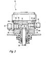
- the high-pressure piston pump 18 includes an elongated housing 34 made of stainless steel is made and in which a cylinder sleeve 36 and a received in this reciprocating piston 38 are. As can be seen in particular from FIG. 2, this is Housing 34 from a commercial drawn Hexagon profile 39, which is a total of six in Has essentially straight side surfaces 40a to 40f. Alternatively, the straight side surfaces could also be used Turning.
- the cylinder liner 36 and the Pistons 38 are arranged in a blind bore 42 which in the central axis of the hexagonal profile 39.
- the Blind bore 42 and piston 38 limit one Work space 44.
- a stepped bore 46 is in the side surface 40a introduced, which over a not shown Inlet valve can communicate with the work space 44 and into which the inlet connector 20 is inserted. He is with that Housing 34 welded in 48.
- the next but one side surface 40c of the Hexagon profile 39 is also a stepped bore 50 available, in which the outlet port 22 is inserted. He is with a weld seam 52 to the housing 34 welded.
- the stepped bore 50 is also a Exhaust valve 54 pressed.
- the stepped bore 50 can also communicate with the work space 44.
- the next but one side surface 40e again introduced a stepped bore 56, in which the electromagnetic actuator 30 and (not visible) the inlet valve is inserted.
- FIGS. 2 and 3 It is readily apparent from FIGS. 2 and 3 that through the shape of the housing 34 as a hexagonal profile 39 the straight side surfaces 40a to 40f the connection of Components, such as the two connecting pieces 20 and 22 and the electromagnetic actuating device 30, is significantly simplified.
- the introduction of the corresponding stepped bores 46, 50, and 56 is in the straight side surfaces 40a, 40c, and 40e simply and with high precision possible.
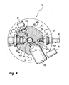
- FIG. 4 An alternative embodiment of a high pressure piston pump 18 is shown in FIG. 4. Such wear Elements and areas that have equivalent functions Elements and areas related to the figures 2 and 3 have illustrated embodiment, the same reference numerals. They are not in detail again explained.
- the inlet connector 20 is not on the side surface 40a, but on the side surface 40b, that is, directly adjacent to the outlet port 22. Furthermore, in the side surface 40f introduced a threaded bore 58 in which is screwed in a pressure sensor 60.
- the Threaded bore 58 communicates with the stepped bore 46, in the inlet connector 20 is attached.
- the pressure sensor 60 is a commercial part, which due to the presence the straight side surface 40f on the housing 34 of the High-pressure piston pump 18 attached and for example over an O-ring 61 can be sealed. By direct Attachment of the pressure sensor 60 to the high pressure piston pump 18 are additional installations in the Line area between the prefeed pump 16 and the High pressure piston pump 18 is not required.
Landscapes
- Engineering & Computer Science (AREA)
- Mechanical Engineering (AREA)
- General Engineering & Computer Science (AREA)
- Chemical & Material Sciences (AREA)
- Combustion & Propulsion (AREA)
- Fuel-Injection Apparatus (AREA)
Priority Applications (2)
| Application Number | Priority Date | Filing Date | Title |
|---|---|---|---|
| EP11153643.9A EP2312148B1 (fr) | 2003-05-20 | 2004-03-24 | pompe à pistons, en particulier pompe d'essence à haute pression |
| EP11153765.0A EP2312149B1 (fr) | 2003-05-20 | 2004-03-24 | pompe à pistons, en particulier pompe d'essence à haute pression |
Applications Claiming Priority (2)
| Application Number | Priority Date | Filing Date | Title |
|---|---|---|---|
| DE2003122602 DE10322602A1 (de) | 2003-05-20 | 2003-05-20 | Kolbenpumpe, insbesondere Hochdruck-Kraftstoffpumpe |
| DE10322602 | 2003-05-20 |
Related Child Applications (2)
| Application Number | Title | Priority Date | Filing Date |
|---|---|---|---|
| EP11153643.9 Division-Into | 2011-02-08 | ||
| EP11153765.0 Division-Into | 2011-02-09 |
Publications (2)
| Publication Number | Publication Date |
|---|---|
| EP1479903A1 true EP1479903A1 (fr) | 2004-11-24 |
| EP1479903B1 EP1479903B1 (fr) | 2011-05-25 |
Family
ID=33039211
Family Applications (3)
| Application Number | Title | Priority Date | Filing Date |
|---|---|---|---|
| EP11153643.9A Expired - Lifetime EP2312148B1 (fr) | 2003-05-20 | 2004-03-24 | pompe à pistons, en particulier pompe d'essence à haute pression |
| EP11153765.0A Expired - Lifetime EP2312149B1 (fr) | 2003-05-20 | 2004-03-24 | pompe à pistons, en particulier pompe d'essence à haute pression |
| EP20040007021 Expired - Lifetime EP1479903B1 (fr) | 2003-05-20 | 2004-03-24 | pompe à pistons, en particulier pompe d'essence à haute pression |
Family Applications Before (2)
| Application Number | Title | Priority Date | Filing Date |
|---|---|---|---|
| EP11153643.9A Expired - Lifetime EP2312148B1 (fr) | 2003-05-20 | 2004-03-24 | pompe à pistons, en particulier pompe d'essence à haute pression |
| EP11153765.0A Expired - Lifetime EP2312149B1 (fr) | 2003-05-20 | 2004-03-24 | pompe à pistons, en particulier pompe d'essence à haute pression |
Country Status (2)
| Country | Link |
|---|---|
| EP (3) | EP2312148B1 (fr) |
| DE (1) | DE10322602A1 (fr) |
Cited By (4)
| Publication number | Priority date | Publication date | Assignee | Title |
|---|---|---|---|---|
| CN107923357A (zh) * | 2015-08-28 | 2018-04-17 | 日立汽车系统株式会社 | 高压燃料泵及其制造方法 |
| DE112018004299T5 (de) | 2017-09-29 | 2020-05-14 | Denso Corporation | Hochdruckpumpe |
| DE112018004297T5 (de) | 2017-09-29 | 2020-05-14 | Denso Corporation | Hochdruckpumpe |
| DE112018005024T5 (de) | 2017-09-29 | 2020-07-09 | Denso Corporation | Hochdruckpumpe |
Citations (7)
| Publication number | Priority date | Publication date | Assignee | Title |
|---|---|---|---|---|
| US2573344A (en) | 1946-09-13 | 1951-10-30 | Everett P Larsh | Fuel injector |
| US3220351A (en) * | 1963-05-28 | 1965-11-30 | Technicon Chromatography Corp | Positive displacement pump |
| US5863187A (en) * | 1997-02-10 | 1999-01-26 | Ivek Corporation | Two position rotary reciprocating pump with liquid displacement flow adjustment |
| EP0900934A2 (fr) * | 1997-09-05 | 1999-03-10 | Denso Corporation | Dispositif d'alimentation en carburant |
| EP1188926A2 (fr) * | 2000-09-19 | 2002-03-20 | Siemens Aktiengesellschaft | Pompe d'alimentation pour rampe d'alimentation en essence |
| US6419459B1 (en) * | 2000-10-02 | 2002-07-16 | Gardner Denver, Inc. | Pump fluid cylinder mounting assembly |
| US6503066B1 (en) * | 2000-06-20 | 2003-01-07 | Curtiss-Wright Flow Control Corporation | Hydrostatic pressure test pump |
-
2003
- 2003-05-20 DE DE2003122602 patent/DE10322602A1/de not_active Withdrawn
-
2004
- 2004-03-24 EP EP11153643.9A patent/EP2312148B1/fr not_active Expired - Lifetime
- 2004-03-24 EP EP11153765.0A patent/EP2312149B1/fr not_active Expired - Lifetime
- 2004-03-24 EP EP20040007021 patent/EP1479903B1/fr not_active Expired - Lifetime
Patent Citations (7)
| Publication number | Priority date | Publication date | Assignee | Title |
|---|---|---|---|---|
| US2573344A (en) | 1946-09-13 | 1951-10-30 | Everett P Larsh | Fuel injector |
| US3220351A (en) * | 1963-05-28 | 1965-11-30 | Technicon Chromatography Corp | Positive displacement pump |
| US5863187A (en) * | 1997-02-10 | 1999-01-26 | Ivek Corporation | Two position rotary reciprocating pump with liquid displacement flow adjustment |
| EP0900934A2 (fr) * | 1997-09-05 | 1999-03-10 | Denso Corporation | Dispositif d'alimentation en carburant |
| US6503066B1 (en) * | 2000-06-20 | 2003-01-07 | Curtiss-Wright Flow Control Corporation | Hydrostatic pressure test pump |
| EP1188926A2 (fr) * | 2000-09-19 | 2002-03-20 | Siemens Aktiengesellschaft | Pompe d'alimentation pour rampe d'alimentation en essence |
| US6419459B1 (en) * | 2000-10-02 | 2002-07-16 | Gardner Denver, Inc. | Pump fluid cylinder mounting assembly |
Cited By (8)
| Publication number | Priority date | Publication date | Assignee | Title |
|---|---|---|---|---|
| CN107923357A (zh) * | 2015-08-28 | 2018-04-17 | 日立汽车系统株式会社 | 高压燃料泵及其制造方法 |
| EP3343015A4 (fr) * | 2015-08-28 | 2018-12-12 | Hitachi Automotive Systems, Ltd. | Pompe à carburant à haute pression et procédé pour sa production |
| US10584668B2 (en) | 2015-08-28 | 2020-03-10 | Hitachi Automotive Systems, Ltd. | High-pressure fuel pump and method for producing same |
| CN107923357B (zh) * | 2015-08-28 | 2020-10-13 | 日立汽车系统株式会社 | 高压燃料泵及其制造方法 |
| DE112018004299T5 (de) | 2017-09-29 | 2020-05-14 | Denso Corporation | Hochdruckpumpe |
| DE112018004297T5 (de) | 2017-09-29 | 2020-05-14 | Denso Corporation | Hochdruckpumpe |
| DE112018005024T5 (de) | 2017-09-29 | 2020-07-09 | Denso Corporation | Hochdruckpumpe |
| US11459991B2 (en) | 2017-09-29 | 2022-10-04 | Denso Corporation | High-pressure pump |
Also Published As
| Publication number | Publication date |
|---|---|
| EP1479903B1 (fr) | 2011-05-25 |
| EP2312148A1 (fr) | 2011-04-20 |
| EP2312149B1 (fr) | 2013-05-22 |
| DE10322602A1 (de) | 2004-12-09 |
| EP2312148B1 (fr) | 2013-10-16 |
| EP2312149A1 (fr) | 2011-04-20 |
Similar Documents
| Publication | Publication Date | Title |
|---|---|---|
| EP0461212B1 (fr) | Pompe d'injection de carburant a commande electrique pour moteurs a combustion interne, en particulier pompe d'injection combinee avec l'injecteur | |
| EP1101931A2 (fr) | Système d'injection à haute pression avec common rail | |
| DE10322603B4 (de) | Kolbenpumpe, insbesondere Hochdruck-Kolbenpumpe für Brennkraftmaschinen mit Direkteinspritzung | |
| WO1999037910A1 (fr) | Systeme de pompes pour alimentation en carburant sous haute pression | |
| DE102006000035A1 (de) | Fluideinspritzventil | |
| EP1519033A2 (fr) | Pompe à piston, notamment pompe haute pression à piston | |
| DE19952513A1 (de) | Kraftstoffeinspritzsystem für Brennkraftmaschinen mit konstantem Lecköldruck im Injektor | |
| EP2312148B1 (fr) | pompe à pistons, en particulier pompe d'essence à haute pression | |
| DE10394136T5 (de) | Kraftstoffeinspritzer für einen Verbrennungsmotor | |
| DE1805024C2 (de) | Aus einer Baueinheit aus Einspritzpumpe und Einspritzventil bestehende Kraftstoffeinspritzvorrichtung für Brennkraftmaschinen | |
| EP2052149B1 (fr) | Dispositif d'injection de carburant dans la chambre de combustion d'un moteur à combustion interne | |
| DE19841642C2 (de) | Radialkolbenpumpe | |
| EP1435454A1 (fr) | Une pièce, qui soutiene une pression interne, surtout pour un moteur à explosion avec une pompe à carburant à haute pression | |
| DE102016220395A1 (de) | Dichtungsring für ein Einspritzventil | |
| DE102004019626B4 (de) | Kraftstoffeinspritzpumpe und Dreh-/Linearbewegungsumwandlungsmechanismus mit Sicherungseinrichtung | |
| EP1403508A2 (fr) | Ensemble d'alimentation de carburant | |
| DE4220619A1 (de) | Einspritzeinrichtung | |
| EP2207958B1 (fr) | Pompe à pistons radiaux à corps de base prismatique pour système d'injection de carburant | |
| EP0906506B1 (fr) | Pompe d'injection de carburant pour moteur a combustion interne | |
| WO2013053593A1 (fr) | Culasse en deux parties pour pompe à carburant haute pression, dotée d'un clapet anti-retour | |
| DE102008041393A1 (de) | Kraftstoffsystem für eine Brennkraftmaschine | |
| DE102005029083B4 (de) | Ölauffanggehäuse für eine Brennkraftmaschine | |
| DE102009054938A1 (de) | Kraftstoffhochdruckpumpe | |
| DE102016201600B4 (de) | Kraftstoffhochdruckpumpe und Kraftstoffeinspritzsystem | |
| EP2387671A1 (fr) | Maître-cylindre |
Legal Events
| Date | Code | Title | Description |
|---|---|---|---|
| PUAI | Public reference made under article 153(3) epc to a published international application that has entered the european phase |
Free format text: ORIGINAL CODE: 0009012 |
|
| AK | Designated contracting states |
Kind code of ref document: A1 Designated state(s): AT BE BG CH CY CZ DE DK EE ES FI FR GB GR HU IE IT LI LU MC NL PL PT RO SE SI SK TR |
|
| AX | Request for extension of the european patent |
Extension state: AL LT LV MK |
|
| 17P | Request for examination filed |
Effective date: 20050524 |
|
| AKX | Designation fees paid |
Designated state(s): DE FR IT |
|
| 17Q | First examination report despatched |
Effective date: 20100322 |
|
| GRAP | Despatch of communication of intention to grant a patent |
Free format text: ORIGINAL CODE: EPIDOSNIGR1 |
|
| GRAS | Grant fee paid |
Free format text: ORIGINAL CODE: EPIDOSNIGR3 |
|
| GRAA | (expected) grant |
Free format text: ORIGINAL CODE: 0009210 |
|
| AK | Designated contracting states |
Kind code of ref document: B1 Designated state(s): DE FR IT |
|
| REG | Reference to a national code |
Ref country code: DE Ref legal event code: R096 Ref document number: 502004012538 Country of ref document: DE Effective date: 20110707 |
|
| PLBE | No opposition filed within time limit |
Free format text: ORIGINAL CODE: 0009261 |
|
| STAA | Information on the status of an ep patent application or granted ep patent |
Free format text: STATUS: NO OPPOSITION FILED WITHIN TIME LIMIT |
|
| 26N | No opposition filed |
Effective date: 20120228 |
|
| REG | Reference to a national code |
Ref country code: DE Ref legal event code: R097 Ref document number: 502004012538 Country of ref document: DE Effective date: 20120228 |
|
| REG | Reference to a national code |
Ref country code: FR Ref legal event code: PLFP Year of fee payment: 13 |
|
| REG | Reference to a national code |
Ref country code: FR Ref legal event code: PLFP Year of fee payment: 14 |
|
| REG | Reference to a national code |
Ref country code: FR Ref legal event code: PLFP Year of fee payment: 15 |
|
| PGFP | Annual fee paid to national office [announced via postgrant information from national office to epo] |
Ref country code: FR Payment date: 20230320 Year of fee payment: 20 |
|
| P01 | Opt-out of the competence of the unified patent court (upc) registered |
Effective date: 20230411 |
|
| PGFP | Annual fee paid to national office [announced via postgrant information from national office to epo] |
Ref country code: IT Payment date: 20230331 Year of fee payment: 20 Ref country code: DE Payment date: 20230524 Year of fee payment: 20 |
|
| REG | Reference to a national code |
Ref country code: DE Ref legal event code: R071 Ref document number: 502004012538 Country of ref document: DE |