EP1479914A1 - Flügelzellenverdichter - Google Patents
Flügelzellenverdichter Download PDFInfo
- Publication number
- EP1479914A1 EP1479914A1 EP03253261A EP03253261A EP1479914A1 EP 1479914 A1 EP1479914 A1 EP 1479914A1 EP 03253261 A EP03253261 A EP 03253261A EP 03253261 A EP03253261 A EP 03253261A EP 1479914 A1 EP1479914 A1 EP 1479914A1
- Authority
- EP
- European Patent Office
- Prior art keywords
- rotor
- segment
- opposite
- outlet
- sliding vane
- Prior art date
- Legal status (The legal status is an assumption and is not a legal conclusion. Google has not performed a legal analysis and makes no representation as to the accuracy of the status listed.)
- Withdrawn
Links
- 239000012530 fluid Substances 0.000 claims abstract description 27
- 238000007599 discharging Methods 0.000 claims abstract description 13
- 238000007789 sealing Methods 0.000 claims description 3
- 230000007423 decrease Effects 0.000 claims description 2
- 230000002411 adverse Effects 0.000 description 1
- 238000013459 approach Methods 0.000 description 1
- 230000006835 compression Effects 0.000 description 1
- 238000007906 compression Methods 0.000 description 1
- 230000000694 effects Effects 0.000 description 1
Images


Classifications
-
- F—MECHANICAL ENGINEERING; LIGHTING; HEATING; WEAPONS; BLASTING
- F04—POSITIVE - DISPLACEMENT MACHINES FOR LIQUIDS; PUMPS FOR LIQUIDS OR ELASTIC FLUIDS
- F04C—ROTARY-PISTON, OR OSCILLATING-PISTON, POSITIVE-DISPLACEMENT MACHINES FOR LIQUIDS; ROTARY-PISTON, OR OSCILLATING-PISTON, POSITIVE-DISPLACEMENT PUMPS
- F04C18/00—Rotary-piston pumps specially adapted for elastic fluids
- F04C18/30—Rotary-piston pumps specially adapted for elastic fluids having the characteristics covered by two or more of groups F04C18/02, F04C18/08, F04C18/22, F04C18/24, F04C18/48, or having the characteristics covered by one of these groups together with some other type of movement between co-operating members
- F04C18/34—Rotary-piston pumps specially adapted for elastic fluids having the characteristics covered by two or more of groups F04C18/02, F04C18/08, F04C18/22, F04C18/24, F04C18/48, or having the characteristics covered by one of these groups together with some other type of movement between co-operating members having the movement defined in group F04C18/08 or F04C18/22 and relative reciprocation between the co-operating members
- F04C18/344—Rotary-piston pumps specially adapted for elastic fluids having the characteristics covered by two or more of groups F04C18/02, F04C18/08, F04C18/22, F04C18/24, F04C18/48, or having the characteristics covered by one of these groups together with some other type of movement between co-operating members having the movement defined in group F04C18/08 or F04C18/22 and relative reciprocation between the co-operating members with vanes reciprocating with respect to the inner member
- F04C18/3441—Rotary-piston pumps specially adapted for elastic fluids having the characteristics covered by two or more of groups F04C18/02, F04C18/08, F04C18/22, F04C18/24, F04C18/48, or having the characteristics covered by one of these groups together with some other type of movement between co-operating members having the movement defined in group F04C18/08 or F04C18/22 and relative reciprocation between the co-operating members with vanes reciprocating with respect to the inner member the inner and outer member being in contact along one line or continuous surface substantially parallel to the axis of rotation
Definitions
- This invention relates to a rotary compressor, more particularly to a rotary compressor having a rotor with a sliding vane that extends radially through the rotating axis of the rotor.
- a conventional sliding-vane type rotary compressor normally includes a cylinder formed with an inlet and an outlet, and a rotor disposed eccentrically and rotatably in the cylinder and formed with a plurality of angularly spaced apart slots.
- the cylinder and the rotor cooperatively define a chamber therebetween.
- a plurality of vanes are respectively and slidably received in the slots so as to divide the chamber into a plurality of independent sub-chambers.
- Each sub-chamber receives fluid from the inlet upon passing by the inlet.
- the fluid in each sub-chamber is gradually compressed when the sub-chamber approaches to the outlet, and is discharged at the outlet to an external container.
- a pressure-regulating valve is connected to the container for controlling the pressure in the container.
- the aforesaid conventional rotary compressor is disadvantageous in that friction among the vanes and an inner wall of the cylinder is relatively large during rotation of the rotor, which results in high temperature of the rotary compressor, which has an adverse effect on the performance of the rotary compressor, and which can result in a shorter service life for the rotary compressor.
- the object of the present invention is to provide a rotary compressor that can overcome the aforementioned drawback of the prior art.
- a rotary compressor that comprises: a cylinder having an inner wall that defines an inner space therein, and formed with an inlet that is in fluid communication with the inner space, and an outlet which is spaced apart from the inlet and which is in fluid communication with the inner space; a rotor mounted rotatably in the inner space and defining a sliding space, the rotor and the inner wall of the cylinder cooperatively defining a chamber therebetween, the rotor being rotatable about an axis in a rotating direction, the chamber being in fluid communication with the inlet and the outlet, the sliding space being in spatial communication with the chamber, extending through the axis in a radial direction relative to the axis, and having two opposite ends opposite to each other in the radial direction, the rotor being eccentrically disposed in the inner space and being in close proximity to a portion of the inner wall at a position between the inlet and the outlet; and a sliding vane mounted slidingly in the sliding space, extending in the
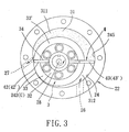
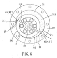
- Figs. 1 to 6 illustrate the preferred embodiment of a rotary compressor according to the present invention.
- the rotary compressor includes: a cylinder 22 having an inner wall 24 that defines an inner space 20 therein, and formed with an inlet 26 that is in fluid communication with the inner space 20, and an outlet 27 which is angularly spaced apart from the inlet 26 and which is in fluid communication with the inner space 20; a rotor 3 mounted rotatably in the inner space 20 and defining a sliding space 34, the rotor 3 and the inner wall 24 of the cylinder 22 cooperatively defining a chamber 31 therebetween, the rotor 3 being rotatable about an axis 28 in a rotating direction, the chamber 31 being in fluid communication with the inlet 26 and the outlet 27, the sliding space 34 being in spatial communication with the chamber 31, extending through the axis 28 in a radial direction relative to the axis 28, and having two opposite ends opposite to each other in the radial direction, the rotor 3 being eccentrically disposed in the inner space 20 and being in
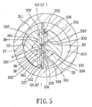
- the sliding vane 4 is in the form of a plate that has an H-shaped portion 40 which includes parallel first and second leaves 42', 43' and a middle rib 41 interconnecting the first and second leaves 42' , 43'.
- the first and second leaves 42', 43' are opposite to each other in the radial direction, and respectively define the opposite ends 42, 43 of the sliding vane 4.
- the cross-section of the chamber 31 gradually increases from a position proximate to the portion 242 of the inner wall 24 to an opposite position 245 diametrically opposite to the portion 242 of the inner wall 24, and gradually decreases from the opposite position 245 to the outlet 27.
- the rotor 3 is cylindrical in shape, and includes first and second halves 33, 33' which cooperatively define the sliding space 34 therebetween.
- the cylinder 22 has opposite upper and lower open ends 221, 222 and upper and lower sealing flanges 23, 21 that are fixed sealingly and respectively to the upper and lower open ends 221, 222 and that are respectively formed with central openings 230, 210.
- the first and second halves 33, 33' of the rotor 3 are indented in an axial direction relative to the rotor 3 to form opposite upper and lower recesses 330.
- the rotary compressor further includes upper and lower bearings 231, 211 that are respectively received in the central openings 230, 210 in the upper and lower flanges 23, 21, and upper and lower journals 32 that respectively have upper and lower limiting flanges 320 which are respectively received in the upper and lower recesses 330 and which are secured to the rotor 3, and upper and lower shafts 322 which extend respectively and outwardly of the cylinder 22 from the upper and lower limiting flanges 320 through the upper and lower bearings 231, 211.
- Each of the upper and lower limiting flanges 320 has a periphery edge 3201, and a pair of opposite radial slits 321 that extend inwardly and radially from the periphery edge 3201.
- the first and second leaves 42', 43' of the sliding vane 4 have upper and lower ends that are respectively received in the slits 321 in the upper and lower limiting flanges 320.
- a pulley 5 is connected to the upper shaft 322 of the upper journal 32 for driving the latter.
- Each of the first and second halves 33 (33') of the rotor 3 has opposite outer and inner surfaces 339 (339'), 331 (331') extending angularly of the rotor 3, and opposite first and second ends 337 (337'), 338 (338') opposite to each other in the radial direction.
- the first and second ends 337 (337'), 338 (338') of each of the first and second halves 33 (33') of the rotor 3 respectively confront the first and second leaves 42', 43' of the sliding vane 4.
- the rotor 3 further includes first and second tubular elements 335, 335', and is formed with a first channel 38 (see Fig.
- the first channel 38 has a first segment 381 that is formed in the first half 33 of the rotor 3, and a second segment 382 that is formed in the second half 33' of the rotor 3.
- the first segment 381 of the first channel 38 has an inlet port 336 that is formed in the outer surface 339 of the first half 33 of the rotor 3, and a first connecting port 334 that is formed in the inner surface 331 of the first half 33 of the rotor 3.
- the second segment 382 of the first channel 38 has a second connecting port 333' that is formed in the inner surface 331' of the second half 33' of the rotor 3 and that is connected to and that is in fluid communication with the first connecting port 334 through the first tubular element 335, and an outlet port 332' that is formed in the first end 337' of the second half 33' of the rotor 3 and that confronts the first leaf 42' of the sliding vane 4.
- the second channel 39 has a first segment 391 that is formed in the second half 33' of the rotor 3, and a second segment 392 that is formed in the first half 33 of the rotor 3.
- the first segment 391 of the second channel 39 has an inlet port 336' that is formed in the outer surface 339' of the second half 33' of the rotor 3, and a first connecting port 334' that is formed in the inner surface 331' of the second half 33' of the rotor 3.
- the second segment 392 of the second channel 39 has a second connecting port 333 that is formed in the inner surface 331 of the first half 33 of the rotor 3 and that is connected to and that is in fluid communication with the first connecting port 334' of the second channel 39 through the second tubular element 335', and an outlet port 332 that is formed in the second end 338 of the first half 33 of the rotor 3 and that confronts the second leaf 43' of the sliding vane 4.
- the inlet port 336 (336') of the first segment 381 (391) of each of the first and second channels 38 (39) is disposed anteriorly of the respective one of the first and second leaves 42' , 43' in the rotating direction, while the outlet port 332 (332') of the second segment 382 (392) of each of the first and second channels 38 (39) is disposed posteriorly of the respective one of the first and second leaves 42', 43' in the rotating direction.
- compression of the fluid in the discharging segment 311 results in a force that pushes the respective one of the first and second leaves 42', 43' (which is the second leaf 43' when the rotor 3 rotates to the position shown in Fig.
- the weight of the sliding vane 4 is relatively light by virtue of its configuration so as to reduce the momentum of the sliding vane 4 when sliding in the sliding space 34.
- the inner wall 24 of the cylinder 22 is divided into different segments which have different curvatures in such a manner that the sliding vane 4 can smoothly rotate from a first position shown in Fig. 6 through a second position shown in Fig. 3 (where the sliding vane 4 passed by the outlet 27 in the cylinder 22) to a third position (where the sliding vane 4 passes by the portion 242 of the inner wall 24 of the cylinder 22) shown in Fig. 4, and that the rotary compressor can be operated quietly.
Landscapes
- Engineering & Computer Science (AREA)
- Mechanical Engineering (AREA)
- General Engineering & Computer Science (AREA)
- Rotary Pumps (AREA)
Priority Applications (2)
| Application Number | Priority Date | Filing Date | Title |
|---|---|---|---|
| US10/395,391 US20040191104A1 (en) | 2003-03-25 | 2003-03-25 | Rotary compressor having a rotor with a sliding vane |
| EP03253261A EP1479914A1 (de) | 2003-03-25 | 2003-05-23 | Flügelzellenverdichter |
Applications Claiming Priority (2)
| Application Number | Priority Date | Filing Date | Title |
|---|---|---|---|
| US10/395,391 US20040191104A1 (en) | 2003-03-25 | 2003-03-25 | Rotary compressor having a rotor with a sliding vane |
| EP03253261A EP1479914A1 (de) | 2003-03-25 | 2003-05-23 | Flügelzellenverdichter |
Publications (1)
| Publication Number | Publication Date |
|---|---|
| EP1479914A1 true EP1479914A1 (de) | 2004-11-24 |
Family
ID=33477647
Family Applications (1)
| Application Number | Title | Priority Date | Filing Date |
|---|---|---|---|
| EP03253261A Withdrawn EP1479914A1 (de) | 2003-03-25 | 2003-05-23 | Flügelzellenverdichter |
Country Status (2)
| Country | Link |
|---|---|
| US (1) | US20040191104A1 (de) |
| EP (1) | EP1479914A1 (de) |
Cited By (3)
| Publication number | Priority date | Publication date | Assignee | Title |
|---|---|---|---|---|
| DE102004034919B3 (de) * | 2004-07-09 | 2005-12-01 | Joma-Hydromechanic Gmbh | Einflügelvakuumpumpe |
| EP1707816A1 (de) * | 2005-03-31 | 2006-10-04 | Joma-Hydromechanic GmbH | Vakuumpumpe |
| WO2020015284A1 (zh) * | 2018-07-18 | 2020-01-23 | 珠海格力电器股份有限公司 | 泵体组件、流体机械及换热设备 |
Families Citing this family (1)
| Publication number | Priority date | Publication date | Assignee | Title |
|---|---|---|---|---|
| CN102943757A (zh) * | 2012-10-23 | 2013-02-27 | 即墨市振华电机厂 | 摆动转子压缩机 |
Citations (6)
| Publication number | Priority date | Publication date | Assignee | Title |
|---|---|---|---|---|
| GB191122712A (en) * | 1910-10-17 | 1911-11-30 | Giulio Silvestri | Improvements in and relating to Rotary Engines. |
| GB528034A (en) * | 1939-12-06 | 1940-10-21 | Gavin Ralston | Improvements in rotary liquid pressure motors |
| US2282642A (en) * | 1940-05-17 | 1942-05-12 | Curtis Pump Co | Vane structure for rotary pumps |
| EP0264778A2 (de) * | 1986-10-18 | 1988-04-27 | B a r m a g AG | Flügelzellenpumpe |
| US5758501A (en) * | 1995-03-08 | 1998-06-02 | Jirnov; Olga | Sliding-blade vapor engine with vortex boiler |
| DE20018958U1 (de) * | 2000-11-07 | 2002-03-21 | Joma-Hydromechanic GmbH, 72411 Bodelshausen | Schieber zum gegenseitigen Trennen der beiden Kammern im Gehäuseraum einer Flügelzellenpumpe oder eines solchen Motors |
Family Cites Families (4)
| Publication number | Priority date | Publication date | Assignee | Title |
|---|---|---|---|---|
| US1848670A (en) * | 1932-03-08 | Pitman counterbalance | ||
| US1972744A (en) * | 1923-01-11 | 1934-09-04 | Lister William | Rotary piston and cylinder construction |
| US2410596A (en) * | 1943-11-09 | 1946-11-05 | Aaron C Bradford | Sliding vane engine or pump |
| US3386648A (en) * | 1967-01-31 | 1968-06-04 | Walter J. Van Rossem | Rotary vane type pump |
-
2003
- 2003-03-25 US US10/395,391 patent/US20040191104A1/en not_active Abandoned
- 2003-05-23 EP EP03253261A patent/EP1479914A1/de not_active Withdrawn
Patent Citations (6)
| Publication number | Priority date | Publication date | Assignee | Title |
|---|---|---|---|---|
| GB191122712A (en) * | 1910-10-17 | 1911-11-30 | Giulio Silvestri | Improvements in and relating to Rotary Engines. |
| GB528034A (en) * | 1939-12-06 | 1940-10-21 | Gavin Ralston | Improvements in rotary liquid pressure motors |
| US2282642A (en) * | 1940-05-17 | 1942-05-12 | Curtis Pump Co | Vane structure for rotary pumps |
| EP0264778A2 (de) * | 1986-10-18 | 1988-04-27 | B a r m a g AG | Flügelzellenpumpe |
| US5758501A (en) * | 1995-03-08 | 1998-06-02 | Jirnov; Olga | Sliding-blade vapor engine with vortex boiler |
| DE20018958U1 (de) * | 2000-11-07 | 2002-03-21 | Joma-Hydromechanic GmbH, 72411 Bodelshausen | Schieber zum gegenseitigen Trennen der beiden Kammern im Gehäuseraum einer Flügelzellenpumpe oder eines solchen Motors |
Cited By (4)
| Publication number | Priority date | Publication date | Assignee | Title |
|---|---|---|---|---|
| DE102004034919B3 (de) * | 2004-07-09 | 2005-12-01 | Joma-Hydromechanic Gmbh | Einflügelvakuumpumpe |
| EP1707816A1 (de) * | 2005-03-31 | 2006-10-04 | Joma-Hydromechanic GmbH | Vakuumpumpe |
| WO2020015284A1 (zh) * | 2018-07-18 | 2020-01-23 | 珠海格力电器股份有限公司 | 泵体组件、流体机械及换热设备 |
| US12286972B2 (en) | 2018-07-18 | 2025-04-29 | Gree Electric Appliances, Inc. Of Zhuhai | Pump body assembly, fluid machinery, and heat exchange device |
Also Published As
| Publication number | Publication date |
|---|---|
| US20040191104A1 (en) | 2004-09-30 |
Similar Documents
| Publication | Publication Date | Title |
|---|---|---|
| US8075292B2 (en) | Eccentric rotor compressor | |
| US4451215A (en) | Rotary piston apparatus | |
| US5304049A (en) | Frictionless rotary pump-motor-meter | |
| US5536153A (en) | Non-contact vane-type fluid displacement machine with lubricant separator and sump arrangement | |
| JP2013527379A (ja) | 可変容積形潤滑剤ポンプ | |
| CN101517238B (zh) | 具有叶片的旋转泵 | |
| US5015161A (en) | Multiple stage orbiting ring rotary compressor | |
| US20250369440A1 (en) | Rotary pump or motor with improved intake, exhaust, vane and bearingless sleeve features | |
| EP0058456A1 (de) | Gleitschieber-Drehkolbenpumpe oder -motor | |
| EP1479914A1 (de) | Flügelzellenverdichter | |
| JP2678439B2 (ja) | 可変容量ポンプの改良 | |
| US5560741A (en) | Non-contact vane-type fluid displacement machine with rotor and vane positioning | |
| JP3763843B2 (ja) | 回転単羽根ガスコンプレッサ | |
| KR970062340A (ko) | 로터형 펌프 | |
| US4003682A (en) | Rotary piston engine having continuous torque characteristics | |
| KR970075376A (ko) | 로터형 펌프 | |
| US4846638A (en) | Rotary fluid machine with pivoted vanes | |
| US4822265A (en) | Pump rotor | |
| US5074769A (en) | Compressor having an orbital rotor with parallel linkage and spring biased vanes | |
| GB2063367A (en) | Sliding-vane rotary fluid-machines | |
| US5452998A (en) | Non-contact vane-type fluid displacement machine with suction flow check valve assembly | |
| WO2020159382A1 (en) | Rotation machine | |
| US1019499A (en) | Positive-pressure blower. | |
| JP2588911Y2 (ja) | 回転式圧縮機 | |
| GB2425151A (en) | Vacuum pump with passage in dividing plate and shaped flutter valve |
Legal Events
| Date | Code | Title | Description |
|---|---|---|---|
| PUAI | Public reference made under article 153(3) epc to a published international application that has entered the european phase |
Free format text: ORIGINAL CODE: 0009012 |
|
| AK | Designated contracting states |
Kind code of ref document: A1 Designated state(s): AT BE BG CH CY CZ DE DK EE ES FI FR GB GR HU IE IT LI LU MC NL PT RO SE SI SK TR |
|
| AX | Request for extension of the european patent |
Extension state: AL LT LV MK |
|
| AKX | Designation fees paid | ||
| REG | Reference to a national code |
Ref country code: DE Ref legal event code: 8566 |
|
| STAA | Information on the status of an ep patent application or granted ep patent |
Free format text: STATUS: THE APPLICATION IS DEEMED TO BE WITHDRAWN |
|
| 18D | Application deemed to be withdrawn |
Effective date: 20050525 |