EP1479921B1 - Dispositif d'arrêt avec un actuateur à mémoire de forme - Google Patents
Dispositif d'arrêt avec un actuateur à mémoire de forme Download PDFInfo
- Publication number
- EP1479921B1 EP1479921B1 EP04010273A EP04010273A EP1479921B1 EP 1479921 B1 EP1479921 B1 EP 1479921B1 EP 04010273 A EP04010273 A EP 04010273A EP 04010273 A EP04010273 A EP 04010273A EP 1479921 B1 EP1479921 B1 EP 1479921B1
- Authority
- EP
- European Patent Office
- Prior art keywords
- shape memory
- stop
- stop elements
- cam means
- mutual
- Prior art date
- Legal status (The legal status is an assumption and is not a legal conclusion. Google has not performed a legal analysis and makes no representation as to the accuracy of the status listed.)
- Expired - Lifetime
Links
Images


Classifications
-
- E—FIXED CONSTRUCTIONS
- E05—LOCKS; KEYS; WINDOW OR DOOR FITTINGS; SAFES
- E05B—LOCKS; ACCESSORIES THEREFOR; HANDCUFFS
- E05B47/00—Operating or controlling locks or other fastening devices by electric or magnetic means
- E05B47/0001—Operating or controlling locks or other fastening devices by electric or magnetic means with electric actuators; Constructional features thereof
- E05B47/0009—Operating or controlling locks or other fastening devices by electric or magnetic means with electric actuators; Constructional features thereof with thermo-electric actuators, e.g. heated bimetals
-
- F—MECHANICAL ENGINEERING; LIGHTING; HEATING; WEAPONS; BLASTING
- F03—MACHINES OR ENGINES FOR LIQUIDS; WIND, SPRING, OR WEIGHT MOTORS; PRODUCING MECHANICAL POWER OR A REACTIVE PROPULSIVE THRUST, NOT OTHERWISE PROVIDED FOR
- F03G—SPRING, WEIGHT, INERTIA OR LIKE MOTORS; MECHANICAL-POWER PRODUCING DEVICES OR MECHANISMS, NOT OTHERWISE PROVIDED FOR OR USING ENERGY SOURCES NOT OTHERWISE PROVIDED FOR
- F03G7/00—Mechanical-power-producing mechanisms, not otherwise provided for or using energy sources not otherwise provided for
- F03G7/06—Mechanical-power-producing mechanisms, not otherwise provided for or using energy sources not otherwise provided for using expansion or contraction of bodies due to heating, cooling, moistening, drying or the like
- F03G7/061—Mechanical-power-producing mechanisms, not otherwise provided for or using energy sources not otherwise provided for using expansion or contraction of bodies due to heating, cooling, moistening, drying or the like characterised by the actuating element
- F03G7/0614—Mechanical-power-producing mechanisms, not otherwise provided for or using energy sources not otherwise provided for using expansion or contraction of bodies due to heating, cooling, moistening, drying or the like characterised by the actuating element using shape memory elements
- F03G7/06143—Wires
-
- F—MECHANICAL ENGINEERING; LIGHTING; HEATING; WEAPONS; BLASTING
- F03—MACHINES OR ENGINES FOR LIQUIDS; WIND, SPRING, OR WEIGHT MOTORS; PRODUCING MECHANICAL POWER OR A REACTIVE PROPULSIVE THRUST, NOT OTHERWISE PROVIDED FOR
- F03G—SPRING, WEIGHT, INERTIA OR LIKE MOTORS; MECHANICAL-POWER PRODUCING DEVICES OR MECHANISMS, NOT OTHERWISE PROVIDED FOR OR USING ENERGY SOURCES NOT OTHERWISE PROVIDED FOR
- F03G7/00—Mechanical-power-producing mechanisms, not otherwise provided for or using energy sources not otherwise provided for
- F03G7/06—Mechanical-power-producing mechanisms, not otherwise provided for or using energy sources not otherwise provided for using expansion or contraction of bodies due to heating, cooling, moistening, drying or the like
- F03G7/063—Mechanical-power-producing mechanisms, not otherwise provided for or using energy sources not otherwise provided for using expansion or contraction of bodies due to heating, cooling, moistening, drying or the like characterised by the mechanic interaction
- F03G7/0636—Mechanical-power-producing mechanisms, not otherwise provided for or using energy sources not otherwise provided for using expansion or contraction of bodies due to heating, cooling, moistening, drying or the like characterised by the mechanic interaction with several elements connected in parallel
-
- F—MECHANICAL ENGINEERING; LIGHTING; HEATING; WEAPONS; BLASTING
- F16—ENGINEERING ELEMENTS AND UNITS; GENERAL MEASURES FOR PRODUCING AND MAINTAINING EFFECTIVE FUNCTIONING OF MACHINES OR INSTALLATIONS; THERMAL INSULATION IN GENERAL
- F16C—SHAFTS; FLEXIBLE SHAFTS; ELEMENTS OR CRANKSHAFT MECHANISMS; ROTARY BODIES OTHER THAN GEARING ELEMENTS; BEARINGS
- F16C2202/00—Solid materials defined by their properties
- F16C2202/20—Thermal properties
- F16C2202/28—Shape memory material
-
- Y—GENERAL TAGGING OF NEW TECHNOLOGICAL DEVELOPMENTS; GENERAL TAGGING OF CROSS-SECTIONAL TECHNOLOGIES SPANNING OVER SEVERAL SECTIONS OF THE IPC; TECHNICAL SUBJECTS COVERED BY FORMER USPC CROSS-REFERENCE ART COLLECTIONS [XRACs] AND DIGESTS
- Y10—TECHNICAL SUBJECTS COVERED BY FORMER USPC
- Y10T—TECHNICAL SUBJECTS COVERED BY FORMER US CLASSIFICATION
- Y10T403/00—Joints and connections
- Y10T403/21—Utilizing thermal characteristic, e.g., expansion or contraction, etc.
Definitions
- the present invention refers to a stop device usable in any application wherein it is necessary to arrange a deactivable stop device for avoiding the movement, at least in one direction, of a first moving structure with respect to a second structure.
- the object of the A deactivable stop device in described in W0-A-0179107 invention is to carry out a stop device which shows a simple structure, with reduced hindrance, economical to produce and at the same time is effective in the functioning.
- the object of the invention is a stop device having the features defined in the enclosed claim 1. Further advantageous features of the invention are defined in the remaining dependent claims.
- numeral 1 generally shows a fixed support structure comprising a box shaped body of a metal sheet 2 with two end flanges 3, 4 for allowing the mounting of the structure 1 on any structure which is designed to receive the same.
- two stop elements 5 are slidably mounted, which are movable between a mutual distant position, that can be seen in figure 3, and a mutual close position.
- the two stop elements 5 are designed to co-operate with a stop surface (not shown) arranged over a structure, at which respect the structure carrying the device according to the invention is movable, in order to determine a stop position of a structure with respect to the other.
- a stop surface not shown
- these structures mutually movable therebetween are not shown, as the device forming the object of the invention is of a general application.
- the stop device-carrying structure can be a retractable bumper of a motor vehicle.
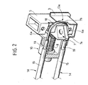
- first and a second coil springs 6 are associated (one of which is partially visible in figure 5), which are arranged according to the hole axes 6a of the stop element 5 that can be seen in figure 2. Coils 6 are arranged for operating under traction in order to tend to maintain the two stop elements 5 towards their mutual close position.
- the two stop elements 5 have two slanted surfaces 5a facing each other, substantially V-shaped, which co-operate with the two opposite slanted sides 7a of a wedge-shaped element 7, acting as a cam, which is pushed by two coil springs 8 leftwards (with reference to figure 3) in order to hold the two stop elements 5 in their mutual distant position, against the action of the springs 6.
- the wedge-shaped element 7 then acts as a cam which makes the two stop elements 5 coming out from the box body 2 due to the engagement of the opposite inclined planes 7a, 5a.
- the movement of the wedge-shaped element 7 is driven within two bushings 9 fixed to a bracket 10 belonging to the fixed support structure 1, within which two cylindrical pins 11 are slidably mounted and fixed at one end to the wedge-shaped element 7.
- a shape memory actuator In order to return the two stop elements 5 towards their mutual close position, a shape memory actuator, generally referred with the numeral 12, is arranged, which in the illustrated example includes a shape memory wire 13 arranged according to a general U-shaped configuration, with two branches 14 substantially parallel, and.an intermediate joining portion 13a engaged around a curved groove of a guide element 7b fixed to the wedge-shaped element 7 (see figure 2).
- the two opposite and adjacent ends of the shape memory wire 13 are rigidly connected with the fixed support structure 1. This is obtained by using two metal rigid tubes 15, each having one end fixed to the bracket 10 with the opposite end having a metal bushing 16 with a H-shaped section, within which a block 17, fixed to the respective end of the flexible cable 13, is mounted.
- the cable 13 is formed by extrusion of a shape memory metal alloy.
- a synthetic material coating 18 is obtained, like the one which is the object of the previous patent application of the Applicant EP-A-1443227.
- the function of this coating will result apparent in the following.
- the whole of the wire 13 with its co-extruded sheath 18 is arranged through a sheath 19 (figure 2) which has one end fixed to the bracket 10 as well, and the opposite end ending against the cross sector of the bushing 16.
- Means (not illustrated) for supplying an electric current through the wire 13 are also provided.
- the wire 13 becomes warm and, due to the shape memory, it undergoes a length reduction. Since the two opposite ends of the wire are fixed to the bushings 16, which are rigidly connected to the fixed support structure 1, the shortening of the wire causes a displacement of the intermediate joining portion 13a of the wire in the direction of the two adjacent ends of the wire, namely a displacement of the wedge-shaped element 7 (see figure 3) rightwards (always referring to figure 3), against the action of the springs 8.
- the shape memory element could also be a rigid elengated element.
Landscapes
- Engineering & Computer Science (AREA)
- Chemical & Material Sciences (AREA)
- Combustion & Propulsion (AREA)
- Mechanical Engineering (AREA)
- General Engineering & Computer Science (AREA)
- Electric Cable Arrangement Between Relatively Moving Parts (AREA)
- Vehicle Body Suspensions (AREA)
- Transmission Devices (AREA)
- Installation Of Indoor Wiring (AREA)
- Control Of Position Or Direction (AREA)
- Supports For Pipes And Cables (AREA)
- Details Of Indoor Wiring (AREA)
- Bending Of Plates, Rods, And Pipes (AREA)
- Information Transfer Systems (AREA)
Claims (10)
- Dispositif d'arrêt, comprenant :- une structure support fixe (1) ;- une paire d'éléments d'arrêt (5) montés pour un coulissement à l'intérieur de la structure support (1) et déplaçables entre une position dans laquelle ils sont proches l'un de l'autre et une position dans laquelle ils sont distants l'un de l'autre, dans lequel ils font saillie à partir des côtés opposés de la structure support fixe (1) pour la mise en prise avec une surface d'arrêt correspondante ;- des premiers moyens de ressort (6) qui ont tendance à ramener les deux éléments d'arrêt (5) à la position dans laquelle ils sont proches l'un de l'autre ;- des moyens de came (7) pour pousser les deux éléments d'arrêt (5) vers la position dans laquelle ils sont distants l'un de l'autre, à l'encontre de l'action desdits premiers moyens de ressort (6) ;- des deuxièmes moyens de ressort (8) pour pousser les moyens de came (7) vers une position dans laquelle ils maintiennent les deux éléments d'arrêt (5) dans la position dans laquelle ils sont distants l'un de l'autre ; et- un actuateur à mémoire de forme (12) pour ramener lesdits moyens de came, à l'encontre de l'action desdits deuxièmes moyens de ressort, vers une position dans laquelle les deux éléments d'arrêt (5) peuvent se déplacer librement sur la position dans laquelle ils sont proches l'un de l'autre, sous l'action desdits premiers moyens de ressort (6).
- Dispositif d'arrêt selon la revendication 1, caractérisé en ce que ledit actuateur (12) comprend au moins un ou plusieurs fils à mémoire de forme intercalés entre la structure support fixe (1) et lesdits moyens de came, et des moyens pour faire passer un courant électrique à travers les fils à mémoire de forme susmentionnés (13), de manière à provoquer le chauffage et le raccourcissement consécutif qui est du à l'effet de mémoire de forme, ce qui provoque ainsi un déplacement des moyens de came susmentionnés (7) vers une position dans laquelle ils autorisent le déplacement vers l'arrière des deux éléments d'arrêt (5) vers la position dans laquelle ils sont proches l'un de l'autre.
- Dispositif selon la revendication 2, caractérisé en ce qu'il comprend deux fils agencés en parallèle entre une structure fixe et des moyens de came.
- Dispositif selon la revendication 3, caractérisé en ce que les deux fils sont définis par deux branches d'un seul et unique fil retourné en U autour desdits moyens de came.
- Dispositif selon la revendication 1, caractérisé en ce que les moyens de came susmentionnés se composent d'un unique élément en forme de coin (7) présentant deux côtés opposés inclinés en forme de V (7a) qui se mettent en prise avec des surfaces inclinées l'une en face de l'autre (5a) des deux éléments d'arrêt (5).
- Dispositif d'arrêt selon la revendication 5, caractérisé en ce que ledit élément en forme de coin (7) comporte une partie (7b) qui est pourvue d'une rainure semi circonférentielle pour l'engagement dudit fil à mémoire de forme (13).
- Dispositif selon la revendication 4, caractérisé en ce que le fil à mémoire de forme susmentionné est obtenu par extrusion en même temps qu'un revêtement en matériau synthétique (18).
- Dispositif selon la revendication 7, caractérisé en ce que les extrémités adjacentes opposées du fil à mémoire de forme (13) sont connectées à deux bagues (16) qui sont fixées toutes les deux à l'extrémité d'un tube en métal (15) raccordé à la structure support (1).
- Dispositif selon la revendication 8, caractérisé en ce que, à l'intérieur dudit tube en métal (15), une gaine (19) est agencée, qui est traversée par le fil à mémoire de forme susmentionné (13) avec le revêtement co-extrudé relatif (18).
- Dispositif selon la revendication 5, caractérisé en ce que les côtés opposés inclinés (7a) de l'élément en forme de coin (7) forment un V sur un plan orthogonal par rapport au plan défini par les deux branches parallèles du fil à mémoire de forme (13).
Applications Claiming Priority (2)
| Application Number | Priority Date | Filing Date | Title |
|---|---|---|---|
| IT000366A ITTO20030366A1 (it) | 2003-05-20 | 2003-05-20 | Dispositivo di arresto con attuatore a memoria di forma. |
| ITTO20030366 | 2003-05-20 |
Publications (2)
| Publication Number | Publication Date |
|---|---|
| EP1479921A1 EP1479921A1 (fr) | 2004-11-24 |
| EP1479921B1 true EP1479921B1 (fr) | 2006-04-05 |
Family
ID=33042729
Family Applications (1)
| Application Number | Title | Priority Date | Filing Date |
|---|---|---|---|
| EP04010273A Expired - Lifetime EP1479921B1 (fr) | 2003-05-20 | 2004-04-30 | Dispositif d'arrêt avec un actuateur à mémoire de forme |
Country Status (8)
| Country | Link |
|---|---|
| US (1) | US7073332B2 (fr) |
| EP (1) | EP1479921B1 (fr) |
| JP (1) | JP2004345631A (fr) |
| CN (1) | CN1573134A (fr) |
| AT (1) | ATE322626T1 (fr) |
| DE (1) | DE602004000587T2 (fr) |
| ES (1) | ES2259164T3 (fr) |
| IT (1) | ITTO20030366A1 (fr) |
Families Citing this family (22)
| Publication number | Priority date | Publication date | Assignee | Title |
|---|---|---|---|---|
| US20060172557A1 (en) * | 2004-09-09 | 2006-08-03 | He Xinhua Sam | Electrical actuator having smart muscle wire |
| ATE350527T1 (de) * | 2004-07-13 | 2007-01-15 | Fiat Ricerche | Maschine zum waschen und/oder trocknen von wäsche,mit einer elektrisch betätigbaren verriegelungs- /entriegelungsvorrichtung der tür |
| US20080127684A1 (en) * | 2004-07-14 | 2008-06-05 | Telezygology Inc. | Release for Fastening Assembly |
| ITTO20040691A1 (it) * | 2004-10-08 | 2005-01-08 | Elbi Int Spa | Dispositivo di bloccaggio per un elemento mobile, in particolare per un cestello portabiancheria di una macchina lavatrice a carica dall'alto |
| ATE360761T1 (de) * | 2004-12-30 | 2007-05-15 | Fiat Ricerche | Formgedächtnisbetätigungseinrichtung mit überspannungsschädensschutz |
| JP4600068B2 (ja) * | 2005-02-10 | 2010-12-15 | コニカミノルタホールディングス株式会社 | 製作装置および製作方法 |
| TW200640743A (en) * | 2005-04-04 | 2006-12-01 | Telezygology Inc | Quick release system |
| DE602005008400D1 (de) * | 2005-05-27 | 2008-09-04 | Fiat Ricerche | Kraftfahrzeugtür mit Kurzhubabsenkung der Fensterscheibe |
| JP2007253675A (ja) * | 2006-03-22 | 2007-10-04 | Toyoda Gosei Co Ltd | ロック装置及びグラブボックス |
| US7814810B2 (en) | 2006-07-05 | 2010-10-19 | Grand Haven Stamped Products, A Division Of Jsj Corporation | Shifter with actuator incorporating shape memory alloy |
| US8117938B2 (en) | 2006-07-05 | 2012-02-21 | Ghsp, Inc. | Shifter with shape memory alloy and safety |
| US7627074B2 (en) * | 2006-10-24 | 2009-12-01 | General Electric Company | Vertical spring wedge |
| DE602008002595D1 (de) | 2008-08-07 | 2010-10-28 | Fiat Ricerche | Ergonomische Stützvorrichtung für den Insassenkörper, für Sessel oder Sitze, insbesondere für Kraftfahrzeugsitze |
| IT1399636B1 (it) * | 2010-04-26 | 2013-04-26 | Consiglio Nazionale Ricerche | Attuatore rotazionale attivato da materiale a memoria di forma |
| US8522930B1 (en) * | 2011-08-08 | 2013-09-03 | Lockheed Martin Corporation | Clamping assembly employing a shape memory alloy actuating apparatus |
| EP2781742A1 (fr) * | 2013-01-17 | 2014-09-24 | Danfoss A/S | Actionneur d'alliage à mémoire de forme pour soupape de système de réfrigération |
| US20140225708A1 (en) * | 2013-02-14 | 2014-08-14 | GM Global Technology Operations LLC | Overload protection for shape memory alloy actuators |
| CN103670982B (zh) * | 2013-12-04 | 2016-08-17 | 中国航天科技集团公司第五研究院第五一三研究所 | 一种太空用记忆合金驱动机构 |
| EP3156746B1 (fr) | 2015-10-14 | 2020-12-30 | Danfoss A/S | Soupape d'expansion et système de compression de vapeur |
| CN105674023A (zh) * | 2016-04-13 | 2016-06-15 | 叶绍靖 | 一种增强稳定性的弹性紧固装置 |
| CN106122193A (zh) * | 2016-08-23 | 2016-11-16 | 无锡市东赫金属制品有限公司 | 一种方便安装的螺栓 |
| DE102017106220B3 (de) * | 2017-03-22 | 2018-09-06 | Component Engineering Services Gmbh | Aktuator |
Family Cites Families (17)
| Publication number | Priority date | Publication date | Assignee | Title |
|---|---|---|---|---|
| DE2140554A1 (de) * | 1971-08-12 | 1973-02-22 | Zenji Tutikawa | Verriegelungseinrichtung |
| US4559512A (en) * | 1983-03-14 | 1985-12-17 | Raychem Corporation | Self-protecting and conditioning memory metal actuator |
| US4829843A (en) * | 1984-08-31 | 1989-05-16 | The Furukawa Electric Co., Ltd. | Apparatus for rocking a crank |
| US4753465A (en) * | 1986-04-11 | 1988-06-28 | James F. Dalby | Remotely operable locking mechanism |
| US4944169A (en) * | 1989-12-20 | 1990-07-31 | Martinray Industries Ltd. | Closure lock |
| DE19529712C2 (de) * | 1995-08-11 | 2001-05-23 | Deutsch Zentr Luft & Raumfahrt | Formgedächtnisaktuator |
| US5722709A (en) * | 1996-10-30 | 1998-03-03 | Hughes Electronics | Separation device using a shape memory alloy retainer |
| JPH11224455A (ja) * | 1998-02-05 | 1999-08-17 | Nec Corp | ロック装置 |
| DE19843965C2 (de) * | 1998-09-24 | 2000-07-13 | Daimler Chrysler Ag | Halte- und Auslösemechanismus mit einem Formgedächtnis-Aktuator |
| JP3613066B2 (ja) * | 1999-04-15 | 2005-01-26 | ソニー株式会社 | 形状記憶合金を用いた駆動装置 |
| NO311816B1 (no) * | 2000-04-13 | 2002-01-28 | Knut Ove Steinhovden | Utlösbar låseanordning for mekanisk kopling |
| EP1364125A1 (fr) * | 2001-01-17 | 2003-11-26 | M 2 Medical A/S | Actionneur en alliage a memoire de forme |
| FR2820174A3 (fr) * | 2001-01-31 | 2002-08-02 | Jean Pierre Beaudoux | Actionneur electro-mecanique utilisant un alliage a memoire de forme |
| ITTO20010248A1 (it) * | 2001-03-16 | 2002-09-16 | Fiat Ricerche | Attuatore a memoria di forma, a funzionamento bistabile. |
| ITTO20010618A1 (it) * | 2001-06-27 | 2002-12-27 | Fiat Ricerche | Dispositivo attuatore a cavo flessibile incorporante un elemento a memoria di forma. |
| KR20040106494A (ko) * | 2002-05-06 | 2004-12-17 | 나노머슬, 인크. | 2개의 각 자유도를 위한 액츄에이터 |
| ITTO20030262A1 (it) * | 2003-04-04 | 2004-10-05 | Fiat Ricerche | Dispositivo di serratura con mezzi attuatori a memoria di forma. |
-
2003
- 2003-05-20 IT IT000366A patent/ITTO20030366A1/it unknown
-
2004
- 2004-04-30 EP EP04010273A patent/EP1479921B1/fr not_active Expired - Lifetime
- 2004-04-30 AT AT04010273T patent/ATE322626T1/de not_active IP Right Cessation
- 2004-04-30 ES ES04010273T patent/ES2259164T3/es not_active Expired - Lifetime
- 2004-04-30 DE DE602004000587T patent/DE602004000587T2/de not_active Expired - Lifetime
- 2004-05-18 JP JP2004147299A patent/JP2004345631A/ja not_active Withdrawn
- 2004-05-19 US US10/848,374 patent/US7073332B2/en not_active Expired - Fee Related
- 2004-05-20 CN CNA2004100446983A patent/CN1573134A/zh active Pending
Also Published As
| Publication number | Publication date |
|---|---|
| JP2004345631A (ja) | 2004-12-09 |
| DE602004000587D1 (de) | 2006-05-18 |
| CN1573134A (zh) | 2005-02-02 |
| ITTO20030366A1 (it) | 2004-11-21 |
| US20040231950A1 (en) | 2004-11-25 |
| EP1479921A1 (fr) | 2004-11-24 |
| ES2259164T3 (es) | 2006-09-16 |
| ATE322626T1 (de) | 2006-04-15 |
| US7073332B2 (en) | 2006-07-11 |
| DE602004000587T2 (de) | 2007-06-21 |
Similar Documents
| Publication | Publication Date | Title |
|---|---|---|
| EP1479921B1 (fr) | Dispositif d'arrêt avec un actuateur à mémoire de forme | |
| WO2010103904A1 (fr) | Dispositif d'alimentation en électricité | |
| JP6455908B1 (ja) | 給電レール | |
| US6011318A (en) | Wire harness for vehicle seat | |
| JPH1076887A (ja) | ドア用回路体の伸縮構造 | |
| JP2016131423A (ja) | 電線保護部材、電線保護部材付ワイヤーハーネス及びスライド配線装置 | |
| US20160129863A1 (en) | Curl cord routing structure | |
| JP2016043902A (ja) | 給電レール | |
| JP2019022379A (ja) | ワイヤーハーネス配索装置 | |
| JP5979052B2 (ja) | スライドシート用のワイヤハーネス配索装置 | |
| JP5506040B2 (ja) | 電線の配索構造 | |
| US1555065A (en) | Mounting for conductors in electrical machinery and method of applying same | |
| JP3863394B2 (ja) | ワイヤーハーネス配索用摺動部品 | |
| CN105939003A (zh) | 线束布设结构 | |
| JP4448880B2 (ja) | 電気機械に用いられるブラシホルダ | |
| JPH0885399A (ja) | ワイヤハーネス用取付具 | |
| JP7082025B2 (ja) | 線状体保持構造 | |
| JP7167406B2 (ja) | 線状体保持構造及びアタッチメント | |
| US20090102262A1 (en) | Device for the transmission of a rotation motion with a flexible shaft in a sheath comprising shoulder-forming areas and an inner tube | |
| JP5480214B2 (ja) | フラットケーブル余長吸収装置 | |
| JP4238125B2 (ja) | 開閉体用給電装置 | |
| JP7827465B2 (ja) | シート用給電装置 | |
| JP7491771B2 (ja) | スライドシート給電構造及びスライドシートシステム | |
| JP3684955B2 (ja) | 自動車用のシートハーネスの配索構造 | |
| KR20010074764A (ko) | 삽입공구 |
Legal Events
| Date | Code | Title | Description |
|---|---|---|---|
| PUAI | Public reference made under article 153(3) epc to a published international application that has entered the european phase |
Free format text: ORIGINAL CODE: 0009012 |
|
| AK | Designated contracting states |
Kind code of ref document: A1 Designated state(s): AT BE BG CH CY CZ DE DK EE ES FI FR GB GR HU IE IT LI LU MC NL PL PT RO SE SI SK TR |
|
| AX | Request for extension of the european patent |
Extension state: AL HR LT LV MK |
|
| 17P | Request for examination filed |
Effective date: 20041214 |
|
| AKX | Designation fees paid |
Designated state(s): AT BE BG CH CY CZ DE DK EE ES FI FR GB GR HU IE IT LI LU MC NL PL PT RO SE SI SK TR |
|
| GRAP | Despatch of communication of intention to grant a patent |
Free format text: ORIGINAL CODE: EPIDOSNIGR1 |
|
| GRAS | Grant fee paid |
Free format text: ORIGINAL CODE: EPIDOSNIGR3 |
|
| GRAA | (expected) grant |
Free format text: ORIGINAL CODE: 0009210 |
|
| AK | Designated contracting states |
Kind code of ref document: B1 Designated state(s): AT BE BG CH CY CZ DE DK EE ES FI FR GB GR HU IE IT LI LU MC NL PL PT RO SE SI SK TR |
|
| PG25 | Lapsed in a contracting state [announced via postgrant information from national office to epo] |
Ref country code: AT Free format text: LAPSE BECAUSE OF FAILURE TO SUBMIT A TRANSLATION OF THE DESCRIPTION OR TO PAY THE FEE WITHIN THE PRESCRIBED TIME-LIMIT Effective date: 20060405 Ref country code: PL Free format text: LAPSE BECAUSE OF FAILURE TO SUBMIT A TRANSLATION OF THE DESCRIPTION OR TO PAY THE FEE WITHIN THE PRESCRIBED TIME-LIMIT Effective date: 20060405 Ref country code: CH Free format text: LAPSE BECAUSE OF FAILURE TO SUBMIT A TRANSLATION OF THE DESCRIPTION OR TO PAY THE FEE WITHIN THE PRESCRIBED TIME-LIMIT Effective date: 20060405 Ref country code: SK Free format text: LAPSE BECAUSE OF FAILURE TO SUBMIT A TRANSLATION OF THE DESCRIPTION OR TO PAY THE FEE WITHIN THE PRESCRIBED TIME-LIMIT Effective date: 20060405 Ref country code: FI Free format text: LAPSE BECAUSE OF FAILURE TO SUBMIT A TRANSLATION OF THE DESCRIPTION OR TO PAY THE FEE WITHIN THE PRESCRIBED TIME-LIMIT Effective date: 20060405 Ref country code: RO Free format text: LAPSE BECAUSE OF FAILURE TO SUBMIT A TRANSLATION OF THE DESCRIPTION OR TO PAY THE FEE WITHIN THE PRESCRIBED TIME-LIMIT Effective date: 20060405 Ref country code: CZ Free format text: LAPSE BECAUSE OF FAILURE TO SUBMIT A TRANSLATION OF THE DESCRIPTION OR TO PAY THE FEE WITHIN THE PRESCRIBED TIME-LIMIT Effective date: 20060405 Ref country code: NL Free format text: LAPSE BECAUSE OF FAILURE TO SUBMIT A TRANSLATION OF THE DESCRIPTION OR TO PAY THE FEE WITHIN THE PRESCRIBED TIME-LIMIT Effective date: 20060405 Ref country code: BE Free format text: LAPSE BECAUSE OF FAILURE TO SUBMIT A TRANSLATION OF THE DESCRIPTION OR TO PAY THE FEE WITHIN THE PRESCRIBED TIME-LIMIT Effective date: 20060405 Ref country code: LI Free format text: LAPSE BECAUSE OF FAILURE TO SUBMIT A TRANSLATION OF THE DESCRIPTION OR TO PAY THE FEE WITHIN THE PRESCRIBED TIME-LIMIT Effective date: 20060405 Ref country code: SI Free format text: LAPSE BECAUSE OF FAILURE TO SUBMIT A TRANSLATION OF THE DESCRIPTION OR TO PAY THE FEE WITHIN THE PRESCRIBED TIME-LIMIT Effective date: 20060405 |
|
| REG | Reference to a national code |
Ref country code: GB Ref legal event code: FG4D |
|
| REG | Reference to a national code |
Ref country code: CH Ref legal event code: EP |
|
| PG25 | Lapsed in a contracting state [announced via postgrant information from national office to epo] |
Ref country code: MC Free format text: LAPSE BECAUSE OF NON-PAYMENT OF DUE FEES Effective date: 20060430 |
|
| PG25 | Lapsed in a contracting state [announced via postgrant information from national office to epo] |
Ref country code: IE Free format text: LAPSE BECAUSE OF NON-PAYMENT OF DUE FEES Effective date: 20060502 |
|
| REG | Reference to a national code |
Ref country code: IE Ref legal event code: FG4D |
|
| REF | Corresponds to: |
Ref document number: 602004000587 Country of ref document: DE Date of ref document: 20060518 Kind code of ref document: P |
|
| REG | Reference to a national code |
Ref country code: SE Ref legal event code: TRGR |
|
| PG25 | Lapsed in a contracting state [announced via postgrant information from national office to epo] |
Ref country code: DK Free format text: LAPSE BECAUSE OF FAILURE TO SUBMIT A TRANSLATION OF THE DESCRIPTION OR TO PAY THE FEE WITHIN THE PRESCRIBED TIME-LIMIT Effective date: 20060705 |
|
| PG25 | Lapsed in a contracting state [announced via postgrant information from national office to epo] |
Ref country code: PT Free format text: LAPSE BECAUSE OF FAILURE TO SUBMIT A TRANSLATION OF THE DESCRIPTION OR TO PAY THE FEE WITHIN THE PRESCRIBED TIME-LIMIT Effective date: 20060905 |
|
| REG | Reference to a national code |
Ref country code: ES Ref legal event code: FG2A Ref document number: 2259164 Country of ref document: ES Kind code of ref document: T3 |
|
| NLV1 | Nl: lapsed or annulled due to failure to fulfill the requirements of art. 29p and 29m of the patents act | ||
| REG | Reference to a national code |
Ref country code: CH Ref legal event code: PL |
|
| ET | Fr: translation filed | ||
| PLBE | No opposition filed within time limit |
Free format text: ORIGINAL CODE: 0009261 |
|
| STAA | Information on the status of an ep patent application or granted ep patent |
Free format text: STATUS: NO OPPOSITION FILED WITHIN TIME LIMIT |
|
| 26N | No opposition filed |
Effective date: 20070108 |
|
| PG25 | Lapsed in a contracting state [announced via postgrant information from national office to epo] |
Ref country code: GR Free format text: LAPSE BECAUSE OF FAILURE TO SUBMIT A TRANSLATION OF THE DESCRIPTION OR TO PAY THE FEE WITHIN THE PRESCRIBED TIME-LIMIT Effective date: 20060706 |
|
| PG25 | Lapsed in a contracting state [announced via postgrant information from national office to epo] |
Ref country code: EE Free format text: LAPSE BECAUSE OF FAILURE TO SUBMIT A TRANSLATION OF THE DESCRIPTION OR TO PAY THE FEE WITHIN THE PRESCRIBED TIME-LIMIT Effective date: 20060405 Ref country code: BG Free format text: LAPSE BECAUSE OF FAILURE TO SUBMIT A TRANSLATION OF THE DESCRIPTION OR TO PAY THE FEE WITHIN THE PRESCRIBED TIME-LIMIT Effective date: 20060705 |
|
| PG25 | Lapsed in a contracting state [announced via postgrant information from national office to epo] |
Ref country code: HU Free format text: LAPSE BECAUSE OF FAILURE TO SUBMIT A TRANSLATION OF THE DESCRIPTION OR TO PAY THE FEE WITHIN THE PRESCRIBED TIME-LIMIT Effective date: 20061006 Ref country code: TR Free format text: LAPSE BECAUSE OF FAILURE TO SUBMIT A TRANSLATION OF THE DESCRIPTION OR TO PAY THE FEE WITHIN THE PRESCRIBED TIME-LIMIT Effective date: 20060405 Ref country code: LU Free format text: LAPSE BECAUSE OF NON-PAYMENT OF DUE FEES Effective date: 20060430 |
|
| PGFP | Annual fee paid to national office [announced via postgrant information from national office to epo] |
Ref country code: ES Payment date: 20080520 Year of fee payment: 5 |
|
| PGFP | Annual fee paid to national office [announced via postgrant information from national office to epo] |
Ref country code: SE Payment date: 20080408 Year of fee payment: 5 |
|
| PG25 | Lapsed in a contracting state [announced via postgrant information from national office to epo] |
Ref country code: CY Free format text: LAPSE BECAUSE OF FAILURE TO SUBMIT A TRANSLATION OF THE DESCRIPTION OR TO PAY THE FEE WITHIN THE PRESCRIBED TIME-LIMIT Effective date: 20060405 |
|
| PGFP | Annual fee paid to national office [announced via postgrant information from national office to epo] |
Ref country code: GB Payment date: 20080430 Year of fee payment: 5 |
|
| GBPC | Gb: european patent ceased through non-payment of renewal fee |
Effective date: 20090430 |
|
| PG25 | Lapsed in a contracting state [announced via postgrant information from national office to epo] |
Ref country code: GB Free format text: LAPSE BECAUSE OF NON-PAYMENT OF DUE FEES Effective date: 20090430 |
|
| REG | Reference to a national code |
Ref country code: ES Ref legal event code: FD2A Effective date: 20090504 |
|
| PG25 | Lapsed in a contracting state [announced via postgrant information from national office to epo] |
Ref country code: ES Free format text: LAPSE BECAUSE OF NON-PAYMENT OF DUE FEES Effective date: 20090504 |
|
| PG25 | Lapsed in a contracting state [announced via postgrant information from national office to epo] |
Ref country code: IT Free format text: LAPSE BECAUSE OF NON-PAYMENT OF DUE FEES Effective date: 20090430 |
|
| PG25 | Lapsed in a contracting state [announced via postgrant information from national office to epo] |
Ref country code: SE Free format text: LAPSE BECAUSE OF NON-PAYMENT OF DUE FEES Effective date: 20090501 |
|
| PGRI | Patent reinstated in contracting state [announced from national office to epo] |
Ref country code: IT Effective date: 20110616 |
|
| REG | Reference to a national code |
Ref country code: FR Ref legal event code: PLFP Year of fee payment: 12 |
|
| PGFP | Annual fee paid to national office [announced via postgrant information from national office to epo] |
Ref country code: DE Payment date: 20150422 Year of fee payment: 12 |
|
| PGFP | Annual fee paid to national office [announced via postgrant information from national office to epo] |
Ref country code: FR Payment date: 20150408 Year of fee payment: 12 Ref country code: IT Payment date: 20150330 Year of fee payment: 12 |
|
| REG | Reference to a national code |
Ref country code: DE Ref legal event code: R119 Ref document number: 602004000587 Country of ref document: DE |
|
| REG | Reference to a national code |
Ref country code: FR Ref legal event code: ST Effective date: 20161230 |
|
| PG25 | Lapsed in a contracting state [announced via postgrant information from national office to epo] |
Ref country code: DE Free format text: LAPSE BECAUSE OF NON-PAYMENT OF DUE FEES Effective date: 20161101 Ref country code: FR Free format text: LAPSE BECAUSE OF NON-PAYMENT OF DUE FEES Effective date: 20160502 |
|
| PG25 | Lapsed in a contracting state [announced via postgrant information from national office to epo] |
Ref country code: IT Free format text: LAPSE BECAUSE OF NON-PAYMENT OF DUE FEES Effective date: 20160430 |