EP1479937A2 - Dispositif d'amortissement de gaz d'échappement de moteurs - Google Patents
Dispositif d'amortissement de gaz d'échappement de moteurs Download PDFInfo
- Publication number
- EP1479937A2 EP1479937A2 EP04252148A EP04252148A EP1479937A2 EP 1479937 A2 EP1479937 A2 EP 1479937A2 EP 04252148 A EP04252148 A EP 04252148A EP 04252148 A EP04252148 A EP 04252148A EP 1479937 A2 EP1479937 A2 EP 1479937A2
- Authority
- EP
- European Patent Office
- Prior art keywords
- exhaust
- damping device
- mass
- sensor
- vibration
- Prior art date
- Legal status (The legal status is an assumption and is not a legal conclusion. Google has not performed a legal analysis and makes no representation as to the accuracy of the status listed.)
- Withdrawn
Links
Images



Classifications
-
- F—MECHANICAL ENGINEERING; LIGHTING; HEATING; WEAPONS; BLASTING
- F01—MACHINES OR ENGINES IN GENERAL; ENGINE PLANTS IN GENERAL; STEAM ENGINES
- F01N—GAS-FLOW SILENCERS OR EXHAUST APPARATUS FOR MACHINES OR ENGINES IN GENERAL; GAS-FLOW SILENCERS OR EXHAUST APPARATUS FOR INTERNAL-COMBUSTION ENGINES
- F01N13/00—Exhaust or silencing apparatus characterised by constructional features
- F01N13/08—Other arrangements or adaptations of exhaust conduits
-
- F—MECHANICAL ENGINEERING; LIGHTING; HEATING; WEAPONS; BLASTING
- F01—MACHINES OR ENGINES IN GENERAL; ENGINE PLANTS IN GENERAL; STEAM ENGINES
- F01N—GAS-FLOW SILENCERS OR EXHAUST APPARATUS FOR MACHINES OR ENGINES IN GENERAL; GAS-FLOW SILENCERS OR EXHAUST APPARATUS FOR INTERNAL-COMBUSTION ENGINES
- F01N13/00—Exhaust or silencing apparatus characterised by constructional features
- F01N13/008—Mounting or arrangement of exhaust sensors in or on exhaust apparatus
-
- F—MECHANICAL ENGINEERING; LIGHTING; HEATING; WEAPONS; BLASTING
- F16—ENGINEERING ELEMENTS AND UNITS; GENERAL MEASURES FOR PRODUCING AND MAINTAINING EFFECTIVE FUNCTIONING OF MACHINES OR INSTALLATIONS; THERMAL INSULATION IN GENERAL
- F16F—SPRINGS; SHOCK-ABSORBERS; MEANS FOR DAMPING VIBRATION
- F16F7/00—Vibration-dampers; Shock-absorbers
- F16F7/10—Vibration-dampers; Shock-absorbers using inertia effect
- F16F7/1005—Vibration-dampers; Shock-absorbers using inertia effect characterised by active control of the mass
Definitions
- the present invention relates to an engine exhaust damping device and particularly to, although not exclusively limited to, a vehicle engine exhaust damping device.
- Damping systems for exhaust vibrations are known and generally comprise masses mounted in a resilient fashion to the body of the exhaust whereby the mass and resilient mounting is selected to effect damping at a resonate frequency of the exhaust system. It is also known to dampen noise emissions in exhausts by using "anti-sound" produced by loudspeakers.
- British patent application No. 2228778 discloses a damping system in a motor vehicle engine mounting.
- the mounting comprises an elastic rubber spring member arranged in parallel with an actuator coupled to a seismic mass.
- the load is supported by the elastic spring member and high frequency vibrations are deadened by the actuator which acts to change the length between the seismic mass and the supported load.
- That arrangement is only effective against high frequency vibrations and must be configured as part of the engine mounting. That arrangement cannot be located anywhere other than the engine mounting.
- the system only functions if the weight of the vibrating load is taken up by the rubber spring member so that a relatively low force is required to displace the supported load.
- an engine exhaust damping device comprising a damper, a sensor and control means, the damper comprising a mass and drive means for driving the mass, the sensor comprising means for sensing a momentary component of movement of the vibration to be damped and the control means being arranged to receive the sensed data and to control the drive means so that the drive means drives the mass to generate an impulse to damp the vibration.
- the mass is driven to provide an impulse acting in one direction only, the control means controlling the drive means to effect driving of the mass to generate the impulse at a time appropriate to effect damping.
- the sensor senses the movement of the vibrating body and determines the best time for the impulse to be input into the exhaust system.
- the mass can be driven in oscillatory fashion so as to provide impulses acting in two, substantially opposite directions, the control means controlling the drive means to effect driving of the mass at substantially the same frequency of the vibration to be damped and out of phase with the vibration to be damped so as to effect damping thereof.
- the mass may be driven 150-210 degrees out of phase with the vibration to be damped, most preferably 180 degrees out of phase.
- the mass may be driven in a sinusoidal oscillation.
- the sensor may be arranged only to sense movement in one dimension.
- two sensors can be provided and arranged transverse to each other to sense movement in two dimensions.
- two dampers may be provided and arranged to damp components of vibration acting transverse to each other. In that way, vibration occurring in two dimensions can be damped by the present system.
- the sensor preferably comprises a member arranged moveably on a path, the path having switching means actuable by the member whereby vibration applied to the path tends to move the member relative to the path which actuates the switch to indicate the momentary component of movement of the vibration.
- the sensor comprises a ball in a tube with the ball rolling relative to the tube so as to actuate the switch.
- the sensor may include means to retard the member as it approaches the switching means, for example provision of an inclined approach to the switching means or altering the frictional characteristics of the path as it approaches the switching means, for example by provision of a rougher surface or crenellations.
- the switching means preferably comprises a contact at each end of the path which enables the momentary component of movement to be determined in two opposite directions.
- the switching means preferably comprises a plurality of contacts arranged towards each end of the path and the contacts of each plurality are spaced apart from one another so that the sensor can detect the amplitude of vibration depending upon which of the contacts the member actuates.
- the mass can be changed to allow tuning of the damper to the exhaust on which it is to be arranged.
- the exhaust may be mounted to a reference body, for example a vehicle body, at a mounting point and there is preferably no operative connection between the damper and the reference body.
- the damping device is preferably arranged on the exhaust remote from the exhaust mounting point. In the most preferred embodiment the damping device is arranged at the point at which the amplitude of vibration is greatest. In that way, the sensitivity of the device is increased, as is the damping effectiveness.
- an exhaust pipe 10 of an internal combustion engine (not shown) is carried by mountings 12, 14.
- the exhaust is subjected to a variety of forces which cause vibrations in the exhaust 10, leading to increased noise and wear of the exhaust pipe. It is preferred if, firstly, the forces on the exhaust are minimised and, secondly, that vibrations of the exhaust 10 are damped so as to reduce excess noise and wear and tear.
- the damping device 16 is arranged on the exhaust pipe 10, most preferably spaced from the mountings 12, 14.
- the damping device 16 is shown in more detail in Fig.2 and comprises a sensor 18, control unit 20 and an eccentric mass active damping assembly 22.
- the damping device 16 is secured in a substantially rigid fashion to the pipe 10 by means of a metallic strap 24.
- the eccentric mass' damping assembly 22 comprises a stepper motor 26 which is arranged to drive an eccentric mass 28 reciprocally against end stops 30, 32 arranged inside a housing 34 of the damping device 16.
- the sensor 18 comprises a tube 36 with a ball 38 arranged therein.
- the ball 38 is arranged in such a way that it can roll freely along the tube 36.
- At each end of the tube 36 there are a pair of spaced contact plates 40a, b, 42a, b.
- Each pair of contacts 40a, b, 42a, b, is effectively a switch in a respective circuit.
- the contacts 40a, b comprise a switch to which a positive electrical potential is applied whilst the contacts 42a, b comprises a switch in a circuit to which a negative electrical potential is supplied.
- Each circuit is substantially identical, save for the plurality of voltage applied and, when the circuit is completed, generates a signal via signal generator 44 which is indicative of the electrical polarity applied to the contact plates 40, 42, thus indicating which contact plates has been short circuited.
- a signal is passed through a resistor 46 to a control unit 20.
- the dimensions of the ball 38 and the spacings of the contact plates 40a, 40b, 42a, 42b are carefully selected so as to ensure that the ball, which is made of conductive material, contacts both of the plates 40a and 40b or 42a and 42b, but with sufficient room for the ball to move unimpeded.
- the distance between the contacts 40a, b, 42a, b should be substantially similar to the external diameter of the ball 38, although some allowance can be made. If the ball diameter is substantially smaller than the distance between the contact plates then effective electrical bridging contact will not occur. If the diameter of the ball is substantially larger than the distance between the contact then the ball may become stuck or it may simply not move down a tube to the end in order to effect the contact.
- Fig.4 an alternative design of sensor is shown which is substantially similar to the design of the Fig.3 sensor and parts corresponding to parts in Fig.3 bear the same reference numerals.
- the ball-in-tube sensor is substantially similar to that shown in Fig.3 with the exception that the tube 36 is curved (upwardly in Fig.4) towards each end thereof adjacent the contact plates 40, 42. The inclination of the tube at opposite ends has a biasing effect on the movement of the ball 38.
- the tube 36 can be inverted from the arrangement shown in Fig.4 so that the ends of the tube bend downwardly (not shown).
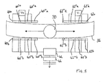
- FIG.5 A yet further embodiment of the sensor is shown in Fig.5 and again the sensor 18 in Fig.5 corresponds substantially to the sensor shown in Figs.3 and 4 and parts corresponding to parts in Figs.3 and 4 carry the same reference numbers.
- the sensor 18 in Fig.5 has a curved tube 36 rather like that shown in Fig.4 but multiple pairs of contact plates 40a,b, 40'a,b, 40"a,b and 40"'a,b and 42a,b, 42'a,b, 42"a,b, 42"'a,b, are provided at respective opposite ends of the tube.
- the ball 38 moves along the tube 36 towards one end thereof, it causes electrical connection to be made between the "a" plates and the "b" plates of respective successive pairs of contacts.
- the ball 38 will progressively create contacts between the 40"' contact pair, then the 40" contact pair, then the 40' contact pair and then finally the 40 contact pair. That provides an indication of the displacement of the ball in addition to its direction of movement.
- the exhaust damping device 16 is strapped to an exhaust pipe 10 which is itself connected to an external combustion engine of, for example, a vehicle.
- the exhaust will vibrate as a consequence of the engine vibration, vehicle motion, airflow around the exhaust and gas flow through the exhaust.
- the damping device 16 is arranged spaced from the exhaust mounts 12, 14. The intention of that positioning is that the vibration of the exhaust will have its greatest amplitude spaced from the mounting points and so the sensor 18 of the damping device 16 will pick up more vibrations at that position than closer to the exhaust mounting.
- the sensor 18 is rigidly attached to the exhaust by means of the strap 24 so that any vibrations encountered by the exhaust are transmitted to the sensor 18.
- the sensors 18 from those figures are arranged so that the tube 36 lies substantially horizontally in order to prevent the ball from rolling towards one end of the tube or the other under the simple action of gravity.
- the tube 36 moves with the exhaust.
- the ball 38 has a relatively high inertial mass compared with the frictional force holding the ball in position in the tube, movement of the tube in space will cause relative movement of the ball 38 along the tube 36 in the opposite direction to the movement of the tube. Consequently, movement of the exhaust results in a corresponding movement of the ball along the tube in the opposite direction to the movement of the exhaust if the tube is taken as the frame of reference.
- Movement of the exhaust having sufficient amplitude will cause the ball 38 to move into contact with the contact plates 40a, 40b or 42a, 42b at one of the ends of the tube. That contact creates a signal indicative of the end of the tube which the ball has contacted, generated in signal generator 44 and the signal is transmitted via a resistor 46 to a control unit 20 which includes a microprocessor. On receipt of such a signal, the microprocessor 20 sends a control signal to the stepper motor 26 which drives the eccentric mass 28 reciprocally against end stops 30, 32. Under most conditions, the movement of the exhaust will be oscillatory which will, in turn, result in an oscillatory movement of the ball 38 in the tube, resulting in alternate positive and negative signals being generated by the signal generator 44.
- the microprocessor control 20 will drive the stepper motor 26 in an oscillatory fashion.
- the stepper motor is intended to drive the mass against the end stops 30, 32 and, in doing so, when the mass 28 strikes one of the end stops 30, 32 an impulsive force is generated generally in the direction of travel of the mass 28.
- the mass is driven in phase of the movement of the ball 38 which, in view of the arrangement of the ball in tube sensor on the exhaust, is 180 degrees out of phase with the movement of the exhaust pipe 10.
- An example of the movement of the exhaust, the ball and the driving of the mass is shown in Fig.6. In that figure a graph is shown illustrating the movement of various parts over time.
- the first sinusoidal track, marked 48, illustrates the movement of the exhaust pipe 10 while the second sinusoidal track 50 represents the movement of the ball 38 in the tube 36. That results in an electrical signal generated by the signal generator 44 shown by virtue of the line 52 in Fig.6.
- the control unit 20 then causes the stepper motor 26 to drive the mass 28 reciprocally and the motion of the mass 28 is represented by the line 54 in Fig.6.
- the forces generated by the mass 28 moving out of phase with the vibrating exhaust 10 tends to damp the movement of the exhaust 10.
- the forces generated by the moving mass 28 striking ends 30, 32 are acting out of phase with the forces driving the exhaust pipe 10. That, in turn, reduces the overall net force in the system which thus reduces the vibrations of the exhaust 10.
- the mass 28 is driven rather more impulsively than the sinusoidal driving of the mass illustrated in Fig.6.
- Fig.7 it can be seen that the exhaust 10 is vibrating as in Fig.6 (as illustrated by the line 48), as is the ball 38 in tube 36 (as illustrated by the line 50). Again, a similar signal pattern is illustrated in Fig.7 (as shown by the line 52) but the mass is driven impulsively so as to create a substantial force acting opposite to the force driving the exhaust.
- the line 56 illustrates the driving of the mass 28 by the stepper motor 26. Although the force generated by such driving of the mass is "spiky" there is still a substantial damping effect created by the input of force in this way. The force is input out of phase with the forces causing the vibration. In both of the systems shown in Fig.6 and Fig.7, the intention is to remove energy from the vibrating system which is done by countering the forces creating the vibration directly with force acting in the opposite direction.
- the advantage of the present invention is that the damping force generated by movement of the mass by the stepper motor 26 is targeted directly at the movement of the exhaust throughout the frequency range of vibrations that the exhaust is subjected to.
Landscapes
- Engineering & Computer Science (AREA)
- General Engineering & Computer Science (AREA)
- Chemical & Material Sciences (AREA)
- Mechanical Engineering (AREA)
- Combustion & Propulsion (AREA)
- Analytical Chemistry (AREA)
- Exhaust Silencers (AREA)
- Vibration Prevention Devices (AREA)
Applications Claiming Priority (2)
| Application Number | Priority Date | Filing Date | Title |
|---|---|---|---|
| GB0311386A GB2401922A (en) | 2003-05-17 | 2003-05-17 | An engine exhaust damping device |
| GB0311386 | 2003-05-17 |
Publications (2)
| Publication Number | Publication Date |
|---|---|
| EP1479937A2 true EP1479937A2 (fr) | 2004-11-24 |
| EP1479937A3 EP1479937A3 (fr) | 2005-04-20 |
Family
ID=9958280
Family Applications (1)
| Application Number | Title | Priority Date | Filing Date |
|---|---|---|---|
| EP04252148A Withdrawn EP1479937A3 (fr) | 2003-05-17 | 2004-04-13 | Dispositif d'amortissement de gaz d'échappement de moteurs |
Country Status (2)
| Country | Link |
|---|---|
| EP (1) | EP1479937A3 (fr) |
| GB (1) | GB2401922A (fr) |
Citations (1)
| Publication number | Priority date | Publication date | Assignee | Title |
|---|---|---|---|---|
| GB2228778A (en) | 1989-01-28 | 1990-09-05 | Continental Ag | A motor vehicle engine mounting |
Family Cites Families (7)
| Publication number | Priority date | Publication date | Assignee | Title |
|---|---|---|---|---|
| CH495515A (de) * | 1968-08-30 | 1970-08-31 | Sulzer Ag | Dämpfer für Körper, die in drei verschiedenen Achsrichtungen schwingen können |
| JPS60173306A (ja) * | 1984-02-20 | 1985-09-06 | Mazda Motor Corp | 自動車の振動減衰装置 |
| FR2674594B1 (fr) * | 1991-03-28 | 1993-06-04 | Acb | Dispositif pour compenser une force vibratoire ou un couple vibratoire subi par un corps. |
| FR2730288B1 (fr) * | 1995-02-03 | 1997-04-18 | Mesure Et Inf Mei | Dispositifs de reduction de vibrations a commande active constitues de masses mobiles excitees par des electro aimants selon 2 ou 3 axes |
| US5713438A (en) * | 1996-03-25 | 1998-02-03 | Lord Corporation | Method and apparatus for non-model based decentralized adaptive feedforward active vibration control |
| US5802184A (en) * | 1996-08-15 | 1998-09-01 | Lord Corporation | Active noise and vibration control system |
| JPH11247919A (ja) * | 1998-03-04 | 1999-09-14 | Tokai Rubber Ind Ltd | 流体封入式能動型防振装置 |
-
2003
- 2003-05-17 GB GB0311386A patent/GB2401922A/en not_active Withdrawn
-
2004
- 2004-04-13 EP EP04252148A patent/EP1479937A3/fr not_active Withdrawn
Patent Citations (1)
| Publication number | Priority date | Publication date | Assignee | Title |
|---|---|---|---|---|
| GB2228778A (en) | 1989-01-28 | 1990-09-05 | Continental Ag | A motor vehicle engine mounting |
Also Published As
| Publication number | Publication date |
|---|---|
| GB2401922A (en) | 2004-11-24 |
| EP1479937A3 (fr) | 2005-04-20 |
| GB0311386D0 (en) | 2003-06-25 |
Similar Documents
| Publication | Publication Date | Title |
|---|---|---|
| CN103278147B (zh) | 惯性力传感器 | |
| SU1194288A3 (ru) | Вибромолот | |
| US10795485B2 (en) | Touch-sensitive input device with improved haptic generation | |
| CN113272573A (zh) | 自适应调谐吸振器 | |
| JP2003148569A (ja) | 動力伝達用チェーンおよびテンショナシステム | |
| KR970022627A (ko) | 진동 구조물 및 진동 구조물의 고유 진동수 제어 방법 | |
| KR970702474A (ko) | 진동식 자이로 마이크로머신의 진동자(A micromachine oscillator for oscillogyrometer) | |
| KR100979319B1 (ko) | 진동식 반송장치 | |
| JPH037816B2 (fr) | ||
| EP1479937A2 (fr) | Dispositif d'amortissement de gaz d'échappement de moteurs | |
| JP2001509577A (ja) | アッセンブリ支持装置の制御方法 | |
| JP2007256235A (ja) | 慣性力センサ | |
| JP2001234972A (ja) | 制振ユニット及び制振装置 | |
| JPH07168631A (ja) | 振動制振装置 | |
| KR101316834B1 (ko) | 동흡진 장치 | |
| WO2004099647A1 (fr) | Appareil actif anti-vibrations et vehicule equipe de cet appareil anti-vibrations | |
| KR200371089Y1 (ko) | 댐퍼유니트 | |
| JPH0781514A (ja) | 衝突検知装置 | |
| KR19990030562U (ko) | 차량의 엔진 마운팅 구조 | |
| US3369248A (en) | Recording pendulum with plural drive means | |
| JPH0326411Y2 (fr) | ||
| JPWO2017130919A1 (ja) | サスペンション | |
| KR100193505B1 (ko) | 전자기를 이용한 진동 흡진기 | |
| SU1035315A1 (ru) | Устройство дл уменьшени колебаний объекта | |
| JPS6332323Y2 (fr) |
Legal Events
| Date | Code | Title | Description |
|---|---|---|---|
| PUAI | Public reference made under article 153(3) epc to a published international application that has entered the european phase |
Free format text: ORIGINAL CODE: 0009012 |
|
| AK | Designated contracting states |
Kind code of ref document: A2 Designated state(s): AT BE BG CH CY CZ DE DK EE ES FI FR GB GR HU IE IT LI LU MC NL PL PT RO SE SI SK TR |
|
| AX | Request for extension of the european patent |
Extension state: AL HR LT LV MK |
|
| PUAL | Search report despatched |
Free format text: ORIGINAL CODE: 0009013 |
|
| AK | Designated contracting states |
Kind code of ref document: A3 Designated state(s): AT BE BG CH CY CZ DE DK EE ES FI FR GB GR HU IE IT LI LU MC NL PL PT RO SE SI SK TR |
|
| AX | Request for extension of the european patent |
Extension state: AL HR LT LV MK |
|
| AKX | Designation fees paid | ||
| REG | Reference to a national code |
Ref country code: DE Ref legal event code: 8566 |
|
| STAA | Information on the status of an ep patent application or granted ep patent |
Free format text: STATUS: THE APPLICATION IS DEEMED TO BE WITHDRAWN |
|
| 18D | Application deemed to be withdrawn |
Effective date: 20051021 |