EP1479954A2 - Outil poussant-coupant oléodynamique - Google Patents
Outil poussant-coupant oléodynamique Download PDFInfo
- Publication number
- EP1479954A2 EP1479954A2 EP04010652A EP04010652A EP1479954A2 EP 1479954 A2 EP1479954 A2 EP 1479954A2 EP 04010652 A EP04010652 A EP 04010652A EP 04010652 A EP04010652 A EP 04010652A EP 1479954 A2 EP1479954 A2 EP 1479954A2
- Authority
- EP
- European Patent Office
- Prior art keywords
- handle
- shells
- oil
- pivotable
- pivotable handle
- Prior art date
- Legal status (The legal status is an assumption and is not a legal conclusion. Google has not performed a legal analysis and makes no representation as to the accuracy of the status listed.)
- Granted
Links
Images


Classifications
-
- B—PERFORMING OPERATIONS; TRANSPORTING
- B23—MACHINE TOOLS; METAL-WORKING NOT OTHERWISE PROVIDED FOR
- B23D—PLANING; SLOTTING; SHEARING; BROACHING; SAWING; FILING; SCRAPING; LIKE OPERATIONS FOR WORKING METAL BY REMOVING MATERIAL, NOT OTHERWISE PROVIDED FOR
- B23D29/00—Hand-held metal-shearing or metal-cutting devices
- B23D29/002—Hand-held metal-shearing or metal-cutting devices for cutting wire or the like
-
- B—PERFORMING OPERATIONS; TRANSPORTING
- B23—MACHINE TOOLS; METAL-WORKING NOT OTHERWISE PROVIDED FOR
- B23D—PLANING; SLOTTING; SHEARING; BROACHING; SAWING; FILING; SCRAPING; LIKE OPERATIONS FOR WORKING METAL BY REMOVING MATERIAL, NOT OTHERWISE PROVIDED FOR
- B23D15/00—Shearing machines or shearing devices cutting by blades which move parallel to themselves
- B23D15/12—Shearing machines or shearing devices cutting by blades which move parallel to themselves characterised by drives or gearings therefor
- B23D15/14—Shearing machines or shearing devices cutting by blades which move parallel to themselves characterised by drives or gearings therefor actuated by fluid or gas pressure
-
- B—PERFORMING OPERATIONS; TRANSPORTING
- B25—HAND TOOLS; PORTABLE POWER-DRIVEN TOOLS; MANIPULATORS
- B25B—TOOLS OR BENCH DEVICES NOT OTHERWISE PROVIDED FOR, FOR FASTENING, CONNECTING, DISENGAGING, OR HOLDING
- B25B27/00—Hand tools, specially adapted for fitting together or separating parts or objects whether or not involving some deformation, not otherwise provided for
- B25B27/14—Hand tools, specially adapted for fitting together or separating parts or objects whether or not involving some deformation, not otherwise provided for for assembling objects other than by press fit or detaching same
- B25B27/146—Clip clamping hand tools
-
- F—MECHANICAL ENGINEERING; LIGHTING; HEATING; WEAPONS; BLASTING
- F16—ENGINEERING ELEMENTS AND UNITS; GENERAL MEASURES FOR PRODUCING AND MAINTAINING EFFECTIVE FUNCTIONING OF MACHINES OR INSTALLATIONS; THERMAL INSULATION IN GENERAL
- F16K—VALVES; TAPS; COCKS; ACTUATING-FLOATS; DEVICES FOR VENTING OR AERATING
- F16K15/00—Check valves
- F16K15/18—Check valves with actuating mechanism; Combined check valves and actuated valves
- F16K15/182—Check valves with actuating mechanism; Combined check valves and actuated valves with actuating mechanism
- F16K15/1823—Check valves with actuating mechanism; Combined check valves and actuated valves with actuating mechanism for ball check valves
-
- H—ELECTRICITY
- H01—ELECTRIC ELEMENTS
- H01R—ELECTRICALLY-CONDUCTIVE CONNECTIONS; STRUCTURAL ASSOCIATIONS OF A PLURALITY OF MUTUALLY-INSULATED ELECTRICAL CONNECTING ELEMENTS; COUPLING DEVICES; CURRENT COLLECTORS
- H01R43/00—Apparatus or processes specially adapted for manufacturing, assembling, maintaining, or repairing of line connectors or current collectors or for joining electric conductors
- H01R43/04—Apparatus or processes specially adapted for manufacturing, assembling, maintaining, or repairing of line connectors or current collectors or for joining electric conductors for forming connections by deformation, e.g. crimping tool
- H01R43/042—Hand tools for crimping
- H01R43/0427—Hand tools for crimping fluid actuated hand crimping tools
Definitions
- the known oleodynamic tools consist essentially of a pump body which is fixedly connected to a handle, from a second handle for the actuation of the pump which is pivotally mounted on the same pump body and a front approach to the pump body for the use of replaceable printing or cutting heads.
- the tools must be provided with a drain valve to allow, as a result of the execution of a pressure or cutting operation, the opening of the tool and further comprise a locking mechanism to prevent the spreading of the movable handle by the action of acting on the pump piston return spring.
- the actuation of the drain valve via a small lever provided on the pivotable handle or on the pump body lever, this acts on a stop element which actuates the exhaust valve on complete closing of the lever.
- This system has the disadvantage that in order to actuate the drain valve further actuation of the handle is necessary, which causes further undesirable compression. It is also an operation of the drain valve by turning the oil tank equipped and articulated on the pump body handle known. This solution brings a cumbersome handling with it because of the handle in question, the entire weight of the tool is worn, further, the operation, in the case of high working pressure, not convenient why this system is not usable for tools which, for example, a pressure of about 550 bar exceed; this actuating mechanism is further exposed to contamination and significant wear.
- the invention has set itself the task of an oleodynamic tool of the above mentioned type to provide a convenient operation of the drain valve in any position of the pivoting handle and locking the closed position of the pivoting handle, without the operation specific locking mechanisms, which further with only one hand It can be actuated by the fast positioning movement of the tools on the workpiece Achieving maintenance and repair friendliness and an optimal Protection against unwanted electrical contacts is offered.
- the pivotable Handle be it the operation of the drain valve, as well as the blocking of the Closed position of the handle is assigned; which, however, the protection against Regarding unwanted electrical contacts, the invention proposes the attachment of Shells of non-conductive material in front of which in the case of maintenance and / or Repair easily removable and, in case of damage, are interchangeable meeting the strictest safety standards.
- the pivotable handle on the body of the oil pump according to rotatably supported by its longitudinal axis whereby the rotation of an axial Shift is generated, with a direction of rotation is used to on the Discharge valve to act and used the other opposite direction of rotation is to act on a Einhnatureorgan.
- the Handle in any pumping position, to act on the drain valve without the continue to press applied patch or cutting tool.
- the locking of the handle in the closed position is done by turning the handle in the opposite direction thus creating a suspension element, after Taking the closed position of the handle, is brought into latching position.
- a rotatable about its longitudinal axis storage of the handle provided on the receiving element wherein at the end of the handle a rotary and Displacement element is provided which with the receiving element in Screw connection is, by turning said rotary and Displacement element is thus an axial displacement of the rotary and Displacement element itself reaches which coaxially at the end of the handle is attached.
- the front end of said rotary and Displacement element is suitable for axial feed, due Rotation of the handle e.g. to the right, to act on mechanical elements which are in contact with each other or are connected with each other and of at least one compression spring are loaded, said spring with pressure is loaded and the drain valve is opened. That at the end of the handle attached rotary and displacement element which a threaded area has acts by means of the two ends of the over the diameter of this Elementes projecting transverse pin and due to rotation in the opposite direction and thus due to displacement (retraction), on a suspension of the End, in the closed position of the handle, in a recess on Pump housing engages around the closed position of the handle close to, with the pump housing firmly connected handle to lock.
- the Blocking the closed position of the pivoting handle and the To define pumping position acts in a seat of the pivot bearing of the swivel handle a mechanism which at the turn and Displacement element is provided by means of a ball which, under effect a spring, in the individual rotational positions of the handle in dome-shaped or grooved seats on the bearing element which snaps the position of the individual corresponding actuation phases (opening the drain valve, Pumps, locks the swivel handle) correspond.
- the handles preferably made of non-conductive material
- the area of the end sections near the pump body is according to the invention with a non-conductive connecting and reinforcing sleeve provided, wherein the non-conductive sleeve on the pivotable handle for the Attachment of a handle element is used which easily with one hand together with the corresponding area of the immovable handle can be used to fast pump movements for a quick Approaching the tools to reach the connecting parts.
- This handle can be varied, bow-shaped or ring-shaped and Although closed or open, be integral with the non-conductive sleeve or on this, or directly on the handle lever, be appropriate.
- the invention concludes Furthermore, not that the inner handle element over a part or on the entire length of the handle extends or that this element of flexible Material is or is a belt or a string.
- the pump body of two lateral shells whose Margins to overlap a width set by safety standards, be covered and the front and back of a ring not conductive material are held in the assembled position.
- the frontal ring also forms a collar at the same time which the approach area the oleodynamic pressure or cutting tool heads covers during the rear ring the joined together, the front area of non-conductive Cover of immovable handle, cross-over shells, holds.
- the form two laterally attached to the pump body shells According to the invention also a part of the non-conductive cover of Lager Symposiumes the swivel handle by this the shape of a Ball cap form which of the position of the bearing pin of the pivoting Handle is determined.
- This area of the insulating cover is partially covered by a shell which at the front end of the non-conductive Sleeve of the pivoting handle is attached.
- This shell is on the side, coaxial with the axis of rotation of the pivotable handle, from the side of the Pump body attached non-conductive shells, protruding pin, snapped and held by pins which of the non-conductive sleeve the pivoting handle protrude near its storage area, thereby achieved a complete articulated coverage of the entire storage area becomes.
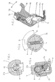
- Fig. 1 shows a side view of the inventive olden dynamic pressure and Cutting tool with closed handles.
- Fig. 2 shows the view from the left of the tool shown in Fig. 1.
- FIG 3 shows the cross section through the pump housing according to a Cutting plane through the axes of the handles, by the storage of the pivotable handle, by the actuating mechanism of the drain valve and by the locking mechanism of the pivotable handle.
- FIG. 4 is a sectional view according to the sectional plane shown in FIG. 3 IV-IV which by the suspension element of the pivoting handle in closed position runs.
- FIG. 5 is a sectional view according to the sectional plane shown in FIG. 3 V-V which by the actuating mechanism of the suspension element of the pivoting handle in the closed position.
- FIG. 6 is a sectional view according to the sectional plane shown in FIG. 3 VI-VI which is defined by the mechanism for defining the different actuation positions of the pivotable handle extends.
- Fig. 7 shows a sectional view of the detail of the joint of the non-conductive Cover which on the tool body in the area between the two Handles is mounted in a spread position.
- the oleodynamic pressure and cutting tool consists essentially of a Body 2 which from the housing 11 for a hydraulic pump and the corresponding valves 10 is formed; from lines for the flow of oil, from actuators, from a handle 3 which fixed to the housing 11th is connected and from a handle 3a which pivotally 3d on the housing 11 stored 6 is.
- the housing 11 is frontally with a neck for use various rotatable 1 a öldynamischer pressure or cutting heads 1 provided.
- the pivotable handle 3a by means of transverse pin 4f at a tubular projection 4 a of a rotating and displacing element 4 attached which is rotatably mounted 3r on a bearing element 5 which in turn pivotally mounted by means of 3 transverse bolts 6 on the housing 11 of the pump.
- the same element 4 is provided with a bolt with roller 3c at the Panning 3d on a sliding 12a pestle 12 acts which in turn the equipped with return spring 13 a piston 13 of the pump acts.
- the rotary and displacement element 4 has a bolt-shaped end face Lug 4d with conical end 4d and is rotatable 3r in a receptacle 5a on Element 5 stored.
- the bolt-shaped projection 4c is placed in a threaded part 4b on which a part with a larger diameter with transverse bore connects in which two balls 19 are added which by a Interposed spring 20 are pressed outwards, said balls 19th snap into corresponding spherical cap-shaped seats or grooves which in tubular end portion 5b provided for receiving the bearing element 5 are.
- the spherical cap or groove shaped seats define three positions the rotation 3r of the pivotable handle 3a against the bearing element 5: a middle position P for pumping, a position R for operating the Discharge valve 10 and a position B for locking the pivotable Handle 3a in the closed position.
- handles 3, 3a exclusively from not conductive material and the complete casing of the housing 11 of the Pump, along with the mounting of the swivel handle 3a and all Mechanisms for the operation of the drain valve and for the lock of the Handle 3a in the closed position, by means of laterally easily replaceable Covering shells of plastic, in ample compliance with the applicable Safety standards, above.
- On the housing 11 are according to the invention, accordingly the direction of the axis of rotation 6 of the pivotable handle 3a, two lateral Shells 14, 14 a attached, these cover themselves along the Connection area and are frontally by placing a ring 15 which also the approach of attached replaceable printing or printing Cutting tool heads 1 covering and a rear ring 16 from not attached to conductive material.
- the shells 14, 14 a form in the region of Swivel bearing 6 of the pivotable handle 3a a ball point approach 14c which is partially covered by a shell 17 which at the front End of the non-conductive sleeve 18a of the handle 3a is snapped and from is held out of this sleeve protruding pin 18 b which in corresponding holes on the shell 17 engage.
- the shell 17 has further in, corresponding to the axis of the bearing 6 of the handle 3a Range, lateral holes in which pins 14 b engage which, always in the axis of storage 6 corresponding area, laterally from the side Peel shells 14 and 14a.
- the shell 17 in the area of Approach 14c of the lateral shells 14, 14a has an area which the Approach 14c covering and that the approach 14c and also the covering of the Shell 17 a camber with center on the axis of rotation of the storage. 6 , an articulated connection between, on the housing 11 fastened, shells 14, 14a which form the projection 14c and the, on hinged handle 3a fastened, shell 17 formed.
- the invention concludes not that the hinged guide the non-conductive shell 17 am spherical cup-shaped projection 14c, 14d by means of circular arc grooves Center is located on the axis of rotation of the bearing 6 and in which appropriate Webs or projections intervene, takes place.
- the Pivoting the pivotable handle 3a an insulating cover also in the region of the joint between the two handle levers 3, 3a secure is the attached to the handle 3a non-conductive sleeve 18a with circular arc parallel grooves 18c provided within which laterally a curved element 17a is slidably inserted which is suitable for the metallic elements in Interior of the spherical cap-shaped projection 14c, 14d of the two lateral shells 14, 14a, at any position of the pivotable handle 3a, always the cover according to the safety regulations.
Landscapes
- Engineering & Computer Science (AREA)
- Mechanical Engineering (AREA)
- General Engineering & Computer Science (AREA)
- Manufacturing & Machinery (AREA)
- Details Of Reciprocating Pumps (AREA)
- Earth Drilling (AREA)
- Shearing Machines (AREA)
- Lubricants (AREA)
- Press Drives And Press Lines (AREA)
- Jigs For Machine Tools (AREA)
Applications Claiming Priority (2)
| Application Number | Priority Date | Filing Date | Title |
|---|---|---|---|
| IT000028A ITBZ20030028A1 (it) | 2003-05-19 | 2003-05-19 | Utensile oleodinamico per la compressione ed il taglio. |
| ITBZ20030028 | 2003-05-19 |
Publications (3)
| Publication Number | Publication Date |
|---|---|
| EP1479954A2 true EP1479954A2 (fr) | 2004-11-24 |
| EP1479954A3 EP1479954A3 (fr) | 2005-03-02 |
| EP1479954B1 EP1479954B1 (fr) | 2010-07-14 |
Family
ID=33042683
Family Applications (1)
| Application Number | Title | Priority Date | Filing Date |
|---|---|---|---|
| EP04010652A Expired - Lifetime EP1479954B1 (fr) | 2003-05-19 | 2004-05-05 | Outil poussant-coupant oléodynamique |
Country Status (4)
| Country | Link |
|---|---|
| EP (1) | EP1479954B1 (fr) |
| AT (1) | ATE474168T1 (fr) |
| DE (1) | DE502004011381D1 (fr) |
| IT (1) | ITBZ20030028A1 (fr) |
Cited By (1)
| Publication number | Priority date | Publication date | Assignee | Title |
|---|---|---|---|---|
| DE102005028083B4 (de) * | 2004-07-02 | 2015-07-30 | Gustav Klauke Gmbh | Pressbackenpaar für hydraulische oder elektrische Verpressgeräte, sowie Isolierabdeckung für eine Pressbacke |
Family Cites Families (14)
| Publication number | Priority date | Publication date | Assignee | Title |
|---|---|---|---|---|
| US2821877A (en) * | 1956-02-02 | 1958-02-04 | Greenlee Bros & Co | Portable hydraulic press tool |
| US2968202A (en) * | 1958-04-11 | 1961-01-17 | Amp Inc | Hydraulic crimping tool for crimping t-tap connectors |
| GB1185871A (en) * | 1967-01-18 | 1970-03-25 | Lake & Elliot Ltd | Improved Hydraulic Lifting Jack |
| US3822966A (en) * | 1972-10-26 | 1974-07-09 | Owatonna Tool Co | Hydraulic pump |
| US4151720A (en) * | 1977-12-08 | 1979-05-01 | Vanderstappen Albert W | Manually operable hydraulic actuator |
| US4136549A (en) * | 1978-01-16 | 1979-01-30 | Burndy Corporation | Electrical cable connector tool |
| JPS6233024A (ja) * | 1985-08-05 | 1987-02-13 | Izumi Seiki Seisakusho:Kk | 油圧式締付け具 |
| DE8536425U1 (de) * | 1985-12-23 | 1986-08-07 | Fa. Hermann und Karl Birkenfeld, 5630 Remscheid | Griff für Sicherheitsbandeisenschneider |
| US4893530A (en) * | 1987-03-19 | 1990-01-16 | Warheit William A | Plier-type tool |
| US4947672A (en) * | 1989-04-03 | 1990-08-14 | Burndy Corporation | Hydraulic compression tool having an improved relief and release valve |
| JP3177828B2 (ja) * | 1997-03-07 | 2001-06-18 | 株式会社泉精器製作所 | 油圧工具の圧縮ヘッド部 |
| GB2351254B (en) * | 2000-02-28 | 2001-10-03 | Wu Chin Sung | Shears |
| EP1372915A1 (fr) * | 2001-03-28 | 2004-01-02 | Felo-Werkzeugfabrik Holland-Letz Gmbh | Outil de type pince ou cisailles, et procede servant a recouvrir leurs branches de poignee en acier de gaines de poignee en plastique |
| US6564610B2 (en) * | 2001-06-18 | 2003-05-20 | Fci Usa, Inc. | Hydraulic tool having mechanical actuator with internal bypass valve |
-
2003
- 2003-05-19 IT IT000028A patent/ITBZ20030028A1/it unknown
-
2004
- 2004-05-05 EP EP04010652A patent/EP1479954B1/fr not_active Expired - Lifetime
- 2004-05-05 DE DE502004011381T patent/DE502004011381D1/de not_active Expired - Lifetime
- 2004-05-05 AT AT04010652T patent/ATE474168T1/de active
Cited By (1)
| Publication number | Priority date | Publication date | Assignee | Title |
|---|---|---|---|---|
| DE102005028083B4 (de) * | 2004-07-02 | 2015-07-30 | Gustav Klauke Gmbh | Pressbackenpaar für hydraulische oder elektrische Verpressgeräte, sowie Isolierabdeckung für eine Pressbacke |
Also Published As
| Publication number | Publication date |
|---|---|
| ATE474168T1 (de) | 2010-07-15 |
| EP1479954B1 (fr) | 2010-07-14 |
| ITBZ20030028A1 (it) | 2004-11-20 |
| EP1479954A3 (fr) | 2005-03-02 |
| DE502004011381D1 (de) | 2010-08-26 |
Similar Documents
| Publication | Publication Date | Title |
|---|---|---|
| DE10137198B4 (de) | Klemmvorrichtung | |
| DE3151079C2 (fr) | ||
| DE102009026092A1 (de) | Crimpzange | |
| DE10022373B4 (de) | Verriegelungs- und Betätigungseinheit für seitliche Auslegerverriegelung | |
| DE4310431C2 (de) | Lenkstockschalter | |
| DE202018106210U1 (de) | Poliermaschine | |
| DE2242204A1 (de) | Druckmittelbetaetigte vorrichtung | |
| DE19956703B4 (de) | Hydraulisches Lochstanzwerkzeug | |
| DE29701730U1 (de) | Kniehebelspannvorrichtung, insbesondere zur Verwendung in Vorrichtungen und Schweißmaschinen des Karosseriebaus der Kfz-Industrie | |
| DE102008014488B4 (de) | Türschloss mit ein- und auskoppelbarer Handhabe | |
| EP1479954B1 (fr) | Outil poussant-coupant oléodynamique | |
| DE6605839U (de) | Vorrichtung zur umwandlung einer geradlinigen bewegung in eine drehbewegung | |
| EP2436844A1 (fr) | Agencement d'un palier | |
| EP3299545B1 (fr) | Boîte à ressort pourvue de bielle de commande | |
| EP0928664A2 (fr) | Dispositif à genouillère actionné à main | |
| DE10102327C1 (de) | Schwenkvorrichtung | |
| DE10328778B4 (de) | Handzange zum zentrischen Verpressen von Werkstücken | |
| EP4209685A1 (fr) | Dispositif de verrouillage | |
| DE3917828C1 (en) | Hydraulic socket spanner with revolving ring - has piston linked to piston rod connected to ratchet | |
| DE10027714B4 (de) | Betätigungsvorrichtung für Schalter zur Umpolung hoher elektrischer Gleichströme | |
| DE2404107C3 (de) | Schweißgerät zum Kaltpreßschweißen zweier Werkstücke | |
| DE102005017060B3 (de) | Kniehebelmechanismus | |
| DE10217266A1 (de) | Preßzange zum Verpressen von Hohlkörpern | |
| DE102022112087A1 (de) | Hydrauliksystem und Verfahren zum Betreiben eines Hydrauliksystems | |
| DE19935939C2 (de) | Zusatzhandgriff für Elektrowerkzeugmaschinen mit einer Sprüheinrichtung |
Legal Events
| Date | Code | Title | Description |
|---|---|---|---|
| PUAI | Public reference made under article 153(3) epc to a published international application that has entered the european phase |
Free format text: ORIGINAL CODE: 0009012 |
|
| AK | Designated contracting states |
Kind code of ref document: A2 Designated state(s): AT BE BG CH CY CZ DE DK EE ES FI FR GB GR HU IE IT LI LU MC NL PL PT RO SE SI SK TR |
|
| AX | Request for extension of the european patent |
Extension state: AL HR LT LV MK |
|
| PUAL | Search report despatched |
Free format text: ORIGINAL CODE: 0009013 |
|
| AK | Designated contracting states |
Kind code of ref document: A3 Designated state(s): AT BE BG CH CY CZ DE DK EE ES FI FR GB GR HU IE IT LI LU MC NL PL PT RO SE SI SK TR |
|
| AX | Request for extension of the european patent |
Extension state: AL HR LT LV MK |
|
| 17P | Request for examination filed |
Effective date: 20050825 |
|
| AKX | Designation fees paid |
Designated state(s): AT BE BG CH CY CZ DE DK EE ES FI FR GB GR HU IE IT LI LU MC NL PL PT RO SE SI SK TR |
|
| 17Q | First examination report despatched |
Effective date: 20070820 |
|
| GRAP | Despatch of communication of intention to grant a patent |
Free format text: ORIGINAL CODE: EPIDOSNIGR1 |
|
| RAP1 | Party data changed (applicant data changed or rights of an application transferred) |
Owner name: INTERCABLE SRL |
|
| GRAS | Grant fee paid |
Free format text: ORIGINAL CODE: EPIDOSNIGR3 |
|
| GRAA | (expected) grant |
Free format text: ORIGINAL CODE: 0009210 |
|
| AK | Designated contracting states |
Kind code of ref document: B1 Designated state(s): AT BE BG CH CY CZ DE DK EE ES FI FR GB GR HU IE IT LI LU MC NL PL PT RO SE SI SK TR |
|
| REG | Reference to a national code |
Ref country code: GB Ref legal event code: FG4D Free format text: NOT ENGLISH |
|
| REG | Reference to a national code |
Ref country code: CH Ref legal event code: EP |
|
| REG | Reference to a national code |
Ref country code: IE Ref legal event code: FG4D |
|
| REF | Corresponds to: |
Ref document number: 502004011381 Country of ref document: DE Date of ref document: 20100826 Kind code of ref document: P |
|
| REG | Reference to a national code |
Ref country code: NL Ref legal event code: VDEP Effective date: 20100714 |
|
| PG25 | Lapsed in a contracting state [announced via postgrant information from national office to epo] |
Ref country code: NL Free format text: LAPSE BECAUSE OF FAILURE TO SUBMIT A TRANSLATION OF THE DESCRIPTION OR TO PAY THE FEE WITHIN THE PRESCRIBED TIME-LIMIT Effective date: 20100714 Ref country code: FI Free format text: LAPSE BECAUSE OF FAILURE TO SUBMIT A TRANSLATION OF THE DESCRIPTION OR TO PAY THE FEE WITHIN THE PRESCRIBED TIME-LIMIT Effective date: 20100714 |
|
| REG | Reference to a national code |
Ref country code: IE Ref legal event code: FD4D |
|
| PG25 | Lapsed in a contracting state [announced via postgrant information from national office to epo] |
Ref country code: PT Free format text: LAPSE BECAUSE OF FAILURE TO SUBMIT A TRANSLATION OF THE DESCRIPTION OR TO PAY THE FEE WITHIN THE PRESCRIBED TIME-LIMIT Effective date: 20101115 Ref country code: BG Free format text: LAPSE BECAUSE OF FAILURE TO SUBMIT A TRANSLATION OF THE DESCRIPTION OR TO PAY THE FEE WITHIN THE PRESCRIBED TIME-LIMIT Effective date: 20101014 Ref country code: SI Free format text: LAPSE BECAUSE OF FAILURE TO SUBMIT A TRANSLATION OF THE DESCRIPTION OR TO PAY THE FEE WITHIN THE PRESCRIBED TIME-LIMIT Effective date: 20100714 Ref country code: PL Free format text: LAPSE BECAUSE OF FAILURE TO SUBMIT A TRANSLATION OF THE DESCRIPTION OR TO PAY THE FEE WITHIN THE PRESCRIBED TIME-LIMIT Effective date: 20100714 Ref country code: CY Free format text: LAPSE BECAUSE OF FAILURE TO SUBMIT A TRANSLATION OF THE DESCRIPTION OR TO PAY THE FEE WITHIN THE PRESCRIBED TIME-LIMIT Effective date: 20100714 |
|
| PG25 | Lapsed in a contracting state [announced via postgrant information from national office to epo] |
Ref country code: SE Free format text: LAPSE BECAUSE OF FAILURE TO SUBMIT A TRANSLATION OF THE DESCRIPTION OR TO PAY THE FEE WITHIN THE PRESCRIBED TIME-LIMIT Effective date: 20100714 Ref country code: GR Free format text: LAPSE BECAUSE OF FAILURE TO SUBMIT A TRANSLATION OF THE DESCRIPTION OR TO PAY THE FEE WITHIN THE PRESCRIBED TIME-LIMIT Effective date: 20101015 |
|
| PG25 | Lapsed in a contracting state [announced via postgrant information from national office to epo] |
Ref country code: DK Free format text: LAPSE BECAUSE OF FAILURE TO SUBMIT A TRANSLATION OF THE DESCRIPTION OR TO PAY THE FEE WITHIN THE PRESCRIBED TIME-LIMIT Effective date: 20100714 Ref country code: IE Free format text: LAPSE BECAUSE OF FAILURE TO SUBMIT A TRANSLATION OF THE DESCRIPTION OR TO PAY THE FEE WITHIN THE PRESCRIBED TIME-LIMIT Effective date: 20100714 |
|
| PLBE | No opposition filed within time limit |
Free format text: ORIGINAL CODE: 0009261 |
|
| STAA | Information on the status of an ep patent application or granted ep patent |
Free format text: STATUS: NO OPPOSITION FILED WITHIN TIME LIMIT |
|
| PG25 | Lapsed in a contracting state [announced via postgrant information from national office to epo] |
Ref country code: RO Free format text: LAPSE BECAUSE OF FAILURE TO SUBMIT A TRANSLATION OF THE DESCRIPTION OR TO PAY THE FEE WITHIN THE PRESCRIBED TIME-LIMIT Effective date: 20100714 Ref country code: SK Free format text: LAPSE BECAUSE OF FAILURE TO SUBMIT A TRANSLATION OF THE DESCRIPTION OR TO PAY THE FEE WITHIN THE PRESCRIBED TIME-LIMIT Effective date: 20100714 Ref country code: CZ Free format text: LAPSE BECAUSE OF FAILURE TO SUBMIT A TRANSLATION OF THE DESCRIPTION OR TO PAY THE FEE WITHIN THE PRESCRIBED TIME-LIMIT Effective date: 20100714 Ref country code: EE Free format text: LAPSE BECAUSE OF FAILURE TO SUBMIT A TRANSLATION OF THE DESCRIPTION OR TO PAY THE FEE WITHIN THE PRESCRIBED TIME-LIMIT Effective date: 20100714 |
|
| 26N | No opposition filed |
Effective date: 20110415 |
|
| PG25 | Lapsed in a contracting state [announced via postgrant information from national office to epo] |
Ref country code: ES Free format text: LAPSE BECAUSE OF FAILURE TO SUBMIT A TRANSLATION OF THE DESCRIPTION OR TO PAY THE FEE WITHIN THE PRESCRIBED TIME-LIMIT Effective date: 20101025 |
|
| REG | Reference to a national code |
Ref country code: DE Ref legal event code: R097 Ref document number: 502004011381 Country of ref document: DE Effective date: 20110415 |
|
| BERE | Be: lapsed |
Owner name: INTERCABLE SRL Effective date: 20110531 |
|
| PG25 | Lapsed in a contracting state [announced via postgrant information from national office to epo] |
Ref country code: MC Free format text: LAPSE BECAUSE OF NON-PAYMENT OF DUE FEES Effective date: 20110531 |
|
| REG | Reference to a national code |
Ref country code: CH Ref legal event code: PL |
|
| PG25 | Lapsed in a contracting state [announced via postgrant information from national office to epo] |
Ref country code: LI Free format text: LAPSE BECAUSE OF NON-PAYMENT OF DUE FEES Effective date: 20110531 Ref country code: CH Free format text: LAPSE BECAUSE OF NON-PAYMENT OF DUE FEES Effective date: 20110531 |
|
| PG25 | Lapsed in a contracting state [announced via postgrant information from national office to epo] |
Ref country code: BE Free format text: LAPSE BECAUSE OF NON-PAYMENT OF DUE FEES Effective date: 20110531 |
|
| REG | Reference to a national code |
Ref country code: AT Ref legal event code: MM01 Ref document number: 474168 Country of ref document: AT Kind code of ref document: T Effective date: 20110505 |
|
| PG25 | Lapsed in a contracting state [announced via postgrant information from national office to epo] |
Ref country code: AT Free format text: LAPSE BECAUSE OF NON-PAYMENT OF DUE FEES Effective date: 20110505 |
|
| PG25 | Lapsed in a contracting state [announced via postgrant information from national office to epo] |
Ref country code: LU Free format text: LAPSE BECAUSE OF NON-PAYMENT OF DUE FEES Effective date: 20110505 |
|
| PG25 | Lapsed in a contracting state [announced via postgrant information from national office to epo] |
Ref country code: TR Free format text: LAPSE BECAUSE OF FAILURE TO SUBMIT A TRANSLATION OF THE DESCRIPTION OR TO PAY THE FEE WITHIN THE PRESCRIBED TIME-LIMIT Effective date: 20100714 |
|
| PG25 | Lapsed in a contracting state [announced via postgrant information from national office to epo] |
Ref country code: HU Free format text: LAPSE BECAUSE OF FAILURE TO SUBMIT A TRANSLATION OF THE DESCRIPTION OR TO PAY THE FEE WITHIN THE PRESCRIBED TIME-LIMIT Effective date: 20100714 |
|
| REG | Reference to a national code |
Ref country code: FR Ref legal event code: PLFP Year of fee payment: 12 |
|
| REG | Reference to a national code |
Ref country code: FR Ref legal event code: PLFP Year of fee payment: 13 |
|
| REG | Reference to a national code |
Ref country code: FR Ref legal event code: PLFP Year of fee payment: 14 |
|
| REG | Reference to a national code |
Ref country code: FR Ref legal event code: PLFP Year of fee payment: 15 |
|
| PGFP | Annual fee paid to national office [announced via postgrant information from national office to epo] |
Ref country code: IT Payment date: 20230525 Year of fee payment: 20 Ref country code: FR Payment date: 20230531 Year of fee payment: 20 Ref country code: DE Payment date: 20230524 Year of fee payment: 20 |
|
| PGFP | Annual fee paid to national office [announced via postgrant information from national office to epo] |
Ref country code: GB Payment date: 20230518 Year of fee payment: 20 |
|
| REG | Reference to a national code |
Ref country code: DE Ref legal event code: R071 Ref document number: 502004011381 Country of ref document: DE |
|
| REG | Reference to a national code |
Ref country code: GB Ref legal event code: PE20 Expiry date: 20240504 |
|
| PG25 | Lapsed in a contracting state [announced via postgrant information from national office to epo] |
Ref country code: GB Free format text: LAPSE BECAUSE OF EXPIRATION OF PROTECTION Effective date: 20240504 |
|
| PG25 | Lapsed in a contracting state [announced via postgrant information from national office to epo] |
Ref country code: GB Free format text: LAPSE BECAUSE OF EXPIRATION OF PROTECTION Effective date: 20240504 |