EP1480073B1 - Feuille d'affichage d'image mince reinscriptible, affichage d'image et procede d'affichage d'image - Google Patents
Feuille d'affichage d'image mince reinscriptible, affichage d'image et procede d'affichage d'image Download PDFInfo
- Publication number
- EP1480073B1 EP1480073B1 EP03703133A EP03703133A EP1480073B1 EP 1480073 B1 EP1480073 B1 EP 1480073B1 EP 03703133 A EP03703133 A EP 03703133A EP 03703133 A EP03703133 A EP 03703133A EP 1480073 B1 EP1480073 B1 EP 1480073B1
- Authority
- EP
- European Patent Office
- Prior art keywords
- image display
- layer
- transparent layer
- display sheet
- magnetic powder
- Prior art date
- Legal status (The legal status is an assumption and is not a legal conclusion. Google has not performed a legal analysis and makes no representation as to the accuracy of the status listed.)
- Expired - Lifetime
Links
- 238000000034 method Methods 0.000 title claims description 28
- 239000006247 magnetic powder Substances 0.000 claims abstract description 101
- 239000010410 layer Substances 0.000 claims description 270
- 238000002844 melting Methods 0.000 claims description 61
- 239000000463 material Substances 0.000 claims description 42
- 239000012071 phase Substances 0.000 claims description 35
- 238000001816 cooling Methods 0.000 claims description 29
- 238000010438 heat treatment Methods 0.000 claims description 27
- 238000006073 displacement reaction Methods 0.000 claims description 26
- 239000002245 particle Substances 0.000 claims description 25
- 230000008018 melting Effects 0.000 claims description 24
- 229910000859 α-Fe Inorganic materials 0.000 claims description 19
- 125000006850 spacer group Chemical group 0.000 claims description 18
- 229920005989 resin Polymers 0.000 claims description 16
- 239000011347 resin Substances 0.000 claims description 16
- OKTJSMMVPCPJKN-UHFFFAOYSA-N Carbon Chemical compound [C] OKTJSMMVPCPJKN-UHFFFAOYSA-N 0.000 claims description 15
- 239000011247 coating layer Substances 0.000 claims description 15
- 229910052799 carbon Inorganic materials 0.000 claims description 13
- 230000008569 process Effects 0.000 claims description 11
- PXHVJJICTQNCMI-UHFFFAOYSA-N Nickel Chemical compound [Ni] PXHVJJICTQNCMI-UHFFFAOYSA-N 0.000 claims description 8
- 239000000843 powder Substances 0.000 claims description 8
- 239000011324 bead Substances 0.000 claims description 7
- 230000008859 change Effects 0.000 claims description 7
- 239000011230 binding agent Substances 0.000 claims description 5
- 239000007791 liquid phase Substances 0.000 claims description 5
- 230000004044 response Effects 0.000 claims description 5
- 229920003002 synthetic resin Polymers 0.000 claims description 5
- 239000000057 synthetic resin Substances 0.000 claims description 5
- 229910052759 nickel Inorganic materials 0.000 claims description 4
- 239000007787 solid Substances 0.000 claims description 4
- 238000005187 foaming Methods 0.000 claims description 3
- 229910052751 metal Inorganic materials 0.000 claims description 3
- 239000002184 metal Substances 0.000 claims description 3
- 239000002105 nanoparticle Substances 0.000 claims description 3
- 239000007790 solid phase Substances 0.000 claims description 3
- 230000001360 synchronised effect Effects 0.000 claims description 3
- 230000020169 heat generation Effects 0.000 abstract description 30
- 239000001993 wax Substances 0.000 description 41
- 230000004048 modification Effects 0.000 description 35
- 238000012986 modification Methods 0.000 description 35
- 230000007246 mechanism Effects 0.000 description 9
- UQSXHKLRYXJYBZ-UHFFFAOYSA-N Iron oxide Chemical compound [Fe]=O UQSXHKLRYXJYBZ-UHFFFAOYSA-N 0.000 description 6
- 239000003094 microcapsule Substances 0.000 description 6
- -1 Polyethylene Terephthalate Polymers 0.000 description 5
- 238000004040 coloring Methods 0.000 description 5
- 239000011521 glass Substances 0.000 description 5
- 239000012188 paraffin wax Substances 0.000 description 5
- 229920000139 polyethylene terephthalate Polymers 0.000 description 5
- 239000005020 polyethylene terephthalate Substances 0.000 description 5
- 239000003208 petroleum Substances 0.000 description 4
- 229920002050 silicone resin Polymers 0.000 description 4
- 244000241463 Cullen corylifolium Species 0.000 description 3
- 238000009500 colour coating Methods 0.000 description 3
- 230000005484 gravity Effects 0.000 description 3
- 229920001721 polyimide Polymers 0.000 description 3
- 239000012463 white pigment Substances 0.000 description 3
- MYRTYDVEIRVNKP-UHFFFAOYSA-N 1,2-Divinylbenzene Chemical compound C=CC1=CC=CC=C1C=C MYRTYDVEIRVNKP-UHFFFAOYSA-N 0.000 description 2
- OEPOKWHJYJXUGD-UHFFFAOYSA-N 2-(3-phenylmethoxyphenyl)-1,3-thiazole-4-carbaldehyde Chemical compound O=CC1=CSC(C=2C=C(OCC=3C=CC=CC=3)C=CC=2)=N1 OEPOKWHJYJXUGD-UHFFFAOYSA-N 0.000 description 2
- VTYYLEPIZMXCLO-UHFFFAOYSA-L Calcium carbonate Chemical compound [Ca+2].[O-]C([O-])=O VTYYLEPIZMXCLO-UHFFFAOYSA-L 0.000 description 2
- VYPSYNLAJGMNEJ-UHFFFAOYSA-N Silicium dioxide Chemical compound O=[Si]=O VYPSYNLAJGMNEJ-UHFFFAOYSA-N 0.000 description 2
- 229910021393 carbon nanotube Inorganic materials 0.000 description 2
- 239000002041 carbon nanotube Substances 0.000 description 2
- 239000012141 concentrate Substances 0.000 description 2
- 239000000499 gel Substances 0.000 description 2
- 239000007788 liquid Substances 0.000 description 2
- 239000006249 magnetic particle Substances 0.000 description 2
- 239000000203 mixture Substances 0.000 description 2
- 229920001343 polytetrafluoroethylene Polymers 0.000 description 2
- 239000004810 polytetrafluoroethylene Substances 0.000 description 2
- 239000004065 semiconductor Substances 0.000 description 2
- 238000011144 upstream manufacturing Methods 0.000 description 2
- 229920000178 Acrylic resin Polymers 0.000 description 1
- 239000004925 Acrylic resin Substances 0.000 description 1
- 229920001817 Agar Polymers 0.000 description 1
- XMWRBQBLMFGWIX-UHFFFAOYSA-N C60 fullerene Chemical compound C12=C3C(C4=C56)=C7C8=C5C5=C9C%10=C6C6=C4C1=C1C4=C6C6=C%10C%10=C9C9=C%11C5=C8C5=C8C7=C3C3=C7C2=C1C1=C2C4=C6C4=C%10C6=C9C9=C%11C5=C5C8=C3C3=C7C1=C1C2=C4C6=C2C9=C5C3=C12 XMWRBQBLMFGWIX-UHFFFAOYSA-N 0.000 description 1
- 108010010803 Gelatin Proteins 0.000 description 1
- PEDCQBHIVMGVHV-UHFFFAOYSA-N Glycerol Natural products OCC(O)CO PEDCQBHIVMGVHV-UHFFFAOYSA-N 0.000 description 1
- XEEYBQQBJWHFJM-UHFFFAOYSA-N Iron Chemical compound [Fe] XEEYBQQBJWHFJM-UHFFFAOYSA-N 0.000 description 1
- 239000004642 Polyimide Substances 0.000 description 1
- SMEGJBVQLJJKKX-HOTMZDKISA-N [(2R,3S,4S,5R,6R)-5-acetyloxy-3,4,6-trihydroxyoxan-2-yl]methyl acetate Chemical compound CC(=O)OC[C@@H]1[C@H]([C@@H]([C@H]([C@@H](O1)O)OC(=O)C)O)O SMEGJBVQLJJKKX-HOTMZDKISA-N 0.000 description 1
- 229940081735 acetylcellulose Drugs 0.000 description 1
- 239000000853 adhesive Substances 0.000 description 1
- 230000001070 adhesive effect Effects 0.000 description 1
- 239000008272 agar Substances 0.000 description 1
- WNROFYMDJYEPJX-UHFFFAOYSA-K aluminium hydroxide Chemical compound [OH-].[OH-].[OH-].[Al+3] WNROFYMDJYEPJX-UHFFFAOYSA-K 0.000 description 1
- PNEYBMLMFCGWSK-UHFFFAOYSA-N aluminium oxide Inorganic materials [O-2].[O-2].[O-2].[Al+3].[Al+3] PNEYBMLMFCGWSK-UHFFFAOYSA-N 0.000 description 1
- 239000000440 bentonite Substances 0.000 description 1
- 229910000278 bentonite Inorganic materials 0.000 description 1
- SVPXDRXYRYOSEX-UHFFFAOYSA-N bentoquatam Chemical compound O.O=[Si]=O.O=[Al]O[Al]=O SVPXDRXYRYOSEX-UHFFFAOYSA-N 0.000 description 1
- 229910000019 calcium carbonate Inorganic materials 0.000 description 1
- 239000011203 carbon fibre reinforced carbon Substances 0.000 description 1
- 239000004203 carnauba wax Substances 0.000 description 1
- 235000013869 carnauba wax Nutrition 0.000 description 1
- 229920002301 cellulose acetate Polymers 0.000 description 1
- 239000000919 ceramic Substances 0.000 description 1
- 239000011248 coating agent Substances 0.000 description 1
- 238000000576 coating method Methods 0.000 description 1
- 229910052681 coesite Inorganic materials 0.000 description 1
- 239000000084 colloidal system Substances 0.000 description 1
- 239000003086 colorant Substances 0.000 description 1
- 229910052593 corundum Inorganic materials 0.000 description 1
- 229910052906 cristobalite Inorganic materials 0.000 description 1
- 235000014113 dietary fatty acids Nutrition 0.000 description 1
- 238000009826 distribution Methods 0.000 description 1
- 230000000694 effects Effects 0.000 description 1
- 238000007772 electroless plating Methods 0.000 description 1
- 238000005868 electrolysis reaction Methods 0.000 description 1
- 230000005672 electromagnetic field Effects 0.000 description 1
- 238000007720 emulsion polymerization reaction Methods 0.000 description 1
- 125000002573 ethenylidene group Chemical group [*]=C=C([H])[H] 0.000 description 1
- 239000000194 fatty acid Substances 0.000 description 1
- 229930195729 fatty acid Natural products 0.000 description 1
- 229960004887 ferric hydroxide Drugs 0.000 description 1
- 239000012530 fluid Substances 0.000 description 1
- 238000005243 fluidization Methods 0.000 description 1
- 239000004088 foaming agent Substances 0.000 description 1
- 229910003472 fullerene Inorganic materials 0.000 description 1
- 239000008273 gelatin Substances 0.000 description 1
- 229920000159 gelatin Polymers 0.000 description 1
- 235000019322 gelatine Nutrition 0.000 description 1
- 235000011852 gelatine desserts Nutrition 0.000 description 1
- 235000011187 glycerol Nutrition 0.000 description 1
- 238000009413 insulation Methods 0.000 description 1
- IEECXTSVVFWGSE-UHFFFAOYSA-M iron(3+);oxygen(2-);hydroxide Chemical compound [OH-].[O-2].[Fe+3] IEECXTSVVFWGSE-UHFFFAOYSA-M 0.000 description 1
- 238000010409 ironing Methods 0.000 description 1
- 230000001678 irradiating effect Effects 0.000 description 1
- 230000031700 light absorption Effects 0.000 description 1
- 239000011553 magnetic fluid Substances 0.000 description 1
- 238000004519 manufacturing process Methods 0.000 description 1
- 239000011159 matrix material Substances 0.000 description 1
- 230000005012 migration Effects 0.000 description 1
- 238000013508 migration Methods 0.000 description 1
- 238000002156 mixing Methods 0.000 description 1
- 230000010355 oscillation Effects 0.000 description 1
- 230000035699 permeability Effects 0.000 description 1
- 229920002493 poly(chlorotrifluoroethylene) Polymers 0.000 description 1
- 229920006289 polycarbonate film Polymers 0.000 description 1
- 239000005023 polychlorotrifluoroethylene (PCTFE) polymer Substances 0.000 description 1
- 229920000728 polyester Polymers 0.000 description 1
- 239000009719 polyimide resin Substances 0.000 description 1
- 238000002360 preparation method Methods 0.000 description 1
- 238000003825 pressing Methods 0.000 description 1
- 239000000377 silicon dioxide Substances 0.000 description 1
- 238000004544 sputter deposition Methods 0.000 description 1
- 229910052682 stishovite Inorganic materials 0.000 description 1
- 239000000758 substrate Substances 0.000 description 1
- OGIDPMRJRNCKJF-UHFFFAOYSA-N titanium oxide Inorganic materials [Ti]=O OGIDPMRJRNCKJF-UHFFFAOYSA-N 0.000 description 1
- 229910052905 tridymite Inorganic materials 0.000 description 1
- 238000002604 ultrasonography Methods 0.000 description 1
- 238000001771 vacuum deposition Methods 0.000 description 1
- 229910001845 yogo sapphire Inorganic materials 0.000 description 1
Images




Classifications
-
- G—PHYSICS
- G02—OPTICS
- G02F—OPTICAL DEVICES OR ARRANGEMENTS FOR THE CONTROL OF LIGHT BY MODIFICATION OF THE OPTICAL PROPERTIES OF THE MEDIA OF THE ELEMENTS INVOLVED THEREIN; NON-LINEAR OPTICS; FREQUENCY-CHANGING OF LIGHT; OPTICAL LOGIC ELEMENTS; OPTICAL ANALOGUE/DIGITAL CONVERTERS
- G02F1/00—Devices or arrangements for the control of the intensity, colour, phase, polarisation or direction of light arriving from an independent light source, e.g. switching, gating or modulating; Non-linear optics
- G02F1/01—Devices or arrangements for the control of the intensity, colour, phase, polarisation or direction of light arriving from an independent light source, e.g. switching, gating or modulating; Non-linear optics for the control of the intensity, phase, polarisation or colour
- G02F1/09—Devices or arrangements for the control of the intensity, colour, phase, polarisation or direction of light arriving from an independent light source, e.g. switching, gating or modulating; Non-linear optics for the control of the intensity, phase, polarisation or colour based on magneto-optical elements, e.g. exhibiting Faraday effect
-
- B—PERFORMING OPERATIONS; TRANSPORTING
- B41—PRINTING; LINING MACHINES; TYPEWRITERS; STAMPS
- B41M—PRINTING, DUPLICATING, MARKING, OR COPYING PROCESSES; COLOUR PRINTING
- B41M5/00—Duplicating or marking methods; Sheet materials for use therein
- B41M5/26—Thermography ; Marking by high energetic means, e.g. laser otherwise than by burning, and characterised by the material used
- B41M5/36—Thermography ; Marking by high energetic means, e.g. laser otherwise than by burning, and characterised by the material used using a polymeric layer, which may be particulate and which is deformed or structurally changed with modification of its' properties, e.g. of its' optical hydrophobic-hydrophilic, solubility or permeability properties
- B41M5/361—Thermography ; Marking by high energetic means, e.g. laser otherwise than by burning, and characterised by the material used using a polymeric layer, which may be particulate and which is deformed or structurally changed with modification of its' properties, e.g. of its' optical hydrophobic-hydrophilic, solubility or permeability properties using a polymeric matrix with inorganic particles forming an image by orientation or agglomeration
-
- B—PERFORMING OPERATIONS; TRANSPORTING
- B41—PRINTING; LINING MACHINES; TYPEWRITERS; STAMPS
- B41M—PRINTING, DUPLICATING, MARKING, OR COPYING PROCESSES; COLOUR PRINTING
- B41M5/00—Duplicating or marking methods; Sheet materials for use therein
- B41M5/26—Thermography ; Marking by high energetic means, e.g. laser otherwise than by burning, and characterised by the material used
- B41M5/382—Contact thermal transfer or sublimation processes
- B41M5/38285—Contact thermal transfer or sublimation processes characterised by magnetic components in the transfer ink
-
- G—PHYSICS
- G02—OPTICS
- G02F—OPTICAL DEVICES OR ARRANGEMENTS FOR THE CONTROL OF LIGHT BY MODIFICATION OF THE OPTICAL PROPERTIES OF THE MEDIA OF THE ELEMENTS INVOLVED THEREIN; NON-LINEAR OPTICS; FREQUENCY-CHANGING OF LIGHT; OPTICAL LOGIC ELEMENTS; OPTICAL ANALOGUE/DIGITAL CONVERTERS
- G02F1/00—Devices or arrangements for the control of the intensity, colour, phase, polarisation or direction of light arriving from an independent light source, e.g. switching, gating or modulating; Non-linear optics
- G02F1/01—Devices or arrangements for the control of the intensity, colour, phase, polarisation or direction of light arriving from an independent light source, e.g. switching, gating or modulating; Non-linear optics for the control of the intensity, phase, polarisation or colour
- G02F1/09—Devices or arrangements for the control of the intensity, colour, phase, polarisation or direction of light arriving from an independent light source, e.g. switching, gating or modulating; Non-linear optics for the control of the intensity, phase, polarisation or colour based on magneto-optical elements, e.g. exhibiting Faraday effect
- G02F1/094—Devices or arrangements for the control of the intensity, colour, phase, polarisation or direction of light arriving from an independent light source, e.g. switching, gating or modulating; Non-linear optics for the control of the intensity, phase, polarisation or colour based on magneto-optical elements, e.g. exhibiting Faraday effect based on magnetophoretic effect
-
- Y—GENERAL TAGGING OF NEW TECHNOLOGICAL DEVELOPMENTS; GENERAL TAGGING OF CROSS-SECTIONAL TECHNOLOGIES SPANNING OVER SEVERAL SECTIONS OF THE IPC; TECHNICAL SUBJECTS COVERED BY FORMER USPC CROSS-REFERENCE ART COLLECTIONS [XRACs] AND DIGESTS
- Y10—TECHNICAL SUBJECTS COVERED BY FORMER USPC
- Y10T—TECHNICAL SUBJECTS COVERED BY FORMER US CLASSIFICATION
- Y10T428/00—Stock material or miscellaneous articles
- Y10T428/24—Structurally defined web or sheet [e.g., overall dimension, etc.]
- Y10T428/24802—Discontinuous or differential coating, impregnation or bond [e.g., artwork, printing, retouched photograph, etc.]
- Y10T428/24851—Intermediate layer is discontinuous or differential
- Y10T428/24868—Translucent outer layer
- Y10T428/24876—Intermediate layer contains particulate material [e.g., pigment, etc.]
-
- Y—GENERAL TAGGING OF NEW TECHNOLOGICAL DEVELOPMENTS; GENERAL TAGGING OF CROSS-SECTIONAL TECHNOLOGIES SPANNING OVER SEVERAL SECTIONS OF THE IPC; TECHNICAL SUBJECTS COVERED BY FORMER USPC CROSS-REFERENCE ART COLLECTIONS [XRACs] AND DIGESTS
- Y10—TECHNICAL SUBJECTS COVERED BY FORMER USPC
- Y10T—TECHNICAL SUBJECTS COVERED BY FORMER US CLASSIFICATION
- Y10T428/00—Stock material or miscellaneous articles
- Y10T428/24—Structurally defined web or sheet [e.g., overall dimension, etc.]
- Y10T428/24802—Discontinuous or differential coating, impregnation or bond [e.g., artwork, printing, retouched photograph, etc.]
- Y10T428/24851—Intermediate layer is discontinuous or differential
- Y10T428/24868—Translucent outer layer
- Y10T428/24884—Translucent layer comprises natural oil, wax, resin, gum, glue, gelatin
-
- Y—GENERAL TAGGING OF NEW TECHNOLOGICAL DEVELOPMENTS; GENERAL TAGGING OF CROSS-SECTIONAL TECHNOLOGIES SPANNING OVER SEVERAL SECTIONS OF THE IPC; TECHNICAL SUBJECTS COVERED BY FORMER USPC CROSS-REFERENCE ART COLLECTIONS [XRACs] AND DIGESTS
- Y10—TECHNICAL SUBJECTS COVERED BY FORMER USPC
- Y10T—TECHNICAL SUBJECTS COVERED BY FORMER US CLASSIFICATION
- Y10T428/00—Stock material or miscellaneous articles
- Y10T428/24—Structurally defined web or sheet [e.g., overall dimension, etc.]
- Y10T428/24802—Discontinuous or differential coating, impregnation or bond [e.g., artwork, printing, retouched photograph, etc.]
- Y10T428/24893—Discontinuous or differential coating, impregnation or bond [e.g., artwork, printing, retouched photograph, etc.] including particulate material
- Y10T428/24901—Discontinuous or differential coating, impregnation or bond [e.g., artwork, printing, retouched photograph, etc.] including particulate material including coloring matter
-
- Y—GENERAL TAGGING OF NEW TECHNOLOGICAL DEVELOPMENTS; GENERAL TAGGING OF CROSS-SECTIONAL TECHNOLOGIES SPANNING OVER SEVERAL SECTIONS OF THE IPC; TECHNICAL SUBJECTS COVERED BY FORMER USPC CROSS-REFERENCE ART COLLECTIONS [XRACs] AND DIGESTS
- Y10—TECHNICAL SUBJECTS COVERED BY FORMER USPC
- Y10T—TECHNICAL SUBJECTS COVERED BY FORMER US CLASSIFICATION
- Y10T428/00—Stock material or miscellaneous articles
- Y10T428/24—Structurally defined web or sheet [e.g., overall dimension, etc.]
- Y10T428/24942—Structurally defined web or sheet [e.g., overall dimension, etc.] including components having same physical characteristic in differing degree
-
- Y—GENERAL TAGGING OF NEW TECHNOLOGICAL DEVELOPMENTS; GENERAL TAGGING OF CROSS-SECTIONAL TECHNOLOGIES SPANNING OVER SEVERAL SECTIONS OF THE IPC; TECHNICAL SUBJECTS COVERED BY FORMER USPC CROSS-REFERENCE ART COLLECTIONS [XRACs] AND DIGESTS
- Y10—TECHNICAL SUBJECTS COVERED BY FORMER USPC
- Y10T—TECHNICAL SUBJECTS COVERED BY FORMER US CLASSIFICATION
- Y10T428/00—Stock material or miscellaneous articles
- Y10T428/25—Web or sheet containing structurally defined element or component and including a second component containing structurally defined particles
- Y10T428/256—Heavy metal or aluminum or compound thereof
- Y10T428/257—Iron oxide or aluminum oxide
-
- Y—GENERAL TAGGING OF NEW TECHNOLOGICAL DEVELOPMENTS; GENERAL TAGGING OF CROSS-SECTIONAL TECHNOLOGIES SPANNING OVER SEVERAL SECTIONS OF THE IPC; TECHNICAL SUBJECTS COVERED BY FORMER USPC CROSS-REFERENCE ART COLLECTIONS [XRACs] AND DIGESTS
- Y10—TECHNICAL SUBJECTS COVERED BY FORMER USPC
- Y10T—TECHNICAL SUBJECTS COVERED BY FORMER US CLASSIFICATION
- Y10T428/00—Stock material or miscellaneous articles
- Y10T428/26—Web or sheet containing structurally defined element or component, the element or component having a specified physical dimension
-
- Y—GENERAL TAGGING OF NEW TECHNOLOGICAL DEVELOPMENTS; GENERAL TAGGING OF CROSS-SECTIONAL TECHNOLOGIES SPANNING OVER SEVERAL SECTIONS OF THE IPC; TECHNICAL SUBJECTS COVERED BY FORMER USPC CROSS-REFERENCE ART COLLECTIONS [XRACs] AND DIGESTS
- Y10—TECHNICAL SUBJECTS COVERED BY FORMER USPC
- Y10T—TECHNICAL SUBJECTS COVERED BY FORMER US CLASSIFICATION
- Y10T428/00—Stock material or miscellaneous articles
- Y10T428/31504—Composite [nonstructural laminate]
- Y10T428/31801—Of wax or waxy material
-
- Y—GENERAL TAGGING OF NEW TECHNOLOGICAL DEVELOPMENTS; GENERAL TAGGING OF CROSS-SECTIONAL TECHNOLOGIES SPANNING OVER SEVERAL SECTIONS OF THE IPC; TECHNICAL SUBJECTS COVERED BY FORMER USPC CROSS-REFERENCE ART COLLECTIONS [XRACs] AND DIGESTS
- Y10—TECHNICAL SUBJECTS COVERED BY FORMER USPC
- Y10T—TECHNICAL SUBJECTS COVERED BY FORMER US CLASSIFICATION
- Y10T428/00—Stock material or miscellaneous articles
- Y10T428/32—Composite [nonstructural laminate] of inorganic material having metal-compound-containing layer and having defined magnetic layer
- Y10T428/325—Magnetic layer next to second metal compound-containing layer
Definitions
- the present invention relates to a rewritable thin display sheet for displaying an image in a rewritable state, an image display apparatus for writing an image into the rewritable thin display sheet in a rewritable state, and a method for image displaying.
- the image display apparatus utilizing the migration or displacement of magnetic powders.
- the image display apparatus has already been introduced to the market in a system designed such that a mixture of a white liquid and a black magnetic powder is encased in cells with a honeycomb structure, and an image, such as a character or graphic image, is displayed by means of the magnetic powder magnetically drawn in one direction using a magnetic pen or a magnetic head.
- Such an image display apparatus has also been developed as a paper-like display (also referred to as "electronic paper") which employs a structure designed such that microcapsule-shaped cells each containing a magnetic powder are applied on a PET (Polyethylene Terephthalate) film through a binder, and the magnetic powders in the microcapsules are displaced using a magnetic pen or the like to display an image, such as a character image.
- a paper-like display also referred to as "electronic paper” which employs a structure designed such that microcapsule-shaped cells each containing a magnetic powder are applied on a PET (Polyethylene Terephthalate) film through a binder, and the magnetic powders in the microcapsules are displaced using a magnetic pen or the like to display an image, such as a character image.
- PET Polyethylene Terephthalate
- a primary object of the present invention to provide a rewritable thin image display sheet, an image display apparatus and an image display system, capable of reliably displaying an image in a rewritable state while achieving a significantly simplified structure.
- a rewritable thin image display sheet comprising a base layer, a transparent layer disposed apart from the base layer by a given distance, and a medium which is filled in the space between the base layer and the transparent layer while containing a magnetic powder dispersed therein and adapted to be changeable between a first phase where the magnetic powder is allowed to be displaced and a second phase where the magnetic powder is prohibited from being displaced.
- the medium may be made of a low-temperature-melting material which exhibits the first phase at a high temperature and the second phase at a low temperature.
- the base layer includes a resistive layer having a given electrical resistance, and an electrode layer disposed to cover a surface of the resistive layer on the side of the transparent layer.
- the electrode layer is an overall electrode covering over the entire surface of the resistive layer on the side of the transparent layer.
- the resistive layer may include a synthetic resin sheet containing carbon dispersed therein to have the given electrical resistance so as to generate heat in response to a current passed therethrough.
- the carbon may be in the form of carbon particles. Further, the carbon particles may have a nano-particle size.
- the electrode layer may include a metal electrode.
- the metal electrode may be made of nickel.
- the rewritable thin image display sheet set forth in the first aspect of the present invention may include a spacer defining the distance between the base layer and the transparent layer.
- the spacer may be formed in a bead shape. Further, the spacer may have a diameter at least 5 times greater than the particle size of the magnetic powder.
- the base layer may be composed of a transparent layer.
- the magnetic powder may be colored in an arbitrary color.
- the aforementioned low-temperature-melting material may include a low-melting-point wax to be molted in a temperature range of 60 to 120°C.
- the low-temperature-melting material may also be colored in white, and the magnetic powder may be colored in a color other than white. In this case, the magnetic powder may be colored in black.
- the transparent layer may include a film made of transparent resin.
- the transparent layer may include a film made of transparent resin.
- the transparent layer may be formed to have flexibility.
- each of the base layer and the transparent layer may be formed to have flexibility.
- each of the particles of the magnetic powder may include a magnetic core and a resin coating layer covering over the outer periphery of the magnetic core.
- the magnetic core may be formed of a spherical sintered ferrite particle.
- the magnetic core may be formed of a fine ferrite powder solidified with a binder.
- the magnetic core may be formed of a spherical agglomerate of granular sintered ferrite.
- the magnetic core may be formed of a spherical agglomerate of crystalline ferrite.
- the resin coating layer may be colored in an arbitrary color.
- the resin coating layer may be formed as a solid.
- the resin coating layer may be formed through a foaming process.
- a rewritable thin image display sheet comprising a first transparent layer, a second transparent layer disposed apart from the first transparent layer by a given distance, an intermediate heat-generation layer disposed between the first and second transparent layers and adapted to generate heat at an arbitrary position thereof, a first low-temperature-melting material filled in the space between the intermediate heat-generation layer and the first transparent layer while containing a magnetic powder dispersed therein, and a second low-temperature-melting material filled in the space between the intermediate heat-generation layer and the second transparent layer while containing a magnetic powder dispersed therein.
- the rewritable thin image display sheet set forth in the first example not covered by the claims may include a spacer defining the respective distances between the first transparent layer and the intermediate heat-generation layer and between the second transparent layer and the intermediate heat-generation layer.
- the spacer may be formed in a bead shape. Further, the spacer may have a diameter at least 5 times greater than the particle size of the magnetic powder.
- the magnetic powder may be colored in an arbitrary color.
- the low-temperature-melting material may include a low-melting-point wax to be molted in a temperature range of 60 to 120°C.
- the low-temperature-melting material may be colored in white, and the magnetic powder may be colored in a color other than white. In this case, the magnetic powder may be colored in black.
- each of the first and second transparent layers may include a film made of transparent resin.
- each of the first and second transparent layers may be formed to have flexibility.
- each of the particles of the magnetic powder may include a magnetic core and a resin coating layer covering over the outer periphery of the magnetic core.
- the magnetic core may be formed of a spherical sintered ferrite particle.
- the magnetic core may be formed of a fine ferrite powder solidified with a binder.
- the magnetic core may be formed of a spherical agglomerate of granular sintered ferrite.
- the magnetic core may be formed of a spherical agglomerate of crystalline ferrite.
- the resin coating layer may be colored in an arbitrary color.
- the resin coating layer may be formed as a solid.
- the resin coating layer may be formed through a foaming process.
- an image display apparatus for displaying an image in a rewritable state on an image display sheet including a base layer, a transparent layer disposed apart from the base layer by a given distance, and a medium which is filled in the space between the base layer and the transparent layer while containing a magnetic powder dispersed therein, and adapted to be changeable between a first phase where the magnetic powder is allowed to be displaced and a second phase where the magnetic powder is prohibited from being displaced.
- the image display apparatus comprises phase change means for allowing a zone of the medium corresponding to a pixel to be selectively changed from the second phase into the first phase, and displacement means for allowing the magnetic powder dispersed in the medium zone changed into the first phase to be displaced toward the transparent layer, whereby a given image is displayed on the image display sheet in accordance with the displaced magnetic powder on the transparent layer.
- the medium may be made of a low-temperature-melting material which exhibits a liquid phase as the first phase at a high temperature and a solid phase as the second phase at a low temperature
- the phase change means may be heating/melting means for heating the medium up to the high temperature
- the base layer includes a resistive layer having a given electrical resistance, and an electrode layer disposed to cover a surface of the resistive layer on the side of the transparent layer.
- the electrode layer is an overall electrode covering over the entire surface of the resistive layer on the side of the transparent layer.
- the heating/melting means may include current supply means for passing a current through an arbitrarily selected region of the resistive layer to selectively generate heat in the current-passing region of the resistive layer.
- the current supply means may include a current supply head.
- the current supply means may be adapted to pass a current between a region of the resistive layer in contact with the current supply head and the electrode layer so as to selectively generate heat in the current-passing region of the resistive layer.
- the displacement means may be adapted to displace the magnetic powder in accordance with a magnetic force.
- the displacement means may include a permanent magnet disposed on the side of the transparent layer.
- the displacement means may include a magnetic head having an electromagnet disposed on the side of the transparent layer. The electromagnet may be adapted to vary the magnetic force depending on the value of current to be supplied thereto.
- the heating/melting means may be disposed on the side of the base layer, and the displacement means may be disposed on the side of the transparent layer in opposed relation to the heating/melting means while interposing the low-temperature-melting material between the heating/melting means and the displacement means.
- the displacement means may be disposed spaced apart from the transparent layer.
- the base layer may be composed of a transparent layer.
- the image display apparatus set forth in the third aspect of the present invention may further include cooling means for cooling and solidifying the low-temperature-melting material in a liquid phase.
- the cooling means may be disposed adjacent to the displacement means.
- the cooling means may be disposed in contactable relation to the transparent layer.
- the image display apparatus set forth in the third aspect of the present invention may further include image erasing means for erasing an image displayed on the image display sheet.
- the image erasing means may include a magnetic erasing head disposed on the side of the base layer, and a selective erasing head disposed on the side of the transparent layer.
- the selective erasing head may be adapted to be moved in synchronous with the magnetic erasing head.
- the selective erasing head may include an infrared lamp, and a reflecting mirror for reflecting light and heat emitted from the infrared lamp toward the image display sheet.
- the reflecting mirror may be a parabolic mirror.
- the reflecting mirror may be an elliptic mirror.
- the selective erasing mirror may be adapted to be movable along a direction orthogonal to the image display sheet.
- the heating/melting means may include a laser system.
- an image display apparatus for displaying an image in a rewritable state on at least either one of the opposite surfaces of an image display sheet including a first transparent layer, a second transparent layer disposed apart from the first transparent layer by a given distance, an intermediate heat-generation layer disposed between the first and second transparent layers and adapted to generate heat at an arbitrary position thereof, a first low-temperature-melting material filled in the space between the intermediate heat-generation layer and the first transparent layer while containing a magnetic powder dispersed therein, and a second low-temperature-melting material filled in the space between the intermediate heat-generation layer and the second transparent layer while containing a magnetic powder dispersed therein.
- the image display apparatus comprises heating/melting means for heating a region of the intermediate heat-generation layer corresponding to a pixel to melt the first low-temperature-melting material, and displacement means for displacing the magnetic powder dispersed in the molten zone of the first low-temperature-melting material, toward the first transparent layer, whereby a given image is displayed on the first transparent layer of the image display sheet in accordance with the displaced magnetic powder on the first transparent layer.
- the displacement means may be adapted to displace the magnetic powder in accordance with a magnetic force.
- the displacement means may include a permanent magnet disposed on the side of the second transparent layer.
- the displacement means may include a magnetic head having an electromagnet disposed on the side of the second transparent layer. The electromagnet may be adapted to vary the magnetic force depending on the value of current to be supplied thereto.
- the displacement means may be disposed spaced apart from the second transparent layer.
- the image display apparatus set forth in the second example not covered by the claims may further include cooling means for cooling and solidifying the molten first low-temperature-melting material.
- the cooling means may be disposed in opposed relation to the displacement means while interposing the image display sheet therebetween.
- the cooling means may be disposed in contactable relation to the first transparent layer.
- an image display system comprising holding a low-temperature-melting material with a magnetic powder dispersed therein, between a heat-generation layer and a transparent layer which are disposed spaced apart from one another, allowing a zone of the low-temperature-melting material corresponding to an image display to be selectively heated and molted by the heat-generation layer, and displacing the magnetic powder in the molten zone toward the transparent layer so as to display a given image on the transparent layer.
- the magnetic powder in the molten zone may be displaced toward the transparent layer by means of a magnetic force.
- the heat-generation layer includes a resistive layer capable of generating heat in response to a current passed therethrough.
- the zone of the low-temperature-melting material corresponding to a pixel in the image display may be heated and molten by the resistive layer.
- the image display method set forth in the third aspect of the present invention may include, after the image is displayed in accordance with the displaced magnetic powder, cooling and solidifying the molten zone to fix the image
- the image display method may include heating and melting a part of the solidified low-temperature-melting material, and then displacing the magnetic powder on the transparent layer toward the base layer to erase a part of the image.
- the image display method may include heating and melting the solidified low-temperature-melting material in its entirety, and then displacing the magnetic powder on the transparent layer toward the base layer to erase the image in its entirety.
- the rewritable thin image display sheet according to the embodiment will be first described.
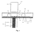
- This rewritable thin image display sheet (hereinafter referred to as "display sheet” for brevity) 10 fundamentally comprises a base layer 12, a transparent layer 14 disposed apart from the base layer 12 by a given distance for achieving a desirably reduced thickness, and a medium made of a low-temperature-melting material, specifically a low-melting-point wax 18, and filled in the space between the base layer 12 and the transparent layer 14.
- the low-melting-point wax 18 contains a magnetic powder 16 formed through an emulsion polymerization process and homogeneously dispersed therein. Further, the low-melting-point wax 18 is changeable between a first phase where the magnetic powder 16 is allowed to be displaced and a second phase where the magnetic powder is prohibited from being displaced.
- the base layer 12 is composed of a resistive layer 12A having a given electrical resistance, and an electrode layer 12B disposed to cover a surface of the resistive layer 12A.
- the resistive layer 12A is formed of a polyimide resin sheet containing carbon dispersed therein to have the given electrical resistance so as to generate heat in response to a current passed therethrough.
- the electrode layer 12B is composed of a nickel electrode coated on the entire inner surface of the resistive layer 12A.
- the resistive layer 12A is formed of a carbon-loaded polyimide cast film containing about 20 to 30% of carbon to adjust its electrical resistivity in the range of 10 to 300 O ⁇ cm.
- the resistive layer 12A may be formed of an accetylcellulose or polycarbonate film.
- the resistive layer contains carbon to secure conductivity.
- the carbon is contained in the form of nano-particles.
- the resistive layer may contain a carbon nano-tube or carbon fullerene. In case of using a carbon nano-tube, it can be contained in the resistive layer only at about 2 to 5 % to achieve the above electrical resistivity.
- the nickel electrode serving as the above electrode layer 12B may be deposited on the inner surface of the resistive layer 12A through an electroless plating process, a vacuum deposition process or a sputtering process.
- each of the spacers 20 is formed in a spherical bead shape. More specifically, the spacers 20 are formed of glass beads having a diameter of about 10 ⁇ m as a central value (a size distribution ranging from 5 to 15 ⁇ m). The diameter of the bead spacer 20 is set at a value at least 5 times greater than the particle size of the magnetic powder 16.
- the spacer is preferably made of a material having a specific gravity less different from that of the low-melting-point wax 19, such as synthetic resin or divinyl benzene with a specific gravity of 1.19.
- the spacers 20 may be provided at a mixing ratio of about 5 to 10%.
- the low-melting-point wax 18 is made of petroleum-based paraffin having a melting point ranging from 60 to 120°C, and colored in white using a white pigment.
- this white pigment has a high degree of whiteness and a high refractive index.
- the white pigment may be formed of TiO, SiO 2 , Al 2 O 3 , ArO 2 or CaCO 3 while powder having a particle size of about 0.3 ⁇ m, and mixed with the paraffin in the range of about 30 to 50 wt%.
- the magnetic powder 16 is formed to have a different color from that of the low-melting-point wax 18.
- the magnetic powder 16 is formed of ferrite powder colored in black.
- the magnetic powder 16 made of iron oxide has a particle size of about 5 to 10 ⁇ m. The structure of the magnetic powder 16 will be described in detail later.
- the transparent layer 14 is composed of a panel made of heat-resistant transparent synthetic resin, such as vinylidene chloride. More specifically, the transparent layer 14 is formed of a transparent film having a heat resistance against about 130°C. Preferably, the transparent layer 14 has a refractive index less different from that of the low-melting-point wax 18.
- the transparent layer 14 is preferably made of synthetic resin, such as meta-acrylic resin, polychlorotrifluoroethylene, vinylidene polyfluoride, acetylcellulose or polyester. The outer surface of the transparent layer 14 is coated with an anti-reflection film (not shown).
- Each of the base layer 12 and the transparent layer 14 is formed to have flexibility.
- the display sheet 10 can have a thin shape and flexibility in its entirety to satisfy the requirement as a paper-like structure so as to provide an image display sheet structure in place of conventional sheets (papers).
- An image display apparatus 30 (hereinafter referred to as "display apparatus" for brevity) incorporating the aforementioned display sheet 10 so as to display an arbitrary image in a rewritable state on the display sheet 10 will be described in detail below.
- This display apparatus 30 is designed such that the display sheet is detachably attached thereto, and an arbitrary image can be written in a rewritable state on the attached display sheet 10. Further, the display sheet 10 is designed such that it can be detached from the display apparatus 30 after the written image is fixed (stabilized), and freely carried while maintain the image in the fixed state.
- the display apparatus comprises a current supply head 32 serving as heating/melting means for heating a zone of the low-melting-point wax 18 of the display sheet 10 corresponding to an image display to melt the zone of the low-melting-point wax 18, a magnetic head 34 serving as displacement means which is disposed on the side of the transparent layer 14 of the display sheet 10 to be located adjacent to the outer surface of the transparent 14 in a non-contact manner and in opposed relation to the current supply head 32 while interposing the display sheet 10 therebetween, and adapted to displace the black magnetic powder 16 in the molten zone of the low-melting-point wax 18, toward the transparent layer 14, and a scan mechanism for moving the current supply head 32 and the magnetic head 34 integrally along the surface of the display sheet 20.
- the display apparatus 30 includes a ground terminal to be electrically connected to the electrode layer 12B constituting the base layer 12 when the display sheet 10 is attached to the display apparatus 30.
- the scan mechanism is operable, but not shown in detail, to move the current supply head 32 and the magnetic head 34 along an auxiliary scan direction corresponding to the rightward/leftward direction in FIG. 1 and along a primary scan direction corresponding to a direction orthogonal to the surface of the drawing sheet.
- the current supply head 32 and the magnetic head 34 can be scanningly moved along the entire surface of the display sheet 10. That is, in the zone of the low-melting-point wax 18 which has been molten by the current supply head 32, a given image can be displayed on the display sheet 10 in accordance with the black magnetic powder 16 which has been displaced onto the transparent layer 14 by the magnetic head 34.
- the current supply head 32 includes a current supply electrode 32A disposed in contactable relation to the resistive layer 12A of the base layer 12, and a ceramic electrode guard 32B surrounding the outer periphery of the current supply electrode 32A.
- the current supply electrode 32A is formed in a needle shape.
- the area of a portion of the current supply electrode 32A to be in contact with the resistive layer 12A is determined in connection with an intended resolution of an image to be displayed. In this embodiment, the contact area is set at 60 ⁇ 60 ⁇ m for a resolution of 400 dpi, and at 20 ⁇ 20 ⁇ m for a resolution of 1200 dpi.
- the current supply electrode 32A having an extremely small contact portion with the resistive layer 12A can concentratedly or locally pass a current between the contact portion and the electrode layer 12B, so that the current is passed through only the region of the resistive layer 12A corresponding to the position in contact with the current supply electrode 32A. Therefore, as shown in FIG. 2 , the current-passing region of the resistive layer 12A determined by the position in contact with the current supply electrode 32A will generate heat so as to selectively heat and melt a zone of the low-melting-point wax 18 adjacent to the heat-generation region.
- the display apparatus is designed such that the resistive layer 12A heated in conjunction with the above current supply operation in the current supply head 32 has a temperature of 150 to 200°C.
- the low-melting-point wax 18 has a melting point of 60 to 110°C.
- the magnetic head 34 is composed of a permanent magnet.
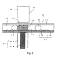
- the black magnetic powder 16 contained in the zone of the low-melting-point wax 18 heated and molted by the current from the current supply head 32 is drawn by a magnetic force of the magnetic head 34 composed of the permanent magnet, and displaced toward the transparent layer 14.
- the black magnetic powder 16 displaced onto the inner surface of the transparent layer 14 can be visually seen through the transparent layer 14 to serve as 1 (one) dot of an image to be displayed.
- the display sheet 10 is attached to the image display apparatus 30, and the electrode layer 12B is connected to the ground terminal (not shown) to go through the preparation for an image writing operation. Then, the current supply head 32 and the magnetic head 34 are moved to a writing initial position by a control unit (not shown). A given scanning operation is initiated from the writing initial position.
- the current supply head 32 and the magnetic head 34 start linear movement together, and a current is supplied through the current supply electrode 32A of the current supply head 32 only for a given time of period every time they are moved to a position corresponding to each of dots (pixels) as the basic unit of image to be displayed.
- the current is passed between the current supply electrode 32A and the electrode layer 12B.
- the resistive layer 12A the current is passed through only a region of the resistive layer 12A corresponding to the contact position with the current supply electrode 32A to allow only the current-passing region to generate heat.
- the current-passing region of the resistive layer 12A serves as a heat-generation region to melt a zone 18' of the low-melting-point wax 18 corresponding to the heat-generation region in accordance with the generated heat, as indicated by the shaded zone in FIG 2 , and the black magnetic powder 16 contained in the molten zone 18' of the low-melting-point wax 18 is displaced toward the transparent layer 14 by a magnetic force of the magnetic head 34 moved integrally with the current supply head 32.
- the displaced black magnetic powder 16 is collected on the inner surface of the transparent layer 14 as shown in FIG. 3 to form a black dot in one pixel.
- a black-dot-based coloring operation is completed in one zone corresponding to one given pixel. Subsequently, the current supply head 32 and the magnetic head 34 are moved to a position corresponding to an adjacent second pixel along the auxiliary scan direction. If the black-dot-based coloring operation is performed in the second pixel, the same process as described above will be repeated. Otherwise, when white color is left as ground color without performing the black-dot-based coloring operation, the entire current supply operation is omitted, and the current supply head 32 and the magnetic head 34 are moved to a position corresponding to an adjacent third pixel.
- the current supply head 32 and the magnetic head 34 are returned to the original or initial position, and then moved along the primary scan direction by a distance corresponding to one pixel. Then, the same display operation as described above is repeatedly performed along the auxiliary scan direction.
- a current is passed through the entire surface of the resistive layer 12A to heat and melt the entire zone of the low-melting-point wax 18. Then, during melting in the entire zone of the low-melting-point wax 18, the black magnetic powder 16 is moved toward the base layer 12 using a permanent magnet disposed on the side of the base layer 12 to remove the block magnetic powder completely from the transparent layer 14 and preclude any image from being displayed on the transparent layer 14. That is, any image on the display sheet is erased.
- the magnetic powder in above embodiment is formed as the black magnetic powder 16, the present invention is not limited to such a specific color, but the magnetic powder may be formed to have any other suitable color different from that of the low-melting-point wax 18 serving as a ground color.
- the base layer 12 may includes a resistive layer 12A having a given electrical resistance, and a pair of electrode layers 12B, 12C each disposed to cover a corresponding one of the opposite surfaces of the resistive layer 12A and formed with a matrix-shaped conductive pattern.
- the respective conductive patterns of the electrode layers may have plural pairs of opposed intersection points to be selectively supplied with a current therebetween, and a region corresponding to a pixel may be determined by the selected intersection points of the respective conductive patterns, according to a control signal arranged separately.
- a current is passed through the region of the resistive layer 12A located between the selected intersection points to selectively generate heat in the current-passing region of the resistive layer 12A.
- the matrix-shaped electrode layers 12B, 12C can be electrically scanned according to the control signal to display an image on the entire surface of the display sheet.
- a base layer 12 itself may be formed of a transparent sheet. In this case, it is necessary to prepare a heat-generation plate 40 corresponding to the base layer having the resistive layer 12A and the electrode layer 12B.
- an image can be displayed on any of the front and back surfaces of the display sheet 10' to provide usability close to that of papers and enhanced effectiveness.
- the display sheet 10' has no structure corresponding to the base layer 12 in the aforementioned embodiment, or does not include the resistive layer 12A and the electrode layer 12B.
- the display sheet 10' can have a simplified structure, and enhanced ductility or flexibility as compared to the display sheet 10 in the aforementioned embodiment to provide further improved usability.
- the means for displaying a given image on the display sheet 10' in the second modification is not limited to the heat-generation plate 40, but a conventional thermal head (not shown) may be used.
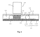
- an image display apparatus 30A may includes a cooling head 50 which is attached onto the side surface of a magnetic head 34 on the upstream side relative to the auxiliary scan direction, and adapted to cool a low-melting-point wax 18 in its molten state within a short period of time so as to fix (stabilize) an displayed image.
- the cooling head 50 is a water-cooled type designed such that the front end face of the cooling head 50 serving as a cooling surface is brought into contact with the outer surface of a transparent layer 14.
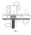
- a magnetic head 60 may comprise a core 60A made of a material having a high magnetic permeability and a coil 60B wound around the outer periphery of the core 60A.
- the magnetic head 60 may comprise a core composed of a permanent magnet, and a coil wound around the outer periphery of the permanent magnet.
- a magnetic force of the permanent magnet can be varied by exciting the coil or supplying current to the coil.
- a displacement force to a magnetic powder 16 can be varied by controlling the amount of current to be supplied to the coil 60B.
- plural kinds of magnetic powders 16 different in particle size are used.
- a small amount of current is first supplied to displace the magnetic powder 16 with a large particle size toward a transparent layer 14, and then the amount of current is gradually increased to displace magnetic powder 16 with a smaller particle size sequentially toward the transparent layer 14. In this manner, the amount of current can be controlled to display an image with excellent gradation expressing.
- the amount of current can be varied to display an image with different colors or with multicolor (colorization)
- the present invention is not limited to such a structure.
- FIG 8 as a fifth modification not covered by the claims, it may be designed to display an image on each of the surfaces.
- a rewritable thin image display sheet 70 in the fifth modification comprises a lower transparent layer 72 disposed at a position corresponding to the base layer 12 in the aforementioned embodiment, an upper transparent layer disposed at a position corresponding to the transparent layer 74, and an intermediate heat-generation layer 76 disposed between the upper and lower transparent layers and formed to have the same structure as that of the base layer 12 in the first modification not covered by the claims.
- the display sheet 70 further includes a low-melting-point wax 16A filled in the space between the intermediate heat-generation layer 76 and the lower transparent layer 72 while containing a magnetic powder 16A dispersed therein, and a low-melting-point wax 16B filled in the space between the intermediate heat-generation layer 76 and the upper transparent layer 74 while containing a magnetic powder 16B dispersed therein.
- a positions of each of matrix-shaped electrode layers 12B, 12C corresponding to a pixel to be used for displaying an image is defined by a given intersection of orthogonally crossing electrode wirings, and a current is passed through a region of a resistive layer 12A located between the respective interconnections of the electrode layers 12B, 12C, so as to generate heat in the region of the resistive layer 12A corresponding to the intersections.
- the low-melting-point wax 18A, 18B located, respectively, on the lower and upper sides of the heat-generation region of the resistive layer 12A are molten.
- An image display apparatus 78 for displaying an image on the above image display sheet comprises a control terminal (not shown) to be connected to the electrode layers 12B, 12C, a cooling head 80 disposed under the image display sheet 70, and a magnetic head 82 disposed above the image display sheet 70.
- the image display apparatus 78 constructed as above, when an image is displayed on the upper transparent layer 74 of the display sheet 70, a current is passed through a region of the intermediate heat-generation layer 76 corresponding to a given pixel, to generate heat in the region so as to melt the lower low-melting-point wax 18A together with the upper low-melting-point wax 18B.
- the magnetic powder 16B dispersed in a molten zone 18' of the upper low-melting-point wax 18B is displaced onto the upper transparent layer 74 by a magnetic head 82 to display an image on the upper transparent layer 74.
- the lower low-melting-point wax 18A is also molten in conjunction with the heat generation of the intermediate heat-generation layer 76.
- the magnetic powder 16A dispersed in the lower low-melting-point wax 18A has already been displaced onto the lower transparent layer 72 to display an image. Even in such a case, a portion of the molten zone 18A' adjacent to the lower transparent layer 72 is cooled by the cooling head 80. Thus, the heat from the intermediate heat-generation layer 76 is not transferred to the low-melting-point wax 18A around the magnetic powder 16A displaced in the vicinity of the lower transparent layer 72.
- the magnetic powder 16A displaced in the vicinity of the lower transparent layer 72 to form the image on the lower transparent layer 72 is held in the vicinity of the lower transparent layer 72 without being displaced toward the intermediate heat-generation layer 76 by the magnetic head 82. That is, there is no risk of disarrangement in an image displayed on the lower transparent layer 72, due to the magnetic head 82.
- an image can be displayed on either one of the front and back surfaces of the display sheet, or on both the front and back surfaces of the display sheet simultaneously, to provide usability closer to that of papers and enhanced effectiveness.
- the low-melting-point wax 18 in the aforementioned embodiment is made of petroleum-based paraffin
- the present invention is not limited to such a material.
- the low-melting-point wax 18 may be made of polyethylene terephthalate (PET) having a low melting point of 73°C. It is understood that a mixture of petroleum-based paraffin and PET may also be used.
- the heating means uses the technique of passing a current through the resistive layer to generate heat therein, as the heating means, the present invention is not limited to such a technique. It is understood that the heating means may be a technique using thermal head, or another technique of irradiating a sheet with a light absorption layer with laser light to generate heat precisely.
- the magnetic powder in the aforementioned embodiment is made of ferrite colored in black
- the present invention is not limited to such a material.
- the magnetic powder may be iron powder or ferrous oxide powder.
- ferrous oxide powder inherently exhibits block color.
- the magnetic powder may be composed of a magnetic fluid.
- spacer 20 in the aforementioned embodiment is formed in a bead shape
- the present invention is not limited to such a shape, but the spacer 20 may be formed in any other suitable shape, such as columnar or cylindrical shape.
- the medium 18 in which the magnetic powder 16 is dispersed may be a low-temperature-melting material which exhibits the first phase at a high temperature and the second phase at a low temperature.
- the first phase and the second phase are a liquid phase and a solid phase, respectively.
- This type of medium includes low-temperature-melting material, such as low-melting-point wax; colloid, such as glycerin fatty acid ester; and unstable or quasi-stable gel, such as agar, gelatin, aluminum hydroxide, ferric hydroxide or bentonite, which utilizes sol-gel phase change (or fluidization based on light, ultrasound, magnetic oscillation, heating, magnetic field or electrolysis).
- low-temperature-melting material such as low-melting-point wax
- colloid such as glycerin fatty acid ester
- unstable or quasi-stable gel such as agar, gelatin, aluminum hydroxide, ferric hydroxide or bentonite, which utilizes sol-gel phase change (or fluidization based on light, ultrasound, magnetic oscillation, heating, magnetic field or electrolysis).
- the low-melting-point wax 18 used as a low-temperature-melting material in the aforementioned embodiment is made of petroleum-based paraffin
- the present invention is not limited to such a material.
- the low-melting-point wax 18 may be made of natural wax or carnauba wax.
- cooling head 50 may be any other suitable cooling type, such as a forced-air-cooling type using an electric fan, a naturally-air-cooling type using fins, or a heat-pipe-based cooling system.
- image erasing means has not been described in the above modifications 1 to 5 for simplifying the explanation, it is preferable to provide an image erasing mechanism in the image display apparatus 30 of the present invention.
- an image display apparatus incorporating an image erasing mechanism 84 will be described.
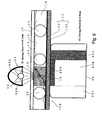
- FIG. 9 shows an image display apparatus 30B as a sixth modification. Except for the image erasing mechanism 84, and a writing/erasing head 86 as a substitute for the current supply head 32, the image display apparatus 30B has substantially the same structure as that of the aforementioned image display apparatus 30.
- the writing/erasing head 86 is formed to have a width in a moving direction greater than that of the current supply head 32. More specifically, the width of the writing/erasing head 86 is set at a value greater than a distance between adjacent spaces 20. Thus, even if the writing/erasing head 86 is strongly pressed onto a resistive layer 12A of a base layer 12 during a writing or erasing operation, at least one spacer 20 can be unexceptionally located within the pressed region to reliable maintain the distance or space between the base layer 12 and a transparent layer 14.
- the writing/erasing head 86 includes a line electrode serving as a writing head section 86A located on the downstream side relative to the moving direction thereof, which corresponds to the aforementioned current supply head 32, a line magnetic erasing head 86B located in the central portion thereof, and a cooling head 86C located on the upstream side, which has the same structure as that of the cooling head 80 in the aforementioned embodiment.
- a surface of the line magnetic erasing head 86B on the side of the display sheet 10 is covered with a low-friction heat-insulation member 86 D.
- the line magnetic erasing head 86B provided in the writing/erasing head 86 serves as a part of the image erasing mechanism 84.
- a selective erasing head 88 serving as the remaining part of the image erasing mechanism 84 is disposed on the opposite site of the writing/erasing head 86 relative to the display sheet 10.
- the selective erasing head 88 includes an infrared lamp 88A, and an elliptic mirror 88B covering the infrared lamp 88A to concentrate infrared heat generated from the infrared lamp 88A in a region of the display sheet 10 to be subjected to an image erasing operation.
- This selective erasing head 88 is associated with a transfer mechanism (not shown) to be moved in synchronous with the writing/erasing head 86.
- the selective erasing head 88 is designed, not shown in detail, such that it can be moved along a direction orthogonal to the display sheet 10 (or a direction getting close to/away from the display sheet 10), and the focal position of the elliptic mirror 88B can be adjusted to reliably heat a low-melting-point wax 18 depending on the thickness of the transparent layer 14 of the display sheet 10.
- the selective erasing head 88 movable along a direction orthogonal to the display sheet 10 allows energy/unit area given to the display sheet to be adjusted so as to set the correlation between the energy and a speed of the writing/erasing head 86 in the moving direction (or erasing speed) to assure the reliability of the erasing operation.
- a detector for detecting an image unformed region (or white region) of the display sheet 10 during the image erasing operation of the image erasing mechanism 84 may be provided.
- the erasing speed in a moving region corresponding to the detected white region can be increased to reduce the time required for the erasing operation.
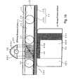
- the mage display apparatus 30C has substantially the same structure as that of the image display apparatus 30B in the sixth modification.
- the selective erasing head 88 of the image display apparatus 30C has a parabolic mirror 88C.
- the parabolic mirror 88C in the selective erasing head 88 changes the light emitted from an infrared lamp 88A into parallel light, and allows a display sheet 10 to be irradiated with the parallel light.
- the mage display apparatus 30C in the seventh modification can heat the display sheet in a wider range.
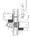
- the present invention is not limited to such a structure, but a laser system may be used as shown in FIG. 11 as an eighth modification not covered by the claims.
- the laser system 90 serving as image writing means in the eighth modification comprises a high-power semiconductor laser 90A serving as a power source, a collimator lens 90B for changing laser light from the semiconductor laser 90A into parallel light, a focusing lens 90C for focusing the laser light from the collimator lens 90B to a given spot diameter, and a polygon mirror 90D for performing a scanning operation with the laser light from the focusing lens 90.
- An arbitrary image can be written on the display sheet using the laser system 90.
- the laser light can be emitted from any directions.
- the laser light can be emitted only from the side of the transparent layer 14.
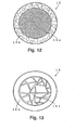
- the magnetic powder particle 16 includes a magnetic core 16a and a color coating layer 16b covering over the outer periphery of the magnetic core 16a.
- the magnetic core 16a is formed of a spherical sintered ferrite particle
- the color coating layer 16b is made of silicone resin having a thickness of about 1 to 3 ⁇ m. This silicone resin may be solid. If there is the need for the adjustment of specific gravity, the silicone resin may be prepared in the form of sponge through a forming process using a foaming agent.
- the magnetic core 16a may be formed of a fine ferrite powder solidified with a binder.
- the color coating layer 16b may be made of TFE (tetrafluoroethyleneor) or PTFE (polytetrafluoroethylene).
- FIG 13 shows another example of a magnetic powder different from the magnetic powder 16 in FIG 12 .
- a magnetic core 16a of the magnetic powder particle 16 is formed of a spherical agglomerate of granular sintered ferrite, or a spherical agglomerate of crystalline ferrite.
- the present invention provides a rewritable thin image display sheet, an image display apparatus and an image display system, capable of reliably displaying an image in a rewritable state while achieving a significantly simplified structure.
- the present invention also provides a rewritable thin image display sheet, an image display apparatus and an image display system, capable of reliably displaying an image with an enhanced resolution while achieving a significantly simplified structure.
- the present invention provides a rewritable thin image display sheet, an image display apparatus and an image display system, capable of reliably displaying an image while achieving a significantly simplified structure having a significantly reduced thickness.
- the present invention provides a rewritable thin image display sheet, an image display apparatus and an image display system, capable of reliably displaying an image with an excellent gradation expression while achieving a significantly simplified structure.
Landscapes
- Physics & Mathematics (AREA)
- Optics & Photonics (AREA)
- Nonlinear Science (AREA)
- Engineering & Computer Science (AREA)
- Power Engineering (AREA)
- General Physics & Mathematics (AREA)
- Chemical & Material Sciences (AREA)
- Inorganic Chemistry (AREA)
- Electrochromic Elements, Electrophoresis, Or Variable Reflection Or Absorption Elements (AREA)
- Devices For Indicating Variable Information By Combining Individual Elements (AREA)
- Overhead Projectors And Projection Screens (AREA)
- Laminated Bodies (AREA)
Claims (34)
- Feuille d'affichage d'image mince réinscriptible (10 ; 70) comprenant :une couche de base (12 ; 76) ;une couche transparente (14 ; 72, 74) disposée écartée d'une certaine distance de ladite couche de base (12 ; 76) ; etun milieu (18 ; 18A, 18B) rempli dans l'espace entre ladite couche de base (12 ; 76) et ladite couche transparente (14 ; 72, 74), ledit milieu contenant une poudre magnétique (16) dispersée à l'intérieur, ledit milieu (18 ; 18A, 18B) étant adapté pour être changeable entre une première phase où ladite poudre magnétique (16 ; 16A, 16B) est autorisée à être déplacée et une deuxième phase où ladite poudre magnétique (16 ; 16A, 16B) est empêchée d'être déplacée, caractérisée en ce que :ladite couche de base (12 ; 76) comprend une couche résistante (12A) ayant une résistance électrique donnée et une couche d'électrode (12B, 12C) disposée pour couvrir une surface de ladite couche résistante (12A) sur le côté de ladite couche transparente (14 ; 72, 74), et en ce queladite couche d'électrode (12B, 12C) est une électrode globale recouvrant toute la surface de ladite couche résistante (12A) sur le côté de ladite couche transparente (14 ; 72, 74).
- Feuille d'affichage d'image mince réinscriptible (10 ; 70) selon la revendication 1, dans laquelle ledit milieu (18 ; 18A, 18B) est composé d'un matériau à fusion à basse température qui présente ladite première phase à une haute température et ladite deuxième phase à une basse température.
- Feuille d'affichage d'image mince réinscriptible (10 ; 70) selon l'une des revendications précédentes, dans laquelle ladite couche résistante (12A) comprend une feuille de résine synthétique contenant du carbone dispersé à l'intérieur pour avoir ladite résistance électrique donnée de manière à générer de la chaleur en réponse à un courant passé à travers celle-ci.
- Feuille d'affichage d'image mince réinscriptible (10 ; 70) selon la revendication 3, dans laquelle ledit carbone est sous la forme de particules de carbone, ayant de préférence une dimension de nanoparticule.
- Feuille d'affichage d'image mince réinscriptible (10 ; 70) selon l'une des revendications précédentes, dans laquelle ladite couche d'électrode (12B, 12C) comprend une électrode métallique qui est composée de préférence de nickel.
- Feuille d'affichage d'image mince réinscriptible (10 ; 70) selon l'une des revendications précédentes, qui comprend une entretoise (20) définissant la distance entre ladite couche de base (12 ; 76) et ladite couche transparente (14 ; 72, 74), où ladite entretoise (20) est formée de préférence sous une forme de perle.
- Feuille d'affichage d'image mince réinscriptible (10 ; 70) selon la revendication 6, dans laquelle ladite entretoise (20) a un diamètre au moins 5 fois plus grand que la dimension particulaire de ladite poudre magnétique (16 ; 16A, 16B).
- Feuille d'affichage d'image mince réinscriptible (10 ; 70) selon l'une des revendications précédentes, dans laquelle ladite couche de base (12 ; 76) est composée d'une couche transparente, et/ou dans laquelle ladite poudre magnétique (16) est colorée d'une couleur arbitraire.
- Feuille d'affichage d'image mince réinscriptible (10 ; 70) selon l'une des revendications précédentes et la revendication 2, dans laquelle ledit matériau à fusion à basse température (18 ; 18A, 18B) comprend une cire à bas point de fusion pour être fondue dans une plage de température de 60 à 120 °C, et/ou dans laquelle ledit matériau à fusion à basse température est coloré en blanc et ladite poudre magnétique (16) est colorée d'une couleur autre que le blanc, de préférence ladite poudre magnétique (16) est colorée en noir.
- Feuille d'affichage d'image mince réinscriptible (10 ; 70) selon l'une des revendications précédentes, dans laquelle ladite couche transparente (14 ; 72, 74) comprend un film réalisé en résine transparente et/ou est formée pour avoir une flexibilité.
- Feuille d'affichage d'image mince réinscriptible (10 ; 70) selon l'une des revendications précédentes, dans laquelle chacune de ladite couche de base (12 ; 76) et ladite couche transparente (14 ; 72, 74) est formée pour avoir une flexibilité.
- Feuille d'affichage d'image mince réinscriptible (10 ; 70) selon l'une des revendications précédentes, dans laquelle chacune des particules de ladite poudre magnétique (16) comprend un noyau magnétique (16a) et une couche de revêtement en résine (16b) recouvrant la périphérie extérieure dudit noyau magnétique (16a).
- Feuille d'affichage d'image mince réinscriptible (10 ; 70) selon la revendication 12, dans laquelle ledit noyau magnétique (16a) est formé d'une particule de ferrite frittée sphérique, ou d'une poudre de ferrite fine solidifiée avec un liant, ou d'un agglomérat sphérique de ferrite frittée granulaire, ou d'un agglomérat sphérique de ferrite cristalline.
- Feuille d'affichage d'image mince réinscriptible (10 ; 70) selon la revendication 12 ou 13, dans laquelle ladite couche de revêtement en résine (16b) est colorée d'une couleur arbitraire, et/ou dans laquelle la couche de revêtement en résine est formée comme un solide, et/ou dans laquelle la couche de revêtement en résine (16b) est formée à travers un processus de moussage.
- Dispositif d'affichage d'image (30 ; 30B ; 30C) pour afficher une image dans un état réinscriptible sur une feuille d'affichage d'image, ledit dispositif d'affichage d'image comprenant :la feuille d'affichage d'image mince réinscriptible (10 ; 70) selon la revendication 1 ;des moyens de changement de phase pour permettre à une zone dudit milieu correspondant à un pixel d'être changée sélectivement de ladite deuxième phase dans ladite première phase ; etdes moyens de déplacement (34) pour permettre à la poudre magnétique (16) dispersée dans ladite zone de milieu changée dans ladite première phase d'être déplacée vers ladite couche transparente (14 ; 72, 74), moyennant quoi une image donnée est affichée sur ladite feuille d'affichage d'image en fonction de ladite poudre magnétique (16) sur ladite couche transparente (14 ; 72, 74).
- Dispositif d'affichage d'image (30 ; 30B ; 30C) selon la revendication 15, dans lequel :ledit milieu est composé d'un matériau à fusion à basse température qui présente une phase liquide comme ladite première phase à une haute température et une phase solide comme ladite deuxième phase à une basse température ; etlesdits moyens de changement de phase sont des moyens de chauffage/fusion (32) pour chauffer ledit milieu jusqu'à ladite haute température.
- Dispositif d'affichage d'image (30 ; 30B ; 30C) selon la revendication 16, dans lequel lesdits moyens de chauffage/fusion (32) comprennent des moyens d'alimentation de courant pour faire passer un courant à travers une région sélectionnée arbitrairement de ladite couche résistante (12A) pour générer de la chaleur dans ladite région de passage de courant de ladite couche résistante (12A).
- Dispositif d'affichage d'image (30 ; 30B ; 30C) selon la revendication 17, dans lequel lesdits moyens d'alimentation de courant comprennent une tête d'alimentation de courant (32), où lesdits moyens d'alimentation de courant sont adaptés pour faire passer un courant entre une région de ladite couche résistante (12A) en contact avec ladite tête d'alimentation de courant (32) et ladite couche d'électrode (12B) de manière à générer sélectivement de la chaleur dans ladite région de passage de courant de ladite couche résistante (12A).
- Dispositif d'affichage d'image (30 ; 30B ; 30C) selon l'une des revendications 16 à 18, dans lequel les moyens de déplacement (34) sont adaptés pour déplacer ladite poudre magnétique (16) en fonction d'une force magnétique, et dans lequel lesdits moyens de déplacement comprennent de préférence un aimant permanent disposé sur le côté de ladite couche transparente (14 ; 72, 74) ou une tête magnétique ayant un électroaimant disposé sur le côté de ladite couche transparente (14 ; 72, 74).
- Dispositif d'affichage d'image (30 ; 30B ; 30C) selon la revendication 19, dans lequel lesdits moyens de déplacement comprennent une tête magnétique ayant un électroaimant disposé sur le côté de ladite couche transparente et dans lequel ledit électroaimant est adapté pour faire varier ladite force magnétique en fonction de la valeur de courant à délivrer à celui-ci.
- Dispositif d'affichage d'image (30 ; 30B ; 30C) selon l'une des revendications 16 à 20, dans lequel :lesdits moyens de chauffage/fusion sont disposés sur le côté de la couche de base (12 ; 76) ; etlesdits moyens de déplacement sont disposés sur le côté de ladite couche transparente (14 ; 72, 74) en relation opposée auxdits moyens de chauffage/fusion tout en interposant ledit matériau à fusion à basse température entre lesdits moyens de chauffage/fusion et lesdits moyens de déplacement,dans lequel lesdits moyens de déplacement sont de préférence disposés espacés de ladite couche transparente (14 ; 72, 74).
- Dispositif d'affichage d'image (30 ; 30B ; 30C) selon l'une des revendications 16 à 21, dans lequel ladite couche de base (12 ; 76) est composée d'une couche transparente.
- Dispositif d'affichage d'image selon l'une des revendications 16 à 22, qui comprend en outre des moyens de refroidissement (50) pour refroidir et solidifier ledit matériau à fusion à basse température dans une phase liquide.
- Dispositif d'affichage d'image selon la revendication 23, dans lequel lesdits moyens de refroidissement (50) sont disposés adjacents auxdits moyens de déplacement, et/ou dans lequel lesdits moyens de refroidissement (50) sont disposés en relation de mise en contact avec ladite couche transparente (14 ; 72, 74).
- Dispositif d'affichage d'image selon l'une des revendications 16 à 24, qui comprend en outre des moyens d'effacement d'image pour effacer une image visualisée sur ladite feuille d'affichage d'image.
- Dispositif d'affichage d'image selon la revendication 25, dans lequel lesdits moyens d'effacement d'image comprennent une tête d'effacement magnétique disposée sur le côté de ladite couche de base (12 ; 76) et une tête d'effacement sélectif disposée sur le côté de ladite couche transparente (14 ; 72, 74), dans lequel ladite tête d'effacement sélectif est de préférence adaptée pour être déplacée en synchronisme avec ladite tête d'effacement magnétique, et/ou dans lequel ladite tête d'effacement sélectif comprend de préférence une lampe à infrarouge et un miroir réfléchissant pour réfléchir la lumière et la chaleur émises à partir de ladite lampe à infrarouge vers ladite feuille d'affichage d'image.
- Dispositif d'affichage d'image selon la revendication 26, ladite tête d'effacement sélectif comprend une lampe à infrarouge et un miroir réfléchissant pour réfléchir la lumière et la chaleur émises à partir de ladite lampe à infrarouge vers ladite feuille d'affichage d'image et dans lequel ledit miroir réfléchissant est un miroir parabolique ou un miroir elliptique.
- Dispositif d'affichage d'image selon la revendication 26 ou 27, dans lequel ledit miroir d'effacement sélectif est adapté pour être mobile suivant une direction orthogonale à ladite feuille d'affichage d'image.
- Dispositif d'affichage d'image selon l'une des revendications 16 à 28, dans lequel lesdits moyens de chauffage/fusion comprennent un système laser.
- Procédé d'affichage d'image consistant à :prédisposer une feuille d'affichage d'image mince réinscriptible (10 ; 70) selon l'une quelconque des revendications 1 à 14, dans lequel ledit milieu (18 ; 18A, 18B) est composé d'un matériau à fusion à basse température ;permettre à une zone dudit matériau à fusion à basse température correspondant à un affichage d'image d'être sélectivement chauffé et fondu par ladite couche résistante capable de générer de la chaleur en réponse à un courant passé à travers celle-ci ; etdéplacer la poudre magnétique (16) dans ladite zone fondue vers ladite couche transparente (14 ; 72, 74) de manière à visualiser une image donnée sur ladite couche transparente (14 ; 72, 74).
- Procédé selon la revendication 30, dans lequel ladite poudre magnétique (16 ; 16A, 16B) dans ladite zone fondue est déplacée vers ladite couche transparente (14 ; 72, 74) au moyen d'une force magnétique.
- Procédé selon la revendication 30 ou 31, dans lequel ledit matériau à fusion à basse température (18 ; 18A, 18B) correspondant à un pixel dans ledit affichage d'image est chauffé et fondu par ladite couche résistante (12A).
- Procédé selon la revendication 30, 31 ou 32, comprenant, après que l'image est visualisée en fonction de ladite poudre magnétique déplacée (16 ; 16A, 16B), le refroidissement et la solidification de ladite zone fondue pour fixer ladite image.
- Procédé selon la revendication 33, qui comprend le chauffage et la fusion d'une partie dudit matériau à fusion à basse température solidifié (18 ; 18A, 18B) et ensuite le déplacement de ladite poudre magnétique (16 ; 16A, 16B) sur ladite couche transparente (14 ; 72, 74) vers ladite couche de base (12) pour effacer une partie de ladite image, ou qui comprend le chauffage et la fusion dudit matériau à fusion à basse température solidifié (18 ; 18A, 18B) dans sa totalité et ensuite le déplacement de ladite poudre magnétique (16) sur ladite couche transparente (14 ; 72, 74) vers ladite couche de base (12) pour effacer ladite image dans sa totalité.
Applications Claiming Priority (5)
| Application Number | Priority Date | Filing Date | Title |
|---|---|---|---|
| JP2002061170 | 2002-01-31 | ||
| JP2002061170 | 2002-01-31 | ||
| JP2003060635 | 2003-01-31 | ||
| JP2003060635A JP4033791B2 (ja) | 2002-01-31 | 2003-01-31 | リライタブル薄型画像表示シート、画像表示装置、及び、画像表示システム |
| PCT/JP2003/001026 WO2003065116A1 (fr) | 2002-01-31 | 2003-01-31 | Feuille d'affichage d'image mince reinscriptible, affichage d'image et systeme d' affichage d'image |
Publications (3)
| Publication Number | Publication Date |
|---|---|
| EP1480073A1 EP1480073A1 (fr) | 2004-11-24 |
| EP1480073A4 EP1480073A4 (fr) | 2007-03-28 |
| EP1480073B1 true EP1480073B1 (fr) | 2008-05-07 |
Family
ID=27667565
Family Applications (1)
| Application Number | Title | Priority Date | Filing Date |
|---|---|---|---|
| EP03703133A Expired - Lifetime EP1480073B1 (fr) | 2002-01-31 | 2003-01-31 | Feuille d'affichage d'image mince reinscriptible, affichage d'image et procede d'affichage d'image |
Country Status (8)
| Country | Link |
|---|---|
| US (2) | US7459218B2 (fr) |
| EP (1) | EP1480073B1 (fr) |
| JP (1) | JP4033791B2 (fr) |
| KR (1) | KR20040081160A (fr) |
| CN (1) | CN100343751C (fr) |
| AT (1) | ATE394703T1 (fr) |
| DE (1) | DE60320764D1 (fr) |
| WO (1) | WO2003065116A1 (fr) |
Families Citing this family (7)
| Publication number | Priority date | Publication date | Assignee | Title |
|---|---|---|---|---|
| JP2005070714A (ja) * | 2003-08-25 | 2005-03-17 | Majima Kenkyusho:Kk | リライタブル薄型画像表示シート |
| US7029773B2 (en) * | 2003-10-10 | 2006-04-18 | Seagate Technology Llc | Method and system for magnetic recording using self-organized magnetic nanoparticles |
| JP2005313533A (ja) * | 2004-04-30 | 2005-11-10 | Shinko Electric Co Ltd | リライタブルペーパー用磁気ヘッドおよびリライタブルプリンタ |
| JP2006257414A (ja) * | 2005-02-17 | 2006-09-28 | Kobe Univ | 磁気感熱式電子ペーパー用の磁性微粒子 |
| JP4742660B2 (ja) * | 2005-04-25 | 2011-08-10 | 富士ゼロックス株式会社 | 文書処理システム |
| JP4682761B2 (ja) * | 2005-09-12 | 2011-05-11 | ブラザー工業株式会社 | 電気泳動表示媒体および電気泳動表示媒体の製造方法 |
| TWI582924B (zh) * | 2016-02-02 | 2017-05-11 | 宏碁股份有限公司 | 散熱模組與電子裝置 |
Family Cites Families (23)
| Publication number | Priority date | Publication date | Assignee | Title |
|---|---|---|---|---|
| JPS4710236Y1 (fr) * | 1968-07-09 | 1972-04-17 | ||
| JPS517631Y2 (fr) | 1971-03-04 | 1976-03-01 | ||
| US4124735A (en) * | 1976-12-02 | 1978-11-07 | Xerox Corporation | Magnetic glass carrier materials |
| JPS5947676B2 (ja) * | 1977-04-11 | 1984-11-20 | 株式会社パイロット | 磁気パネル |
| US4603073A (en) * | 1983-12-22 | 1986-07-29 | Minnesota Mining And Manufacturing Company | Opaque polyester film containing fine carbon black particles |
| US4549824A (en) * | 1983-12-30 | 1985-10-29 | International Business Machines Corporation | Ink additives for efficient thermal ink transfer printing processes |
| JPH0224633A (ja) | 1988-07-13 | 1990-01-26 | Kinseki Ltd | 電気泳動表示装置 |
| JPH087532B2 (ja) * | 1989-01-23 | 1996-01-29 | 株式会社パイロット | 磁気泳動表示パネル |
| JPH03234751A (ja) * | 1990-02-08 | 1991-10-18 | Tokai Carbon Co Ltd | 高抵抗性面状発熱体の製造方法 |
| US5699097A (en) * | 1994-04-22 | 1997-12-16 | Kabushiki Kaisha Toshiba | Display medium and method for display therewith |
| JP2563765B2 (ja) * | 1994-12-05 | 1996-12-18 | 沖電気工業株式会社 | 表示装置 |
| JP3277796B2 (ja) * | 1996-03-08 | 2002-04-22 | 凸版印刷株式会社 | 磁気記録体 |
| JPH09281907A (ja) * | 1996-04-15 | 1997-10-31 | Sharp Corp | 磁気泳動表示装置 |
| JP3307243B2 (ja) * | 1996-10-11 | 2002-07-24 | 富士ゼロックス株式会社 | 可逆表示媒体及び画像表示方法 |
| JP3724085B2 (ja) * | 1996-11-21 | 2005-12-07 | 富士ゼロックス株式会社 | 画像表示用インク組成物、画像表示媒体及び画像表示方法 |
| JPH10260648A (ja) * | 1997-03-18 | 1998-09-29 | Fuji Xerox Co Ltd | 可逆性画像表示媒体の印字消去装置 |
| JP3587435B2 (ja) * | 1998-10-16 | 2004-11-10 | 株式会社タカラ | 表示パネル |
| AU3076300A (en) * | 1999-01-21 | 2000-08-07 | Miwa Science Laboratory Inc. | Image recording medium, image recording/erasing device, and image recording method |
| JP3559741B2 (ja) * | 1999-12-03 | 2004-09-02 | マークテック株式会社 | 磁気泳動表示用着色磁性粒子 |
| US6556262B1 (en) * | 2000-01-06 | 2003-04-29 | Eastman Kodak Company | Display sheet having memory using limited coalescence domains |
| JP2002162652A (ja) * | 2000-01-31 | 2002-06-07 | Fujitsu Ltd | シート状表示装置、樹脂球状体、及びマイクロカプセル |
| JP4114374B2 (ja) * | 2001-03-19 | 2008-07-09 | セイコーエプソン株式会社 | 電気泳動表示装置、電気泳動表示装置の駆動方法及び電子機器 |
| US6870661B2 (en) * | 2001-05-15 | 2005-03-22 | E Ink Corporation | Electrophoretic displays containing magnetic particles |
-
2003
- 2003-01-31 JP JP2003060635A patent/JP4033791B2/ja not_active Expired - Fee Related
- 2003-01-31 EP EP03703133A patent/EP1480073B1/fr not_active Expired - Lifetime
- 2003-01-31 KR KR10-2004-7011801A patent/KR20040081160A/ko not_active Ceased
- 2003-01-31 CN CNB038031876A patent/CN100343751C/zh not_active Expired - Fee Related
- 2003-01-31 DE DE60320764T patent/DE60320764D1/de not_active Expired - Lifetime
- 2003-01-31 WO PCT/JP2003/001026 patent/WO2003065116A1/fr not_active Ceased
- 2003-01-31 AT AT03703133T patent/ATE394703T1/de not_active IP Right Cessation
- 2003-01-31 US US10/502,942 patent/US7459218B2/en not_active Expired - Fee Related
-
2008
- 2008-11-03 US US12/289,721 patent/US20090073542A1/en not_active Abandoned
Also Published As
| Publication number | Publication date |
|---|---|
| CN100343751C (zh) | 2007-10-17 |
| US20050079300A1 (en) | 2005-04-14 |
| DE60320764D1 (de) | 2008-06-19 |
| US20090073542A1 (en) | 2009-03-19 |
| EP1480073A1 (fr) | 2004-11-24 |
| EP1480073A4 (fr) | 2007-03-28 |
| HK1079576A1 (en) | 2006-04-07 |
| CN1628265A (zh) | 2005-06-15 |
| ATE394703T1 (de) | 2008-05-15 |
| US7459218B2 (en) | 2008-12-02 |
| JP4033791B2 (ja) | 2008-01-16 |
| JP2003302660A (ja) | 2003-10-24 |
| WO2003065116A1 (fr) | 2003-08-07 |
| KR20040081160A (ko) | 2004-09-20 |
Similar Documents
| Publication | Publication Date | Title |
|---|---|---|
| US20090073542A1 (en) | Rewritable thin image display sheet, image display apparatus and image display system | |
| US5231450A (en) | Three-dimensional color image printer | |
| US5157011A (en) | Thermoreversible recording medium, apparatus utilizing the same and method for fabricating the same | |
| WO2000043835A1 (fr) | Support d'images, dispositif d'enregistrement/effacement d'images et procede d'enregistrement d'images | |
| JPH10260648A (ja) | 可逆性画像表示媒体の印字消去装置 | |
| JP4657270B2 (ja) | リライタブル薄型画像表示シート、画像表示装置、及び、画像表示システム | |
| US3673597A (en) | Method and apparatus for recording and/or displaying images utilizing thermomagnetically sensitive microscopic capsules | |
| JPH1039801A (ja) | 可逆性記録媒体の記録消去装置および記録消去方法 | |
| JP4122831B2 (ja) | 書き換え可能な表示媒体、表示装置およびこれらを用いた表示方法 | |
| JP3856271B2 (ja) | 継続表示可能な可撓性ディスプレー | |
| JP4925003B2 (ja) | 手書き込みが可能な表示媒体、表示装置および表示方法 | |
| JPH09160511A (ja) | 磁気記録体及びその記録方法 | |
| JP3633298B2 (ja) | 磁気表示媒体の表示情報の消去装置及び消去方法 | |
| JP2005070714A (ja) | リライタブル薄型画像表示シート | |
| JP2005283744A (ja) | 表示媒体およびフルカラー表示方法 | |
| WO1993007004A1 (fr) | Materiau thermoreversible de support d'enregistrement, son procede de production, et support d'enregistrement thermosensible | |
| JP2612287B2 (ja) | 情報記録表示体 | |
| SU941920A1 (ru) | Устройство дл записи изображений | |
| JPH09244556A (ja) | 磁気記録体 | |
| JPH1039798A (ja) | 可逆性磁気記録媒体の印字消去ヘッド | |
| JP3289566B2 (ja) | 磁気表示媒体の記録装置 | |
| JPH1044592A (ja) | 可逆的記録媒体 | |
| JPH01285381A (ja) | 画像形成装置 | |
| JP2003322882A (ja) | 書き換え可能な表示媒体、表示装置およびこれらを用いた表示方法 | |
| JPH07104684A (ja) | 磁気表示用ディスプレー及び磁気表示装置 |
Legal Events
| Date | Code | Title | Description |
|---|---|---|---|
| PUAI | Public reference made under article 153(3) epc to a published international application that has entered the european phase |
Free format text: ORIGINAL CODE: 0009012 |
|
| 17P | Request for examination filed |
Effective date: 20040830 |
|
| AK | Designated contracting states |
Kind code of ref document: A1 Designated state(s): AT BE BG CH CY CZ DE DK EE ES FI FR GB GR HU IE IT LI LU MC NL PT SE SI SK TR |
|
| AX | Request for extension of the european patent |
Extension state: AL LT LV MK RO |
|
| RIC1 | Information provided on ipc code assigned before grant |
Ipc: B41M 5/36 20060101ALI20061020BHEP Ipc: G02F 1/09 20060101AFI20061020BHEP Ipc: G09F 9/37 20060101ALI20061020BHEP |
|
| A4 | Supplementary search report drawn up and despatched |
Effective date: 20070226 |
|
| 17Q | First examination report despatched |
Effective date: 20070514 |
|
| RTI1 | Title (correction) |
Free format text: REWRITABLE THIN IMAGE DISPLAY SHEET, IMAGE DISPLAY, AND METHOD FOR IMAGE DISPLAYING |
|
| GRAP | Despatch of communication of intention to grant a patent |
Free format text: ORIGINAL CODE: EPIDOSNIGR1 |
|
| GRAS | Grant fee paid |
Free format text: ORIGINAL CODE: EPIDOSNIGR3 |
|
| GRAA | (expected) grant |
Free format text: ORIGINAL CODE: 0009210 |
|
| AK | Designated contracting states |
Kind code of ref document: B1 Designated state(s): AT BE BG CH CY CZ DE DK EE ES FI FR GB GR HU IE IT LI LU MC NL PT SE SI SK TR |
|
| REG | Reference to a national code |
Ref country code: GB Ref legal event code: FG4D |
|
| REG | Reference to a national code |
Ref country code: CH Ref legal event code: EP |
|
| REG | Reference to a national code |
Ref country code: IE Ref legal event code: FG4D Free format text: LANGUAGE OF EP DOCUMENT: FRENCH |
|
| REF | Corresponds to: |
Ref document number: 60320764 Country of ref document: DE Date of ref document: 20080619 Kind code of ref document: P |
|
| PG25 | Lapsed in a contracting state [announced via postgrant information from national office to epo] |
Ref country code: SI Free format text: LAPSE BECAUSE OF FAILURE TO SUBMIT A TRANSLATION OF THE DESCRIPTION OR TO PAY THE FEE WITHIN THE PRESCRIBED TIME-LIMIT Effective date: 20080507 |
|
| PG25 | Lapsed in a contracting state [announced via postgrant information from national office to epo] |
Ref country code: NL Free format text: LAPSE BECAUSE OF FAILURE TO SUBMIT A TRANSLATION OF THE DESCRIPTION OR TO PAY THE FEE WITHIN THE PRESCRIBED TIME-LIMIT Effective date: 20080507 Ref country code: ES Free format text: LAPSE BECAUSE OF FAILURE TO SUBMIT A TRANSLATION OF THE DESCRIPTION OR TO PAY THE FEE WITHIN THE PRESCRIBED TIME-LIMIT Effective date: 20080818 Ref country code: FI Free format text: LAPSE BECAUSE OF FAILURE TO SUBMIT A TRANSLATION OF THE DESCRIPTION OR TO PAY THE FEE WITHIN THE PRESCRIBED TIME-LIMIT Effective date: 20080507 |
|
| NLV1 | Nl: lapsed or annulled due to failure to fulfill the requirements of art. 29p and 29m of the patents act | ||
| PG25 | Lapsed in a contracting state [announced via postgrant information from national office to epo] |
Ref country code: AT Free format text: LAPSE BECAUSE OF FAILURE TO SUBMIT A TRANSLATION OF THE DESCRIPTION OR TO PAY THE FEE WITHIN THE PRESCRIBED TIME-LIMIT Effective date: 20080507 |
|
| PG25 | Lapsed in a contracting state [announced via postgrant information from national office to epo] |
Ref country code: DK Free format text: LAPSE BECAUSE OF FAILURE TO SUBMIT A TRANSLATION OF THE DESCRIPTION OR TO PAY THE FEE WITHIN THE PRESCRIBED TIME-LIMIT Effective date: 20080507 Ref country code: PT Free format text: LAPSE BECAUSE OF FAILURE TO SUBMIT A TRANSLATION OF THE DESCRIPTION OR TO PAY THE FEE WITHIN THE PRESCRIBED TIME-LIMIT Effective date: 20081007 Ref country code: SE Free format text: LAPSE BECAUSE OF FAILURE TO SUBMIT A TRANSLATION OF THE DESCRIPTION OR TO PAY THE FEE WITHIN THE PRESCRIBED TIME-LIMIT Effective date: 20080807 Ref country code: CZ Free format text: LAPSE BECAUSE OF FAILURE TO SUBMIT A TRANSLATION OF THE DESCRIPTION OR TO PAY THE FEE WITHIN THE PRESCRIBED TIME-LIMIT Effective date: 20080507 |
|
| PG25 | Lapsed in a contracting state [announced via postgrant information from national office to epo] |
Ref country code: SK Free format text: LAPSE BECAUSE OF FAILURE TO SUBMIT A TRANSLATION OF THE DESCRIPTION OR TO PAY THE FEE WITHIN THE PRESCRIBED TIME-LIMIT Effective date: 20080507 Ref country code: BE Free format text: LAPSE BECAUSE OF FAILURE TO SUBMIT A TRANSLATION OF THE DESCRIPTION OR TO PAY THE FEE WITHIN THE PRESCRIBED TIME-LIMIT Effective date: 20080507 |
|
| PLBE | No opposition filed within time limit |
Free format text: ORIGINAL CODE: 0009261 |
|
| STAA | Information on the status of an ep patent application or granted ep patent |
Free format text: STATUS: NO OPPOSITION FILED WITHIN TIME LIMIT |
|
| 26N | No opposition filed |
Effective date: 20090210 |
|
| PG25 | Lapsed in a contracting state [announced via postgrant information from national office to epo] |
Ref country code: BG Free format text: LAPSE BECAUSE OF FAILURE TO SUBMIT A TRANSLATION OF THE DESCRIPTION OR TO PAY THE FEE WITHIN THE PRESCRIBED TIME-LIMIT Effective date: 20080807 Ref country code: EE Free format text: LAPSE BECAUSE OF FAILURE TO SUBMIT A TRANSLATION OF THE DESCRIPTION OR TO PAY THE FEE WITHIN THE PRESCRIBED TIME-LIMIT Effective date: 20080507 |
|
| PG25 | Lapsed in a contracting state [announced via postgrant information from national office to epo] |
Ref country code: IT Free format text: LAPSE BECAUSE OF FAILURE TO SUBMIT A TRANSLATION OF THE DESCRIPTION OR TO PAY THE FEE WITHIN THE PRESCRIBED TIME-LIMIT Effective date: 20080507 Ref country code: MC Free format text: LAPSE BECAUSE OF NON-PAYMENT OF DUE FEES Effective date: 20090131 |
|
| REG | Reference to a national code |
Ref country code: CH Ref legal event code: PL |
|
| GBPC | Gb: european patent ceased through non-payment of renewal fee |
Effective date: 20090131 |
|
| REG | Reference to a national code |
Ref country code: IE Ref legal event code: MM4A |
|
| PG25 | Lapsed in a contracting state [announced via postgrant information from national office to epo] |
Ref country code: LI Free format text: LAPSE BECAUSE OF NON-PAYMENT OF DUE FEES Effective date: 20090131 Ref country code: CH Free format text: LAPSE BECAUSE OF NON-PAYMENT OF DUE FEES Effective date: 20090131 |
|
| REG | Reference to a national code |
Ref country code: FR Ref legal event code: ST Effective date: 20091030 |
|
| PG25 | Lapsed in a contracting state [announced via postgrant information from national office to epo] |
Ref country code: GB Free format text: LAPSE BECAUSE OF NON-PAYMENT OF DUE FEES Effective date: 20090131 |
|
| PG25 | Lapsed in a contracting state [announced via postgrant information from national office to epo] |
Ref country code: IE Free format text: LAPSE BECAUSE OF NON-PAYMENT OF DUE FEES Effective date: 20090131 |
|
| PG25 | Lapsed in a contracting state [announced via postgrant information from national office to epo] |
Ref country code: FR Free format text: LAPSE BECAUSE OF NON-PAYMENT OF DUE FEES Effective date: 20090202 |
|
| PG25 | Lapsed in a contracting state [announced via postgrant information from national office to epo] |
Ref country code: GR Free format text: LAPSE BECAUSE OF FAILURE TO SUBMIT A TRANSLATION OF THE DESCRIPTION OR TO PAY THE FEE WITHIN THE PRESCRIBED TIME-LIMIT Effective date: 20080808 |
|
| PG25 | Lapsed in a contracting state [announced via postgrant information from national office to epo] |
Ref country code: LU Free format text: LAPSE BECAUSE OF NON-PAYMENT OF DUE FEES Effective date: 20090131 |
|
| PGFP | Annual fee paid to national office [announced via postgrant information from national office to epo] |
Ref country code: DE Payment date: 20110128 Year of fee payment: 9 |
|
| PG25 | Lapsed in a contracting state [announced via postgrant information from national office to epo] |
Ref country code: HU Free format text: LAPSE BECAUSE OF FAILURE TO SUBMIT A TRANSLATION OF THE DESCRIPTION OR TO PAY THE FEE WITHIN THE PRESCRIBED TIME-LIMIT Effective date: 20081108 |
|
| PG25 | Lapsed in a contracting state [announced via postgrant information from national office to epo] |
Ref country code: TR Free format text: LAPSE BECAUSE OF FAILURE TO SUBMIT A TRANSLATION OF THE DESCRIPTION OR TO PAY THE FEE WITHIN THE PRESCRIBED TIME-LIMIT Effective date: 20080507 |
|
| PG25 | Lapsed in a contracting state [announced via postgrant information from national office to epo] |
Ref country code: CY Free format text: LAPSE BECAUSE OF FAILURE TO SUBMIT A TRANSLATION OF THE DESCRIPTION OR TO PAY THE FEE WITHIN THE PRESCRIBED TIME-LIMIT Effective date: 20080507 |
|
| PG25 | Lapsed in a contracting state [announced via postgrant information from national office to epo] |
Ref country code: DE Free format text: LAPSE BECAUSE OF NON-PAYMENT OF DUE FEES Effective date: 20120801 |
|
| REG | Reference to a national code |
Ref country code: DE Ref legal event code: R119 Ref document number: 60320764 Country of ref document: DE Effective date: 20120801 |