EP1480093A1 - Steuerungssystem, lithographisches Gerät, Verfahren zur Herstellung eines Gerätes und hiermit hergestelltes Gerät - Google Patents
Steuerungssystem, lithographisches Gerät, Verfahren zur Herstellung eines Gerätes und hiermit hergestelltes Gerät Download PDFInfo
- Publication number
- EP1480093A1 EP1480093A1 EP04252492A EP04252492A EP1480093A1 EP 1480093 A1 EP1480093 A1 EP 1480093A1 EP 04252492 A EP04252492 A EP 04252492A EP 04252492 A EP04252492 A EP 04252492A EP 1480093 A1 EP1480093 A1 EP 1480093A1
- Authority
- EP
- European Patent Office
- Prior art keywords
- positioning means
- voltage
- current
- control system
- radiation
- Prior art date
- Legal status (The legal status is an assumption and is not a legal conclusion. Google has not performed a legal analysis and makes no representation as to the accuracy of the status listed.)
- Withdrawn
Links
Images


Classifications
-
- G—PHYSICS
- G03—PHOTOGRAPHY; CINEMATOGRAPHY; ANALOGOUS TECHNIQUES USING WAVES OTHER THAN OPTICAL WAVES; ELECTROGRAPHY; HOLOGRAPHY
- G03F—PHOTOMECHANICAL PRODUCTION OF TEXTURED OR PATTERNED SURFACES, e.g. FOR PRINTING, FOR PROCESSING OF SEMICONDUCTOR DEVICES; MATERIALS THEREFOR; ORIGINALS THEREFOR; APPARATUS SPECIALLY ADAPTED THEREFOR
- G03F7/00—Photomechanical, e.g. photolithographic, production of textured or patterned surfaces, e.g. printing surfaces; Materials therefor, e.g. comprising photoresists; Apparatus specially adapted therefor
- G03F7/70—Microphotolithographic exposure; Apparatus therefor
- G03F7/70691—Handling of masks or workpieces
- G03F7/70716—Stages
- G03F7/70725—Stages control
-
- G—PHYSICS
- G05—CONTROLLING; REGULATING
- G05B—CONTROL OR REGULATING SYSTEMS IN GENERAL; FUNCTIONAL ELEMENTS OF SUCH SYSTEMS; MONITORING OR TESTING ARRANGEMENTS FOR SUCH SYSTEMS OR ELEMENTS
- G05B19/00—Program-control systems
- G05B19/02—Program-control systems electric
- G05B19/18—Numerical control [NC], i.e. automatically operating machines, in particular machine tools, e.g. in a manufacturing environment, so as to execute positioning, movement or co-ordinated operations by means of program data in numerical form
- G05B19/19—Numerical control [NC], i.e. automatically operating machines, in particular machine tools, e.g. in a manufacturing environment, so as to execute positioning, movement or co-ordinated operations by means of program data in numerical form characterised by positioning or contouring control systems, e.g. to control position from one programmed point to another or to control movement along a programmed continuous path
-
- G—PHYSICS
- G05—CONTROLLING; REGULATING
- G05B—CONTROL OR REGULATING SYSTEMS IN GENERAL; FUNCTIONAL ELEMENTS OF SUCH SYSTEMS; MONITORING OR TESTING ARRANGEMENTS FOR SUCH SYSTEMS OR ELEMENTS
- G05B2219/00—Program-control systems
- G05B2219/30—Nc systems
- G05B2219/37—Measurements
- G05B2219/37317—Derive position from current, voltage, back electromotive force bemf
-
- G—PHYSICS
- G05—CONTROLLING; REGULATING
- G05B—CONTROL OR REGULATING SYSTEMS IN GENERAL; FUNCTIONAL ELEMENTS OF SUCH SYSTEMS; MONITORING OR TESTING ARRANGEMENTS FOR SUCH SYSTEMS OR ELEMENTS
- G05B2219/00—Program-control systems
- G05B2219/30—Nc systems
- G05B2219/41—Servomotor, servo controller till figures
- G05B2219/41426—Feedforward of torque
-
- G—PHYSICS
- G05—CONTROLLING; REGULATING
- G05B—CONTROL OR REGULATING SYSTEMS IN GENERAL; FUNCTIONAL ELEMENTS OF SUCH SYSTEMS; MONITORING OR TESTING ARRANGEMENTS FOR SUCH SYSTEMS OR ELEMENTS
- G05B2219/00—Program-control systems
- G05B2219/30—Nc systems
- G05B2219/41—Servomotor, servo controller till figures
- G05B2219/41432—Feedforward of current
-
- G—PHYSICS
- G05—CONTROLLING; REGULATING
- G05B—CONTROL OR REGULATING SYSTEMS IN GENERAL; FUNCTIONAL ELEMENTS OF SUCH SYSTEMS; MONITORING OR TESTING ARRANGEMENTS FOR SUCH SYSTEMS OR ELEMENTS
- G05B2219/00—Program-control systems
- G05B2219/30—Nc systems
- G05B2219/41—Servomotor, servo controller till figures
- G05B2219/41436—Feedforward of speed and acceleration
-
- G—PHYSICS
- G05—CONTROLLING; REGULATING
- G05B—CONTROL OR REGULATING SYSTEMS IN GENERAL; FUNCTIONAL ELEMENTS OF SUCH SYSTEMS; MONITORING OR TESTING ARRANGEMENTS FOR SUCH SYSTEMS OR ELEMENTS
- G05B2219/00—Program-control systems
- G05B2219/30—Nc systems
- G05B2219/45—Nc applications
- G05B2219/45028—Lithography
Definitions
- the present invention relates to a control system for positioning means comprising:
- patterning means as here employed should be broadly interpreted as referring to means that can be used to endow an incoming radiation beam with a patterned cross-section, corresponding to a pattern that is to be created in a target portion of the substrate; the term “light valve” can also be used in this context.
- the said pattern will correspond to a particular functional layer in a device being created in the target portion, such as an integrated circuit or other device (see below). Examples of such patterning means include:
- Lithographic projection apparatus can be used, for example, in the manufacture of integrated circuits (ICs).
- the patterning means may generate a circuit pattern corresponding to an individual layer of the IC, and this pattern can be imaged onto a target portion (e.g. comprising one or more dies) on a substrate (silicon wafer) that has been coated with a layer of radiation-sensitive material (resist).
- a target portion e.g. comprising one or more dies
- a substrate silicon wafer
- a layer of radiation-sensitive material resist
- a single wafer will contain a whole network of adjacent target portions that are successively irradiated via the projection system, one at a time.
- employing patterning by a mask on a mask table a distinction can be made between two different types of machine.
- each target portion is irradiated by exposing the entire mask pattern onto the target portion in one go; such an apparatus is commonly referred to as a wafer stepper.
- a wafer stepper In an alternative apparatus ⁇ commonly referred to as a step-and-scan apparatus ⁇ each target portion is irradiated by progressively scanning the mask pattern under the projection beam in a given reference direction (the "scanning" direction) while synchronously scanning the substrate table parallel or anti-parallel to this direction; since, in general, the projection system will have a magnification factor M (generally ⁇ 1), the speed V at which the substrate table is scanned will be a factor M times that at which the mask table is scanned. More information with regard to lithographic devices as here described can be gleaned, for example, from US 6,046,792, incorporated herein by reference.
- a pattern (e.g. in a mask) is imaged onto a substrate that is at least partially covered by a layer of radiation-sensitive material (resist).
- the substrate Prior to this imaging step, the substrate may undergo various procedures, such as priming, resist coating and a soft bake. After exposure, the substrate may be subjected to other procedures, such as a post-exposure bake (PEB), development, a hard bake and measurement/inspection of the imaged features.
- PEB post-exposure bake
- This array of procedures is used as a basis to pattern an individual layer of a device, e.g. an IC.
- Such a patterned layer may then undergo various processes such as etching, ion-implantation (doping), metallization, oxidation, chemo-mechanical polishing, etc., all intended to finish off an individual layer. If several layers are required, then the whole procedure, or a variant thereof, will have to be repeated for each new layer. Eventually, an array of devices will be present on the substrate (wafer). These devices are then separated from one another by a technique such as dicing or sawing, whence the individual devices can be mounted on a carrier, connected to pins, etc.
- the projection system may hereinafter be referred to as the "lens"; however, this term should be broadly interpreted as encompassing various types of projection system, including refractive optics, reflective optics, and catadioptric systems, for example.
- the radiation system may also include components operating according to any of these design types for directing, shaping or controlling the projection beam of radiation, and such components may also be referred to below, collectively or singularly, as a "lens".
- the lithographic apparatus may be of a type having two or more substrate tables (and/or two or more mask tables). In such "multiple stage” devices the additional tables may be used in parallel, or preparatory steps may be carried out on one or more tables while one or more other tables are being used for exposures. Dual stage lithographic apparatus are described, for example, in US 5,969,441 and WO 98/40791, incorporated herein by reference.
- the motion controller provides the input of the desired current I s .
- the present value of the current I m is measured by the meter 12.
- I m is subtracted from I s by subtractor 2 to give an error which is fed into the controller 4.
- the current controller calculates a new voltage setpoint, which is then converted by the amplifier 6 into a voltage which is provided to the actuator 10.
- the controller 4 is typically of the proportional, integral, differential (PID) type.
- the parameters of the PID controller 4 are determined by considering the mechanical and electrical characteristics of the system.
- the response is constrained by the requirement to keep the system stable, accurate and within specified limits of phase difference. These constraints limit the speed at which movement to a desired position can be achieved.
- a PID controller 24 has an input of the error between the measured position p m and the position p s from a setpoint generator. It outputs a force F c to move into the desired position p s .
- Notch filter 26 suppresses a specific frequency in the closed loop system, to give better closed loop performance.
- Calculators 32 and 28 respectively carry out an acceleration feedforward calculation and a velocity feedforward calculation using the desired values for acceleration a s and velocity, v s from the setpoint generator, and knowledge of the mechanical characteristics of the system.
- the results of the feedforward calculation, a force-ff and v force-ff, are added to the output of the notch filter 26.
- a further notch is added by notch filter 36.
- Finally the force is converted into a current setpoint I s by the converter 38 using the motor constant. (The motor constant defines how many Newtons per amp the actuator delivers.)
- This modified system has improved response but suffers from the constraints of the current amplifier control system, which uses only feedback control. For example, if a current of 14A is desired it will not be produced instantaneously. The response will be delayed by the requirement to keep the current controller stable and any phase difference in the system. This places limitations on the speed of movement and accuracy of the system.
- a control system as specified in the opening paragraph, characterized by adding at least one feedforward value to the output of the controller before it is supplied to the positioning means, wherein the feedforward value is calculated using mechanical and/or electrical characteristics of said positioning means and the desired position and/or derivatives thereof of the positioning means.
- the reference to a desired position and/or derivatives thereof includes position, velocity, acceleration and higher derivatives.
- the reference to mechanical and/or electrical characteristics includes back-emf, resistance, self inductance and motor constant of the positioning means, as well as the moving mass.
- the positioning means may be an actuator or a single or multi-phase motor.
- the present invention adds feedforward control into the current or voltage control loop.
- feedforward control has been applied to the calculation of a current (or voltage) setpoint but not to the control of the current (or voltage) controller used to reach the setpoint.
- the limiting factor on the rate of change of current (or voltage) is now determined by the feedforward value and the power stage of the amplifier, rather than the bandwidth of the current (or voltage) control loop. Errors are reduced and thus servo performance increases. Furthermore the behavior of the system is more predictable and controllable, it behaves less like a "black box".
- a velocity feedforward value may be calculated using the back-emf of the positioning means (which is known) and the desired velocity of the positioning means.
- the velocity feedforward value may be calculated by multiplying the back-emf and the desired velocity together.
- An acceleration feedforward value may be calculated using the reciprocal of the motor constant of the positioning means, the electrical resistance of the positioning means, the effective moving mass (which are all known) and the desired acceleration of the positioning means.
- the acceleration feedforward value may be calculated by multiplying these values together.
- a jerk feedforward value may be calculated using the reciprocal of the motor constant of the positioning means, the effective moving mass, the self inductance of the positioning means (which are all known) and the desired jerk of the positioning means. "Jerk” is used to refer to the first derivative of acceleration (third derivative of position).
- the performance is increased.
- the calculation of the feedforward values is relatively simple and can be implemented without requiring undue complexity in the controller.
- the values relating to characteristics of the positioning means may be set once and forgotten or refined using knowledge of the performance of the individual system in use.
- the mechanical values used in the feedforward calculations reflect the mechanics of the positioning means. Thus, if a gear ratio is present between the positioning means and the payload the values used in the feedforward calculations will be need to be modified appropriately.
- Higher derivatives of position may also be calculated and included, for example "D-jerk", the first derivative of jerk (fourth derivative of position).
- the positioning means may be a multiple phase actuator, and further comprise a commutator for each phase for adjusting the value of the desired current or voltage and the feedforward value.
- a commutator for each phase for adjusting the value of the desired current or voltage and the feedforward value.
- a lithographic projection apparatus comprising:
- the lithographic projection apparatus may further comprise:
- the operation of the lithographic apparatus is improved.
- the speed of movement of the first and/or second positioning means is increased, allowing greater throughput. Accuracy of the movement is also improved.
- control method for positioning means comprising the steps of:
- a device manufacturing method comprising the steps of:
- the terms "radiation” and “beam” are used to encompass all types of electromagnetic radiation, including ultraviolet radiation (e.g. with a wavelength of 365, 248, 193, 157 or 126 nm) and EUV (extreme ultra-violet radiation, e.g. having a wavelength in the range 5-20 nm), as well as particle beams, such as ion beams or electron beams.
- ultraviolet radiation e.g. with a wavelength of 365, 248, 193, 157 or 126 nm
- EUV extreme ultra-violet radiation, e.g. having a wavelength in the range 5-20 nm
- particle beams such as ion beams or electron beams.
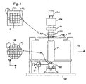
- Figure 1 schematically depicts a lithographic projection apparatus according to a particular embodiment of the invention.
- the apparatus comprises:
- the source LA (e.g. a laser-produced or discharge plasma source) produces a beam of radiation.
- This beam is fed into an illumination system (illuminator) IL, either directly or after having traversed conditioning means, such as a beam expander Ex, for example.
- the illuminator IL may comprise adjusting means AM for setting the outer and/or inner radial extent (commonly referred to as ⁇ -outer and ⁇ -inner, respectively) of the intensity distribution in the beam.
- ⁇ -outer and ⁇ -inner commonly referred to as ⁇ -outer and ⁇ -inner, respectively
- it will generally comprise various other components, such as an integrator IN and a condenser CO.
- the beam PB impinging on the mask MA has a desired uniformity and intensity distribution in its cross-section.
- the source LA may be within the housing of the lithographic projection apparatus (as is often the case when the source LA is a mercury lamp, for example), but that it may also be remote from the lithographic projection apparatus, the radiation beam which it produces being led into the apparatus (e.g. with the aid of suitable directing mirrors); this latter scenario is often the case when the source LA is an excimer laser.
- the current invention and Claims encompass both of these scenarios.
- the beam PB subsequently intercepts the mask MA, which is held on a mask table MT. Having been selectively reflected by the mask MA, the beam PB passes through the lens PL, which focuses the beam PB onto a target portion C of the substrate W. With the aid of the second positioning means (and interferometric measuring means IF), the substrate table WT can be moved accurately, e.g. so as to position different target portions C in the path of the beam PB. Similarly, the first positioning means can be used to accurately position the mask MA with respect to the path of the beam PB, e.g. after mechanical retrieval of the mask MA from a mask library, or during a scan.
- the mask table MT may just be connected to a short stroke actuator, or may be fixed.
- the depicted apparatus can be used in two different modes:
- Figure 2 illustrates a current amplifier and control system for a single-phase actuator 10, for example a single phase motor, according to an embodiment of the present invention.
- Actuator 10 is attached to the wafer table WT.
- the system of Figure 2 is duplicated for each further actuator attached to the wafer table WT. It may also be duplicated to supply the actuators of the mask table MT if that is movable.
- a motion controller calculates the setpoint current I s using the desired position, velocity and acceleration of the Wafer Table WT and the measured position.
- the method of calculating I s is the same as that described above in the discussion of the prior art with reference to Figure 5.
- the current meter 12 measures the present value I m of the current through the actuator 10. I m is then subtracted from the setpoint current I s by the mixer 2 to give an error value. This error value is then supplied as the input to the current controller 4.
- the current controller 4 uses control algorithm to determine the value of voltage to be supplied to the actuator in order to reach the setpoint current I s . In this embodiment the control algorithm used is PID, but others such as fuzzy logic or proportional-integral could also be used.
- An amplifier 6 is then used to supply this voltage to the actuator 10.
- the current controller 4 is implemented in a programmable DSP, microprocessor, microcontroller or any other type of digital controller and forms part of the overall motion controller. The current controller 4 could also be constructed from discrete components.
- a feedforward voltage U ff is also calculated by the motion controller and is added to the output of amplifier 6 by the mixer 8. The resultant voltage is then applied to the actuator 10. The process is repeated continuously as I s varies according to the desired movements.
- the feedforward voltage U ff calculated in this embodiment comprises three individual components: velocity v ff , acceleration a ff and jerk j ff (jerk is the derivative of acceleration).
- a flow chart showing calculation of the feedforward components is given in Figure 3.
- Calculation of the feedforward voltage requires knowledge of several variables.
- the setpoint generator provides the desired velocity, acceleration and jerk. Additionally the moving mass and four actuator characteristics (back-emf, resistance, self-inductance, and the reciprocal of the motor constant) are stored in the motion controller. These stored values may be updated dynamically as the behavior of the system in use is monitored or calibrated periodically.
- the desired values are determined by the setpoint generator according to the movement required and permitted maximum values. During operation it is likely that there will be a maximum acceleration or velocity which cannot be exceeded to avoid risk of damage, etc. These maximums form the constraints that limit the response of the system. For example the maximum value of acceleration will impose a limit on how quickly a given velocity can be achieved.
- the velocity feedforward v ff is calculated by multiplying the actuator back-emf and the desired velocity together (illustrated by multiplier 14).
- the acceleration feedforward a ff is calculated by multiplying the desired acceleration, actuator resistance, moving mass and reciprocal of the actuator motor constant together (illustrated by multiplier 16).
- the jerk feedforward j ff is calculated by multiplying the desired jerk, moving mass, actuator phase self inductance and reciprocal of the actuator motor constant together (illustrated by multiplier 18).
- the voltage across a coil in the actuator comprises three components:
- U is the coil voltage
- I is the actuator current
- R is the resistance
- L is the self inductance of the actuator
- t time
- B emf is the back-emf
- V is the velocity.
- J d is the desired jerk.
- the use of a voltage feedforward value improves the response and accuracy of the system with little extra cost.
- the calculation of the feedforward value is relatively simple and uses readily available data so the controller can be improved with little increase in complexity.
- the limiting factor on the response is now determined by the feedforward value and not the bandwidth of the current control loop. This leads to a faster response with less phase difference.
- FIG. 4 A second embodiment of the present invention is illustrated in Figure 4. The construction of this embodiment is as for the first embodiment save as described below.
- the single-phase actuator of the first embodiment is replaced with a multi-phase actuator 11, for example a three-phase motor.
- Each phase of the actuator 11 has a corresponding control system as illustrated in Figure 6.
- Each control system is as for the first embodiment with the addition of a current commutator 3 and a voltage commutator 7.
- Current commutator 3 has an input of the current setpoint Is and position dependent commutation phase information ⁇ .
- Voltage commutator 7 has an input of the voltage feedforward U ff and position dependent commutation phase information ⁇ .
- the position dependent commutation phase information ⁇ represents the magnetic phase that the coil is experiencing (this is dependent on position).
- the current setpoint and the voltage feedforward value are calculated in the same way as for the above described first embodiment. However, this only gives an output of the amplitude required, and does not consider the phase.
- the current commutator 3 converts the current setpoint I s from the motion controller into the correct value for that phase, using the position dependent commutation phase information ⁇ . Operation of the voltage commutator 7 is similar for calculating the voltage feedforward for the phase. However, this calculation must also consider that not all of the components in the voltage feedforward will vary with the magnetic phase the coil is experiencing, and so not all the components will need to be commutated.
- feedforward control with a multi-phase actuator having an arbitrary number of phases. Very little increase in complexity over the single-phase situation of the first embodiment is required. Furthermore, each calculation of current set-point and voltage feedforward need only be done once, there is no need to repeat it for each phase.
Landscapes
- Engineering & Computer Science (AREA)
- Physics & Mathematics (AREA)
- General Physics & Mathematics (AREA)
- Human Computer Interaction (AREA)
- Manufacturing & Machinery (AREA)
- Automation & Control Theory (AREA)
- Exposure And Positioning Against Photoresist Photosensitive Materials (AREA)
Priority Applications (1)
| Application Number | Priority Date | Filing Date | Title |
|---|---|---|---|
| EP04252492A EP1480093A1 (de) | 2003-05-13 | 2004-04-29 | Steuerungssystem, lithographisches Gerät, Verfahren zur Herstellung eines Gerätes und hiermit hergestelltes Gerät |
Applications Claiming Priority (3)
| Application Number | Priority Date | Filing Date | Title |
|---|---|---|---|
| EP03252965 | 2003-05-13 | ||
| EP03252965 | 2003-05-13 | ||
| EP04252492A EP1480093A1 (de) | 2003-05-13 | 2004-04-29 | Steuerungssystem, lithographisches Gerät, Verfahren zur Herstellung eines Gerätes und hiermit hergestelltes Gerät |
Publications (1)
| Publication Number | Publication Date |
|---|---|
| EP1480093A1 true EP1480093A1 (de) | 2004-11-24 |
Family
ID=33099714
Family Applications (1)
| Application Number | Title | Priority Date | Filing Date |
|---|---|---|---|
| EP04252492A Withdrawn EP1480093A1 (de) | 2003-05-13 | 2004-04-29 | Steuerungssystem, lithographisches Gerät, Verfahren zur Herstellung eines Gerätes und hiermit hergestelltes Gerät |
Country Status (1)
| Country | Link |
|---|---|
| EP (1) | EP1480093A1 (de) |
Cited By (3)
| Publication number | Priority date | Publication date | Assignee | Title |
|---|---|---|---|---|
| US7818073B2 (en) * | 2006-04-20 | 2010-10-19 | Asml Netherlands B.V. | Method for obtaining improved feedforward data, a lithographic apparatus for carrying out the method and a device manufacturing method |
| EP4394502A1 (de) * | 2022-12-27 | 2024-07-03 | ASML Netherlands B.V. | Verfahren zur erzeugung eines beschleunigungssollwertprofils für ein bewegliches objekt, sollwertgenerator und lithografische vorrichtung |
| CN119171795A (zh) * | 2024-08-23 | 2024-12-20 | 中国科学院长春光学精密机械与物理研究所 | 一种永磁同步电机的自抗扰控制方法及系统 |
Citations (5)
| Publication number | Priority date | Publication date | Assignee | Title |
|---|---|---|---|---|
| US4902944A (en) * | 1986-11-20 | 1990-02-20 | Staubli International Ag. | Digital robot control having an improved current sensing system for power amplifiers in a digital robot control |
| US4990001A (en) * | 1990-01-22 | 1991-02-05 | Losic Novica A | Synthesis of drive systems of infinite disturbance rejection ratio and zero-dynamics/instantaneous response |
| EP1265104A1 (de) * | 2001-06-06 | 2002-12-11 | ASML Netherlands B.V. | Lithographischer Apparat, Verfahren zur Herstellung eines Artikels und dabei erzeugter Artikel |
| EP1267213A1 (de) * | 2001-06-13 | 2002-12-18 | ASML Netherlands B.V. | Lithographischer Projektionsapparat |
| EP1347337A2 (de) * | 2002-03-18 | 2003-09-24 | Nikon Corporation | Kompensation für Kabelwiderstandskräfte, die auf eine Hochpräzisionsträgerplatte wirken |
-
2004
- 2004-04-29 EP EP04252492A patent/EP1480093A1/de not_active Withdrawn
Patent Citations (5)
| Publication number | Priority date | Publication date | Assignee | Title |
|---|---|---|---|---|
| US4902944A (en) * | 1986-11-20 | 1990-02-20 | Staubli International Ag. | Digital robot control having an improved current sensing system for power amplifiers in a digital robot control |
| US4990001A (en) * | 1990-01-22 | 1991-02-05 | Losic Novica A | Synthesis of drive systems of infinite disturbance rejection ratio and zero-dynamics/instantaneous response |
| EP1265104A1 (de) * | 2001-06-06 | 2002-12-11 | ASML Netherlands B.V. | Lithographischer Apparat, Verfahren zur Herstellung eines Artikels und dabei erzeugter Artikel |
| EP1267213A1 (de) * | 2001-06-13 | 2002-12-18 | ASML Netherlands B.V. | Lithographischer Projektionsapparat |
| EP1347337A2 (de) * | 2002-03-18 | 2003-09-24 | Nikon Corporation | Kompensation für Kabelwiderstandskräfte, die auf eine Hochpräzisionsträgerplatte wirken |
Cited By (4)
| Publication number | Priority date | Publication date | Assignee | Title |
|---|---|---|---|---|
| US7818073B2 (en) * | 2006-04-20 | 2010-10-19 | Asml Netherlands B.V. | Method for obtaining improved feedforward data, a lithographic apparatus for carrying out the method and a device manufacturing method |
| EP4394502A1 (de) * | 2022-12-27 | 2024-07-03 | ASML Netherlands B.V. | Verfahren zur erzeugung eines beschleunigungssollwertprofils für ein bewegliches objekt, sollwertgenerator und lithografische vorrichtung |
| WO2024141209A1 (en) * | 2022-12-27 | 2024-07-04 | Asml Netherlands B.V. | Method to generate an acceleration setpoint profile for a movable object, setpoint generator and lithographic apparatus |
| CN119171795A (zh) * | 2024-08-23 | 2024-12-20 | 中国科学院长春光学精密机械与物理研究所 | 一种永磁同步电机的自抗扰控制方法及系统 |
Similar Documents
| Publication | Publication Date | Title |
|---|---|---|
| US7061587B2 (en) | Control system, lithographic apparatus, device manufacturing method, and device manufactured thereby | |
| US7209219B2 (en) | System for controlling a position of a mass | |
| KR100547438B1 (ko) | 리소그래피장치 및 디바이스제조방법 | |
| JP2003115450A (ja) | リトグラフ装置、デバイス製造方法、およびその方法により製造されたデバイス | |
| US7098990B2 (en) | Lithographic apparatus, device manufacturing method, and device manufactured thereby | |
| EP1477861A1 (de) | Verfahren zur Eichung eines lithographischen Geräts, Ausrichtverfahren, Komputerprogramm, lithographisches Gerät und Verfahren zur Herstellung einer Vorrichtung | |
| US7170580B2 (en) | Lithographic apparatus, projection system, method of projecting and device manufacturing method | |
| EP1469348B1 (de) | Projektionssystem und Verfahren zu dessen Verwendung | |
| JP3940329B2 (ja) | リソグラフィ投影装置、デバイス製造方法 | |
| EP1480093A1 (de) | Steuerungssystem, lithographisches Gerät, Verfahren zur Herstellung eines Gerätes und hiermit hergestelltes Gerät | |
| US7280182B2 (en) | Lithographic apparatus, device manufacturing method and computer program | |
| US7657334B2 (en) | Lithographic apparatus and control method | |
| US6992752B2 (en) | Lithographic projection apparatus, computer program for control thereof, and device manufacturing method | |
| US20020018194A1 (en) | Lithographic projection apparatus and device manufacturing method | |
| EP1517187A2 (de) | Lithographischer Apparat, Verfahren zur Herstellung einer Vorrichtung und damit erzeugte Vorrichtung | |
| EP1455231A2 (de) | Kontrolle einer Position einer Masse, besonders in einem lithographischen Apparat | |
| JP4070751B2 (ja) | リソグラフィック装置およびデバイス製造方法 | |
| US7294844B2 (en) | Lithographic apparatus, device manufacturing method, and device manufactured thereby | |
| EP1267213A1 (de) | Lithographischer Projektionsapparat |
Legal Events
| Date | Code | Title | Description |
|---|---|---|---|
| PUAI | Public reference made under article 153(3) epc to a published international application that has entered the european phase |
Free format text: ORIGINAL CODE: 0009012 |
|
| AK | Designated contracting states |
Kind code of ref document: A1 Designated state(s): AT BE BG CH CY CZ DE DK EE ES FI FR GB GR HU IE IT LI LU MC NL PL PT RO SE SI SK TR |
|
| AX | Request for extension of the european patent |
Extension state: AL HR LT LV MK |
|
| 17P | Request for examination filed |
Effective date: 20050117 |
|
| AKX | Designation fees paid |
Designated state(s): DE FR GB IT NL |
|
| 17Q | First examination report despatched |
Effective date: 20071127 |
|
| STAA | Information on the status of an ep patent application or granted ep patent |
Free format text: STATUS: THE APPLICATION IS DEEMED TO BE WITHDRAWN |
|
| 18D | Application deemed to be withdrawn |
Effective date: 20091103 |