EP1480165A2 - Bildverarbeitung unter Nutzung von Information eines Bildaufnahmeprotokolls - Google Patents
Bildverarbeitung unter Nutzung von Information eines Bildaufnahmeprotokolls Download PDFInfo
- Publication number
- EP1480165A2 EP1480165A2 EP04012088A EP04012088A EP1480165A2 EP 1480165 A2 EP1480165 A2 EP 1480165A2 EP 04012088 A EP04012088 A EP 04012088A EP 04012088 A EP04012088 A EP 04012088A EP 1480165 A2 EP1480165 A2 EP 1480165A2
- Authority
- EP
- European Patent Office
- Prior art keywords
- image
- generating device
- image data
- brightness
- return
- Prior art date
- Legal status (The legal status is an assumption and is not a legal conclusion. Google has not performed a legal analysis and makes no representation as to the accuracy of the status listed.)
- Withdrawn
Links
Images




Classifications
-
- H—ELECTRICITY
- H04—ELECTRIC COMMUNICATION TECHNIQUE
- H04N—PICTORIAL COMMUNICATION, e.g. TELEVISION
- H04N1/00—Scanning, transmission or reproduction of documents or the like, e.g. facsimile transmission; Details thereof
- H04N1/40—Picture signal circuits
- H04N1/407—Control or modification of tonal gradation or of extreme levels, e.g. background level
- H04N1/4076—Control or modification of tonal gradation or of extreme levels, e.g. background level dependent on references outside the picture
Definitions
- the present invention relates to an image processing technology that uses image generation record information.
- JP11-069372A discloses an image processing technology whereby a brightness histogram is created for the whole image and the brightness is corrected such that a prescribed percentage of pixels exhibit the maximum brightness value.
- JP2000-057335A discloses another technology whereby an image is divided into several regions, and a brightness histogram is created from the image regions, and brightness correction is performed for each separate image region via analysis.
- An object of the present invention is to provide a technology that allows the brightness of an image to be corrected properly when it can be inferred that the user's desire is to increase image brightness.
- a device for processing an image file that includes image data generated by an image generating device that incorporates a flash unit, wherein the image file includes return information that, when the flash unit has been used, indicates whether or not the light emitted therefrom has reflected off the photo subject and returned to the image generating device.
- the image processing device includes a brightness correction module that corrects the image data using different brightness correction amounts that differ depending on whether a first condition exists wherein the return information indicates that the emitted light did not return to the image generating device, or whether a second condition exists wherein the return information indicates that the emitted light returned to the image generating device.
- the image processing device because it can be determined from the return information whether or not the image data brightness is sufficient, the image brightness can be corrected properly depending on whether or not the light returned to the image generating device.
- the present invention may be realized in various forms, and may be realized in such forms as an image processing device, an image processing method, a computer program for implementing the image processing method, a recording medium on which such computer program is recorded, and an image generation device comprising the image processing device.
- Fig. 1 is a block diagram showing the configuration of an image processing device
- Fig. 2 shows the configuration of a image file
- Fig. 3 shows the tag numbers, tag names and descriptions used in the Exif file format
- Fig. 4 shows the details of flash information
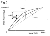
- Fig. 5 shows a brightness correction curve in a first embodiment
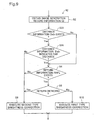
- Fig. 6 shows the processing routine executed by the brightness correction module of the first embodiment
- Fig. 7 shows the brightness correction curve in a second embodiment
- Fig. 8 shows the processing routine executed by the brightness correction module of a second embodiment
- Fig. 9 shows the processing routine executed by the brightness correction module of a third embodiment
- a digital still camera (hereinafter termed 'digicam') 12 includes a strobe 13 and a sensor 14.
- the sensor 14 detects whether or not the light emitted from the strobe 13 returned to the digicam 12 after reflecting off of the photo subject (i.e., whether or not return has occurred).
- the image generation record information that includes whether or not return has occurred is stored in the digicam 12 together with the image data generated thereby as a image file GF.
- the image file GF will be described below.
- the image file GF generated by the digicam 12 is input to the computer 80 by an application program 86 via a digicam driver 88.
- the application program 86 performs desired processing of the image file GF input to the computer 80 and displays an image on a CRT 22 via a video driver 84.
- a print data file PD to be forwarded to the printer 20 is output via a printer driver 90 from the image file GF.
- the printer driver 90 of the computer 80 receives the image file GF from the application program 86 and converts it into print data PD to be supplied to the printer 20.
- the printer driver 90 includes a brightness correction module 92, a resolution conversion module 96, a color conversion module 97, a halftone module 98 and a rasterizer 99.
- the brightness correction module 92 includes a brightness correction curve 94 with which the brightness value of the image data generated by the digicam 12 is corrected.
- the brightness correction module 92 converts the image data generated by the digicam 12 into image signals (RGB signals) having the desired brightness value with reference to the brightness correction curve 94.
- RGB signals The operations performed by the brightness correction module 92 will be described below.
- the RGB signals obtained via the conversion are input to the resolution conversion module 96.
- the brightness correction module 92 may be incorporated in the application program 86.
- the resolution conversion module 96 executes the function of converting the image data resolution into a printing resolution.
- the resolution-converted image data still constitutes image information comprising the three RGB color components, and becomes the input data for the color conversion module 97.
- the color conversion module 97 includes a color conversion lookup table LUT that specifies the relationship between image information comprising the three RGB color components and ink amount information regarding the inks available in the printer 20.
- the color conversion module 97 converts the RGB image data for each pixel into multiple-tone ink amount data with reference to the color conversion lookup table LUT. For example, where the four ink colors of yellow (Y), cyan (C), magenta (M) and black (K) can be used by the printer 20, the RGB image data is converted into YMCK multiple-tone data. The YMCK multiple-tone data obtained via this color conversion becomes input data for the halftone module 98.
- the YMCK multiple-tone data obtained via color conversion has 256 tones for each ink color, for example.
- the halftone module 98 executes so-called halftone processing for each ink color and generates halftone image data.
- This halftone image data is rearranged in order of data to be forwarded to the printer 20 by the rasterizer 99, and is output as final print data PD.
- the print data PD includes raster data indicating the state of dot formation during each main scan and data indicating the amount of sub-scanning to be performed.
- the printer driver 90 is a program that performs the functions of executing various image processes and generating the print data PD.
- the program that performs the functions of the printer driver 90 may be provided over electric communication circuits or in the form of a recording on a computer-readable recording medium.
- the recording medium may comprise any of various types of computer-readable recording media, such as a flexible disk, CD-ROM, opto-magnetic disk, IC card, ROM cartridge, punch card, printed matter on which symbols such as a bar code are printed, an internal computer storage medium (memory such as a RAM or ROM) or an external storage medium.
- GI image generation record information
- GI digital still camera image file format standard Exif (hereinafter termed 'Exif') established by the Japan Electronic Industry Development Association.
- Fig. 3 is a table listing tag numbers, tag names, and tag meanings used by Exif format.
- a tag number is the number for a tag indicated by a tag name, and in Fig. 3, the mark '.H' is appended to indicate the hexadecimal numbering system.
- the 'photo subject distance SD' tag is an integer having a tag number of '9206.H' and indicating the distance to the photo subject
- the 'flash' tag is an integer having a tag number of '9209.H' and indicating information regarding the flash unit
- the 'flash intensity' tag is an integer having a tag number of 'A20B.H' and indicating the intensity or energy of the flash light.
- the 'photo subject distance range SDR' tag has a tag number of 'A40C.H'.
- the 'photo subject distance range SDR' tag consists of photo subject distance category information.
- the photo subject distance range SDR tag is '1', indicating the macro mode, where the photo subject distance is a close distance, such as 1 to 3 meters, the photo subject distance range SDR tag is '2', where the photo subject distance is a far distance, such as 3 meters or more, the photo subject distance range SDR tag is '3', and where the photo subject distance is unknown, the photo subject distance range SDR tag is '0'.
- Fig. 4 shows detailed information regarding the 'flash' tag having a tag number of 9209.H.
- the numbers 0 through 7 indicate bit orders beginning with the least significant bit LSB, where 7 is the most significant bit MSB.
- the least significant bit LSB is used for flash use information USFL indicating whether or not the strobe 13 emitted light, and is '0' where the strobe 13 has not emitted light and '1' where the strobe 13 emitted light.
- Bits 2 and 3 are used for return information RNFL indicating whether or not the light emitted from the strobe 13 returned from the photo subject to the digicam 12.
- bit value is 00b, where such light detection function does exist but light return was not detected, the bit value is 10b, and where light return was detected, the value is 11b.
- the 'b' is a letter indicating that the value is expressed in the binary number system, such that where the value is 10b, for example, bit 2 is '1' and bit 1 is '0'.
- the image file GF generated by the digicam 12 can include photo subject distance SD or photo subject distance range SDR comprising distance information, flash use information USFL and return information RNFL.
- the brightness correction module 92 corrects the image data GD to a desired brightness using some of these items of information.
- the reason that the correction amount ⁇ NW is larger than the correction amount ⁇ OL is that the subject of the image data has sufficient brightness when the return information RNFL indicates that the light from the strobe 13 returned to the digicam 12, while it lacks sufficient brightness when the flash use information USFL indicates that the strobe 13 emitted light and the return information RNFL indicates that the light from the strobe 13 did not return to the digicam 12. In the latter case, because the sensor 14 cannot detect light reflected from the photo object regardless of the user's desire to use the strobe 13 to increase the brightness, the image data GD is dark.
- the correction amount ⁇ NW is increased. to be larger than the correction amount ⁇ OL in order to make the image data GD brighter.
- the correction amount ⁇ OL need not be a positive value, and may be zero. In other words, the image data GD may be used as the brightness value without correction when the return information RNFL indicates that that the light from the strobe 13 returned to the digicam 12.
- Fig. 6 shows the processing routine executed by the brightness correction module 92 of the first embodiment.
- the image generation record information GI is obtained from the image file GF.
- the brightness correction module 92 advances to step S8.
- step S8 a second type brightness correction is carried out in order to obtain a brightness value using the curve CvOd described in connection with Fig. 5.
- the flash use information USFL indicates that the strobe 13 was used and return information RNFL does exist
- the brightness correction module 92 advances to step S6.
- step S6 it is determined whether or not the return information RNFL indicates that the light emitted from the strobe 13 reflected off the photo subject and returned to the digicam 12. If the light from the strobe 13 returned to the digicam 12, the brightness correction module 92 advances to step S8. If the light from the strobe 13 did not return to the digicam 12, the brightness correction module 92 advances to step S10. In step S10, a first type brightness correction is carried out in order to obtain a brightness value using the curve CvNw described in connection with Fig. 5 in order to make the image data GD brighter.
- the desire of the user to increase the brightness of the image data GD can be inferred from the value of the flash use information USFL and it can be determined from the return information RNFL whether or not the brightness of the image data GD is sufficient, as described above. If the image data GD is insufficiently bright, the image data GD is corrected to a higher brightness value in accordance with the curve CvNw1 in the brightness correction module 92.
- the brightness value for the image data GD is obtained in accordance with the curve CvNw2 shown in Fig. 7, while in all other cases, the brightness value is obtained in accordance with the curve CvOd.
- the desire of the user to increase the brightness of the image data GD can be inferred from the value of the flash use information USFL and it can be determined from the return information RNFL whether or not the brightness of the image data GD is sufficient, as described above. If the image data GD is insufficiently bright, it is possible to increase in brightness only the brighter areas of the image data GD in accordance with the curve CvNw2 in the brightness correction module 92.
- the desire of the user to increase the brightness of the image data GD can be inferred from the value of the flash use information USFL and it can be determined from the return information RNFL whether or not the brightness of the image data GD is sufficient, as described above. If the image data GD is insufficiently bright, it is possible to increase in brightness only the relatively bright areas of the image data GD in accordance with the curves CvNw1 or CvNw2.
- the distance information DsIn is the photo subject distance SD and photo subject distance range SDR described in connection with Fig. 3.
- the photo subject distance SD is information expressing the distance to the photo subject in meters
- the photo subject distance range SDR is information expressing the distance to the photo subject in terms of 'close', 'far', 'macro' or 'unknown'.
- the photo subject distance SD is deemed a 'far' distance.
- the distance that is effectively covered by the strobe 13 integrated into the digicam 12 is generally around three meters or less. This distance is not limited to three meters, and it may be four meters or more if such distance is the distance at which the effect of the strobe 13 is lost. Furthermore, where a separate flash unit is used rather than the integrated strobe 13, the above distance may be the distance at which such separate flash unit is no longer effective, such as around 10 meters.
- the user's desire to increase the brightness of the image data GD is checked using the value of the flash use information USFL when the distance information DsIn indicates that the distance to the photo subject is a far distance.
- the distance information DsIn indicates that the distance to the photo subject is not a far distance
- brightness correction identical to that performed where the strobe 13 light has reflected off of the photo subject and returned to the digicam 12 is carried out.
- the desire of the user to increase the brightness of the image data GD can be inferred from the value of the flash use information USFL, and it can be determined from the return information RNFL whether or not the brightness of the image data GD is sufficient. If the image data GD is insufficiently bright, the brightness thereof can be corrected to a higher brightness level in accordance with the curve CvNw1 or the curve CvNw2.
- the amount of brightness correction of the image differs depending on whether a first condition is present in which flash light did not return to the digicam or whether a second condition is present in which flash light returned.
- This configuration offers the advantage of enabling the image to be corrected to the proper brightness in accordance with the existence of flash light return.
Landscapes
- Engineering & Computer Science (AREA)
- Multimedia (AREA)
- Signal Processing (AREA)
- Studio Devices (AREA)
- Image Processing (AREA)
- Television Signal Processing For Recording (AREA)
- Facsimile Image Signal Circuits (AREA)
- Exposure Control For Cameras (AREA)
- Stroboscope Apparatuses (AREA)
- Processing Or Creating Images (AREA)
Applications Claiming Priority (2)
| Application Number | Priority Date | Filing Date | Title |
|---|---|---|---|
| JP2003146135 | 2003-05-23 | ||
| JP2003146135A JP3835433B2 (ja) | 2003-05-23 | 2003-05-23 | 画像生成履歴情報を用いた画像処理 |
Publications (2)
| Publication Number | Publication Date |
|---|---|
| EP1480165A2 true EP1480165A2 (de) | 2004-11-24 |
| EP1480165A3 EP1480165A3 (de) | 2009-09-09 |
Family
ID=33095483
Family Applications (1)
| Application Number | Title | Priority Date | Filing Date |
|---|---|---|---|
| EP04012088A Withdrawn EP1480165A3 (de) | 2003-05-23 | 2004-05-21 | Bildverarbeitung unter Nutzung von Information eines Bildaufnahmeprotokolls |
Country Status (4)
| Country | Link |
|---|---|
| US (1) | US20050012849A1 (de) |
| EP (1) | EP1480165A3 (de) |
| JP (1) | JP3835433B2 (de) |
| CN (1) | CN100337466C (de) |
Families Citing this family (1)
| Publication number | Priority date | Publication date | Assignee | Title |
|---|---|---|---|---|
| CN101771826B (zh) * | 2008-12-29 | 2011-09-14 | 华晶科技股份有限公司 | 数字摄像装置及其亮度校正方法 |
Family Cites Families (9)
| Publication number | Priority date | Publication date | Assignee | Title |
|---|---|---|---|---|
| CA1320377C (en) * | 1988-04-15 | 1993-07-20 | Robert Paul Cloutier | Method and apparatus for detecting, recording and using scene information in a photographic system |
| US4998127A (en) * | 1989-07-31 | 1991-03-05 | Eastman Kodak Company | Camera with flash return sensing |
| JPH11119290A (ja) * | 1997-10-14 | 1999-04-30 | Sony Corp | 撮像装置 |
| JP3226520B1 (ja) * | 2000-03-21 | 2001-11-05 | オムロン株式会社 | 写真シール自動販売方法および写真シール自動販売機 |
| US6930718B2 (en) * | 2001-07-17 | 2005-08-16 | Eastman Kodak Company | Revised recapture camera and method |
| US7262798B2 (en) * | 2001-09-17 | 2007-08-28 | Hewlett-Packard Development Company, L.P. | System and method for simulating fill flash in photography |
| JP4294896B2 (ja) * | 2001-09-26 | 2009-07-15 | 富士フイルム株式会社 | 画像処理方法および装置並びにそのためのプログラム |
| JP3805259B2 (ja) * | 2002-01-29 | 2006-08-02 | 富士写真フイルム株式会社 | 画像処理方法、画像処理装置及び電子カメラ |
| JP2003244466A (ja) * | 2002-02-21 | 2003-08-29 | Konica Corp | 画像処理方法、画像処理装置、および画像記録装置 |
-
2003
- 2003-05-23 JP JP2003146135A patent/JP3835433B2/ja not_active Expired - Fee Related
-
2004
- 2004-05-19 CN CNB2004100446790A patent/CN100337466C/zh not_active Expired - Fee Related
- 2004-05-20 US US10/851,933 patent/US20050012849A1/en not_active Abandoned
- 2004-05-21 EP EP04012088A patent/EP1480165A3/de not_active Withdrawn
Also Published As
| Publication number | Publication date |
|---|---|
| JP3835433B2 (ja) | 2006-10-18 |
| CN100337466C (zh) | 2007-09-12 |
| JP2004350112A (ja) | 2004-12-09 |
| US20050012849A1 (en) | 2005-01-20 |
| EP1480165A3 (de) | 2009-09-09 |
| CN1574878A (zh) | 2005-02-02 |
Similar Documents
| Publication | Publication Date | Title |
|---|---|---|
| US5696594A (en) | Image forming method and apparatus for counterfeit protection controlling image synthesis in response to forming conditions | |
| US7903872B2 (en) | Image-processing apparatus and method, computer program, and storage medium | |
| US5289296A (en) | Color image processing apparatus and method | |
| JP4285127B2 (ja) | 減色処理装置及び減色処理方法 | |
| US7916352B2 (en) | Image processing apparatus, image processing method, program, and recording medium | |
| US20080239352A1 (en) | Image forming apparatus and control method thereof | |
| JP4280404B2 (ja) | 画像処理装置及びその方法 | |
| US6108098A (en) | Image processing apparatus and method | |
| US7253923B2 (en) | Image processing apparatus | |
| EP1480165A2 (de) | Bildverarbeitung unter Nutzung von Information eines Bildaufnahmeprotokolls | |
| JP3618776B2 (ja) | 画像処理装置及び方法 | |
| JP4295465B2 (ja) | 画像処理装置 | |
| JP4550727B2 (ja) | 画像処理装置及び画像形成装置 | |
| JPH08275010A (ja) | 画像処理方法及び装置 | |
| JP3039674B2 (ja) | カラー画像処理装置 | |
| JP4217302B2 (ja) | 画像処理装置及び画像処理方法 | |
| JPH06113113A (ja) | 画像形成装置 | |
| US20100091308A1 (en) | Image Processing Apparatus and Recording Medium | |
| JPH11177825A (ja) | 画像処理装置 | |
| US20250259029A1 (en) | Image processing apparatus, image processing method, and storage medium | |
| JPH0541796A (ja) | 複写装置 | |
| JP5225035B2 (ja) | 画像形成システム | |
| JP2001353935A (ja) | 画像処理の装置、システム及び方法 | |
| JP2500923B2 (ja) | カラ―画像変換方法 | |
| JP2005142740A (ja) | インクジェット原稿判別方法、画像処理装置、画像読取装置、画像形成装置、インクジェット原稿判別プログラム及び記録媒体 |
Legal Events
| Date | Code | Title | Description |
|---|---|---|---|
| PUAI | Public reference made under article 153(3) epc to a published international application that has entered the european phase |
Free format text: ORIGINAL CODE: 0009012 |
|
| AK | Designated contracting states |
Kind code of ref document: A2 Designated state(s): AT BE BG CH CY CZ DE DK EE ES FI FR GB GR HU IE IT LI LU MC NL PL PT RO SE SI SK TR |
|
| AX | Request for extension of the european patent |
Extension state: AL HR LT LV MK |
|
| PUAL | Search report despatched |
Free format text: ORIGINAL CODE: 0009013 |
|
| AK | Designated contracting states |
Kind code of ref document: A3 Designated state(s): AT BE BG CH CY CZ DE DK EE ES FI FR GB GR HU IE IT LI LU MC NL PL PT RO SE SI SK TR |
|
| AX | Request for extension of the european patent |
Extension state: AL HR LT LV MK |
|
| RIC1 | Information provided on ipc code assigned before grant |
Ipc: H04N 1/407 20060101ALI20090806BHEP Ipc: G06T 5/00 20060101AFI20040818BHEP |
|
| STAA | Information on the status of an ep patent application or granted ep patent |
Free format text: STATUS: THE APPLICATION HAS BEEN WITHDRAWN |
|
| 18W | Application withdrawn |
Effective date: 20091117 |