EP1480168B1 - Procédé et appareil de détection des yeux-rouges - Google Patents
Procédé et appareil de détection des yeux-rouges Download PDFInfo
- Publication number
- EP1480168B1 EP1480168B1 EP04011775A EP04011775A EP1480168B1 EP 1480168 B1 EP1480168 B1 EP 1480168B1 EP 04011775 A EP04011775 A EP 04011775A EP 04011775 A EP04011775 A EP 04011775A EP 1480168 B1 EP1480168 B1 EP 1480168B1
- Authority
- EP
- European Patent Office
- Prior art keywords
- red
- eye
- regions
- photographic image
- image
- Prior art date
- Legal status (The legal status is an assumption and is not a legal conclusion. Google has not performed a legal analysis and makes no representation as to the accuracy of the status listed.)
- Expired - Lifetime
Links
Images






Classifications
-
- G—PHYSICS
- G06—COMPUTING OR CALCULATING; COUNTING
- G06T—IMAGE DATA PROCESSING OR GENERATION, IN GENERAL
- G06T7/00—Image analysis
- G06T7/90—Determination of colour characteristics
-
- G—PHYSICS
- G06—COMPUTING OR CALCULATING; COUNTING
- G06V—IMAGE OR VIDEO RECOGNITION OR UNDERSTANDING
- G06V40/00—Recognition of biometric, human-related or animal-related patterns in image or video data
- G06V40/10—Human or animal bodies, e.g. vehicle occupants or pedestrians; Body parts, e.g. hands
- G06V40/16—Human faces, e.g. facial parts, sketches or expressions
- G06V40/161—Detection; Localisation; Normalisation
-
- G—PHYSICS
- G06—COMPUTING OR CALCULATING; COUNTING
- G06V—IMAGE OR VIDEO RECOGNITION OR UNDERSTANDING
- G06V40/00—Recognition of biometric, human-related or animal-related patterns in image or video data
- G06V40/10—Human or animal bodies, e.g. vehicle occupants or pedestrians; Body parts, e.g. hands
- G06V40/18—Eye characteristics, e.g. of the iris
- G06V40/193—Preprocessing; Feature extraction
-
- G—PHYSICS
- G06—COMPUTING OR CALCULATING; COUNTING
- G06T—IMAGE DATA PROCESSING OR GENERATION, IN GENERAL
- G06T2207/00—Indexing scheme for image analysis or image enhancement
- G06T2207/30—Subject of image; Context of image processing
- G06T2207/30216—Redeye defect
Definitions
- the present invention relates to a method and apparatus for detecting red-eye regions in a digital image according to the preamble of claims 1 and 13, respectively.
- Red-eye is a commonly occurring problem in flash photography, and typically occurs when the bright flash light of the camera is reflected from the blood vessels in the eye, giving the eye an unnatural red hue. Recognizing that the quality of photographs can be significantly improved if red-eyes can be fixed, research has focused on replacing red pixels with a more natural eye color once the image areas to be fixed have been indicated. If numerous images are to be processed in this manner, however, for example in a photofinishing lab, requiring an operator to examine each image and outline the red-eyes is difficult.
- Patent 6,278,491 the inventors of this application have found that techniques for improving detection speed and reducing the occurrence of false positives/negatives would significantly enhance the feasibility and quality of automatic red-eye detection and reduction, particularly in high volume operations such as a photofinishing lab.
- JP 06 258732 A discloses a method and an apparatus of automatically detecting red-eye regions in a photographic image. Using pattern recognition art, this document also shows the extraction of an outline of red-eye regions by distinguishing whether the outline is circular or not.
- the present invention is directed to a method and an apparatus for automatically detecting red-eye regions in a photographic image.
- a method of automatically detecting red-eye regions in a photographic image comprises the features of claim 1.
- an apparatus for automatically detecting red-eye regions in a photographic image comprises the features of claim 13.
- FIG. 1 is a block diagram of a system for automatic red-eye detection and correction according to an embodiment of the present invention
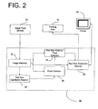
- FIG. 2 is a block diagram illustrating in more detail aspects of the image processing unit of the system illustrated in FIG. 1 according to an embodiment of the present invention
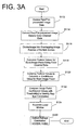
- FIG. 3A is a flow diagram illustrating operations performed by a red-eye candidate detection unit to detect the position of red-eye candidate regions according to an embodiment of the present invention
- FIG. 3B illustrates a technique for creating intermediate thresholds for early rejection during classification according to an embodiment of the present invention
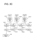
- FIG. 3C illustrates a technique for applying intermediate thresholds for early rejection during classification according to an embodiment of the present invention
- FIG. 4 illustrates an exemplary result of detecting the position of red-eye candidates according to implementation of the present invention
- FIG. 5 is a flow diagram illustrating operations performed by a face detection unit for eliminating red-eye candidates not associated with a detected face region according to an embodiment of the present invention
- FIG. 6 illustrates an exemplary output for the face detection unit according to an embodiment of the present invention
- FIG. 7 is a flow diagram illustrating operations of a red-eye outline detection unit according to an embodiment of the present invention.
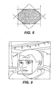
- FIG. 8 illustrates aspects of the operation for detecting a red-eye outline according to the operations illustrated in the flow diagram of FIG. 7 ;
- FIG. 9 illustrates an exemplary output of the red-eye outline detection unit according to an embodiment of the present invention.
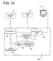
- FIG. 10 is a block diagram illustrating an alternative implementation for the image processing unit for the system illustrated in FIG. 1 ;
- FIG. 11 is a flow diagram illustrating operations performed by the complementary red-eye pixel detector in accordance with the implementation of the present invention illustrated in Fig. 10 .
- FIG. 12A illustrates an exemplary red-eye condition
- FIG. 12B illustrates an exemplary output of the red-eye pixel detection performed in accordance with the embodiment of the present invention illustrated in FIG. 10 .
- FIG. 1 illustrates a block diagram of a system for automatically detecting red-eye regions in a photographic image and for correcting red-eye regions according to an embodiment of the present invention.
- the system 100 illustrated in FIG. 1 includes the following components: an image input device 20; an image processing unit 30; a printing unit 40; a user input unit 50; and a display 60. Operation of and functional interaction between the components illustrated in FIG. 1 will become apparent from the following discussion.
- the image input device 20 provides digital image data representing a color photograph.
- the image input device 20 may be a scanner for scanning images recorded on film, e.g., including CCD sensors for photoelectronically reading R (red), G (green), and B (blue) image information from film, frame by frame.
- the image input device 20 may be one or more of any number of devices for providing digital image data derived from photographic film or a digital camera, e.g., a recording medium (a CD-R, floppy disk, etc.) or a network connection.
- the image processing unit 30 receives digital image data from the image input device 20 and performs red-eye detection and reduction in a manner discussed in detail below.
- a user may view outputs of image processing unit 30, including intermediate results of red-eye detection, via display 60 and may input commands to the image processing unit 30 via the user input device 50.
- the user input includes a keyboard 52 and a mouse 54.
- the image processing unit 30 may perform additional image processing functions, such as known color/density correction functions, as well as image cropping, compression, etc. in accordance with commands received from the user input device 50.
- the printing unit 40 receives the output of the image processing unit 30 and generates a hard copy of the processed image data.
- the printing unit 40 may expose a light-sensitive material according to image data output by the image processing unit 30 to record an image on the light-sensitive material.
- the printing unit 40 may take on other forms, such as a color laser printer.
- the processed image data may be returned to the customer as an image file, e.g., via a portable recording medium or via a network (not shown).
- FIG. 2 illustrates details of the image processing unit 30 for performing red-eye detection and reduction according to a first embodiment of the present invention.
- the image processing unit 30 includes: an image memory 32, which receives digital image data from the image input device 20; a red-eye candidate detector 34; a face detector 36; a red-eye outline/pixel detector 38; and a red-eye reduction module 39.
- an image memory 32 which receives digital image data from the image input device 20
- a red-eye candidate detector 34 receives digital image data from the image input device 20
- a red-eye candidate detector 34 receives digital image data from the image input device 20
- a red-eye candidate detector 34 e.g., a face detector 36
- a red-eye outline/pixel detector 38 e.g., a red-eye outline/pixel detector 38
- a red-eye reduction module 39 e.g., the arrangement of elements for the image processing unit 30 illustrated in FIG.
- red-eye candidate detection to find red-eye-like candidate image patches and face detection to eliminate false positives (i.e., image regions that look like possible red-eyes, but are not); and a red-eye outline/pixel detector that determines the red-eye outline and red-eye pixels within such an outline. Operation of the components of the image processing unit 30 illustrated in FIG. 2 will next be described with reference to FIGS. 3-9 .
- FIG. 3A is a flow diagram illustrating operations performed by the red-eye candidate detector 34 in accordance with an embodiment of the present invention.
- the red-eye candidate detector 34 accesses digital image data from the image memory 32 for the image being considered (S112).
- the image data received by the red-eye candidate detector 34 may be preprocessed, for example using local luminance equalization to enhance red-eye detection.
- local luminance equalization may be performed by normalizing each pixel using the average luminance for a rectangular (or some other shape) neighborhood around the pixel being normalized, for example by subtracting the average local luminance from the pixel being normalized or dividing the pixel being normalized by the average local luminance.
- known techniques for luminance adjustment can be applied.
- the red-eye candidate detector 34 When the image data received from the image memory 32 is R, G, B data, the red-eye candidate detector 34 performs color conversion to the YCbCr color space, which captures the illuminance, blueness, and redness measurements of each pixel (S114). Recognizing that the skin surrounding a red-eye often appears somewhat red or pink, an embodiment of the present application also uses an additional color channel, Cr * , that facilitates discrimination between red-eye and surrounding skin pixels. Such an auxiliary color channel is described in detail below with reference to the second embodiment of the present application.
- the input image data (e.g., 1200x1800 pixels) may be size adjusted (e.g., to 900x1350 pixels) to increase speed, more specifically so that the red-eye candidate detector 34 will not look for red-eyes that are too small.
- the red-eye candidate detector 34 divides the image into overlapping image patches of fixed size (e.g., 11x11 pixels) and multiple scales of such a fixed size (e.g., scaled by a factor of 2, 4, 8...) (S116), and calculates feature values for each image patch using the YCbCrCr* color channels. Scaling is performed since red-eyes may appear in a variety of sizes. Each calculated feature value uses pixel values from a particular color channel or a combination of color channels.
- fixed size e.g., 11x11 pixels
- scales of such a fixed size e.g., scaled by a factor of 2, 4, 8...)
- each feature value may be calculated by taking an average value of a color channel over a rectangular region (e.g., an entire 11x11 image patch or a sub-region of the patch), or by calculating a difference of such averages in two separate rectangular areas. It should be recognized that hundreds or even thousands of different feature values are possible.
- the red-eye candidate detector 34 determines whether a particular image patch represents a red-eye candidate by combining calculated feature values, thereby obtaining a classifier response ("confidence value") (S120), which is compared to a threshold value to either accept/reject the corresponding image patch as a red-eye candidate (S122).
- the feature values may be quantized (e.g., into 64 levels) and the threshold for accepting/rejecting red-eye candidates may be based on a histogram generated during a "learning" process (discussed in greater detail below). Having determined an initial set of red-eye candidate regions, the red-eye candidate detector 34 may perform post-processing, such as non-maximum suppression (i.e., keeping only local maximum of the classifier response) (S124) and outputs the position and scale of the remaining red-eye candidates (S126).
- post-processing such as non-maximum suppression (i.e., keeping only local maximum of the classifier response) (S124) and outputs the position and scale of the remaining red-eye candidates (S126).
- early rejection may be implemented, calculating intermediate classifier response values that are compared to intermediate thresholds, thereby allowing the system to quickly eliminate image patches as not corresponding to red-eye regions.
- This early rejection technique may prevent the occurrence of false negatives by using a training technique discussed below.
- Red-eyes are, essentially, small red circular blobs, but accurately and quickly identifying red-eyes presents challenges. Furthermore, if a red-eye detector is designed by hand, it is difficult to ensure that the detector is robust or applicable to many types of red-eye.
- One implementation of the present invention chooses the alternative: learning the detector automatically from data. In particular, sufficient quantities of ( positive ) example images of red-eyes, and ( negative ) examples of non-red-eye images are gathered. The training examples may be normalized to have a fixed size (re-scaling the red-eyes as necessary). Next, machine learning methods can be applied to train the classifier to distinguish between positive and negative data. Such a classifier looks at an image patch of a fixed size (e.g., 11x11 pixels) and determines whether or not it represents a red-eye.
- a fixed size e.g., 11x11 pixels
- Training the classifier for a set of positive and negative examples, is an iterative process where the weak classifiers f i are learned in a sequence, and the weights of the training examples are updated so that they are higher for the examples that are more difficult, i.e., those which are misclassified by the combination of the weak classifiers learned so far.
- f ( X i ) is high in magnitude and of the same sign as y i -- but this is impossible in practice because, for the classifier to generalize, the complexity of f(X) must be constrained.
- the image features used for red-eye and face detection (described below) can take on a finite number of values, and it is natural to consider weak classifiers that look at a single feature.
- each distribution is learned from a set of weighted examples and is represented with a histogram -- with a bin for each feature value x .
- each possible feature is tried, the corresponding weak classifier is computed, the resulting value of the objective function ⁇ is evaluated, and the feature for which ⁇ is the highest is selected.
- the red-eye detector 34 should have a very low false positive rate, since each photograph will contain a huge number of potential faces or red-eyes, at different positions and scales. Thus, it is preferable to have a large set of representative negative examples. However, the same set of training examples do not have to be used at all iterations of training. Instead, bootstrapping may be applied: after every few weak classifiers, the current state of the detector is known, which is applied to background images and the patterns falsely classified as positive are extracted. These false positives become the negative training set for the next several training iterations.
- the thresholds can be computed by analyzing a large number of positive training examples, and computing the thresholds ⁇ 1 ,..., ⁇ N one by one.
- ⁇ k is found by computing the intermediate classifier response f 1 X + ... + f K - 1 X for each example X , setting the response to - ⁇ if the example is rejected by any of the thresholds ⁇ 1 ,,, ⁇ K -1 . Then, ⁇ K is chosen so that the fraction of responses that are below ⁇ K is r K .
- the system can decide the order in which to apply the weak classifiers.
- the order of weak classifiers may be learned using boosting.
- the system could use the greedy search method to find the first weak classifier to use (and the corresponding threshold ⁇ 1 ) so as to maximize the number of rejected negative examples; the subsequent classifiers and thresholds being found similarly.
- FIG. 3B shows the flowchart for learning the intermediate thresholds in accordance with an implementation of the present invention.
- FIG. 3C shows how the intermediate thresholds may be used for early rejection.
- a plurality of training examples are input (S150), corresponding to red-eye regions of various size and non-red-eye regions, and a plurality of feature values, feature 1 - feature 4 in the example of FIG. 3B , are successively calculated (S152-1, S152-2, S152-3, S152-4).
- an accumulated response is generated for each feature value (S154-1, S154-2, S154-3, S154-4) to calculate a plurality of intermediate thresholds (S156-1, S156-2, S156-3, S156-4), which can subsequently be used for early rejection.
- FIG. 3C illustrates an exemplary implementation of using such intermediate thresholds.
- image data is input (S170) and a plurality of feature values, feature 1 - feature 4 in the example of FIG. 3C , are successively calculated (S172-1, S172-2, S172-3, S172-4).
- a response value for the input image data is successively calculated based on calculated feature values (S174-1, S174-2, S174-3, S174-4), and compared to a threshold so that the input data is rejected as red-eye candidate if the accumulated response falls below the previously-calculated intermediate threshold (S176-1, S176-2, S176-3).
- the steps of calculating additional feature values for a particular image region may be avoided if an intermediate response value falls below an intermediate threshold.
- FIG. 4 illustrates an exemplary result of the red-eye candidate detector 34, including a rectangle around remaining red-eye candidates.
- the red-eye candidate detector may include false-positives, such as lights having a hue/shape that may be confused with the red-eye region.
- the face detector 36 eliminates such false positives included in the set of red-eye candidates output by the red-eye candidate detector 34.
- FIG. 5 is a flow diagram illustrating operations performed by the face detector 36 in accordance with an embodiment of the present invention.
- the above-described techniques for training and early rejection may also be applied to face detection.
- the face detector 36 eliminates false positives by eliminating red-eye candidates not associated with a face.
- the face detector 36 accesses image data from the image memory 32 (S212) and receives red-eye candidates (position, scale) from the red-eye candidate detector 34 (S214).
- the face detector 36 only utilizes luminance values, Y, to perform face detection. Therefore, if the image data provided by the image memory 32 is RGB data, the face detector 36 transforms such data into a color space that includes the luminance, Y, channel for each pixel.
- the face detector 36 calculates feature values for scaled/rotated image regions containing a red-eye candidate as indicated by the red-eye candidate detector 34 (S216), such calculated feature values being compared to a threshold to identify the corresponding image patch as a face region or a non-face region (S218).
- the face detector 36 is able to eliminate red-eye candidates not associated with a detected face region (S220), and outputs the remaining red-eye candidates (S222).
- images for face detection are represented with quantized wavelet coefficients of the image luminance.
- the face detector 36 may compute the Discrete Wavelet Transform (DWT) of the luminance using a 5/3 filter bank, and keep only the HL and LH bands at 3 levels of decomposition (that is, using the responses to horizontal and vertical bar filters at 3 scales).
- DWT Discrete Wavelet Transform
- Face detection using DWT coefficients is known and described in H. Schneiderman et al., "A statistical method for 3d object detection applied to faces and cars," in IEEE Conf. on Computer Vision and Pattern Recognition, 2000, pp. 746-51 .
- the wavelet coefficients may be contrast-normalized using local image variance and quantized to 7 levels each.
- Each feature used for face detection may be a combination of 4 quantized DWT coefficients. Therefore, each candidate face image may be represented with a set of discrete features.
- the red-eye detection is faster (i.e., less computationally intensive) than face detection.
- the red-eyes (i) can be represented using smaller patches as compared to faces (e.g., 11x11 pixels for eyes vs. 31x28 pixels for faces), and (ii) are rotation invariant, and also more scale invariant than faces.
- faces e.g., 11x11 pixels for eyes vs. 31x28 pixels for faces
- ii) are rotation invariant, and also more scale invariant than faces.
- a single orientation of the image and scales spaced by a factor of 2 may be considered, whereas, for faces, 4 or 12 rotations of the image and scales spaced by a factor of 1.2 may be considered. Therefore, applying red-eye detection before face detection, and considering a candidate face only if a red-eye was detected nearby, significantly improves detection speed.
- the face detector 36 may be trained, using a set of positive images containing faces and negative images without faces.
- FIG. 6 illustrates an exemplary output of the face detector 36, which, as compared to FIG. 4 , has eliminated the false positives generated by the red-eye candidate detector 34.
- the red-eye outline/pixel detector 38 accurately determines the outline for the identified red-eye regions associated with a face and pixels within the detected outline.
- FIG. 7 is a flow diagram illustrating operations performed by the red-eye outline/pixel detector 38 according to an embodiment of the present invention.
- the red-eye outline/pixel detector 38 initially receives red-eye positions, scale information from the face detector 36 (S312), and accesses image data from image memory 32.
- the red-eye outline/pixel detector 38 calculates feature values for the identified red-eye image patches (S314).
- the red-eye outline/pixel detector 38 may be trained to respond to the edges of the red-eye region.
- the red-eye outline/pixel detector 38 is trained in accordance with an embodiment of the present invention to respond to the top edge of the red-eye, such that the top edge of the red-eye is detected from multiple rotations of the red-eye image patch (S316).
- the edge detector may be trained in a way identical to the red-eye detector 34, except for the geometric normalization of positive training examples. In other words, the same feature types may be used.
- the training red-eye examples were centered at the center of the image patch.
- Training the edge detector 38 each red-eye is rotated by a random angle and the upper-most point of the rotated red-eye is placed at the center of the image patch, thus ensuring that the detector is anchored to the edge rather than the center of the red-eye.
- the red-eye outline is detected and the red-eye pixels within the outline are output (S318). It should be recognized that fewer rotations (e.g., 6, 4, or 3 rotations) or a greater number of rotations may be used.
- the red-eye outline/pixel detector 38 may be used to eliminate additional false positives, e.g., based on a geometric analysis of the detected outline. For example, if the aspect ratio of the outline is not close to 1, the identified red-eye may be eliminated because red-eyes may be expected to be roughly circular in shape.
- FIG. 9 illustrates an exemplary output of the red-eye outline/pixel detector 38.
- the red-eye reduction module 39 may be incorporated to change the identified pixels within the red-eye outline to a more natural color. In this process, the red-eye reduction module 39 may choose a different color for different pixels or may substitute red-eye pixels with a predetermined value.
- FIG. 10 is a block diagram illustrating components of an image processing unit 30a in accordance with a second embodiment of the present invention.
- the image processing unit 36 includes the following elements: an image memory 32a; a red-eye candidate detector 34a; a face detector 36a; a red-eye outline/pixel detector 38a; a red-eye reduction module 39a; and a complementary red-eye pixel detector 35.
- the red-eye candidate detector 34a, the face detector 36a, and the red-eye outline/pixel detector 38a function in like manner to the corresponding elements of the first embodiment.
- the complementary red-eye pixel detector 35 further performs red-eye pixel detection, the results of which are combined with the output of the red-eye outline/pixel detector 38a to more accurately indicate pixels that should be subject to red-eye reduction processing by the red-eye reduction module 39a.
- FIG. 11 is a flow diagram illustrating operations performed by the complementary red-eye pixel detector 35 in accordance with an implementation of the present invention.
- the complementary red-eye pixel detector 35 effectively distinguishes red-eye pixels from surrounding pixels by converting image data into a color channel, Cr * , specifically designed to maximize differences between the red-eye pixels and surrounding pixels.
- the complementary red-eye pixel detector 35 accesses image data from the image memory 32a (S610), which is subsequently processed by dividing the image into regions.
- the object of interest i.e., a red-eye
- background regions may span a similar range of colors.
- the second embodiment of the present application automatically determines a feature to separate red-eye pixels from background pixels using training examples.
- object pixels of the input image are known.
- a sample is generated by normalizing its value by the background in the same image. Normalizing may be achieved by subtracting the mean value of the background from the object pixel. Alternatively, the object pixel value may be divided by the mean of the background.
- the normalized sample values are applied to a linear discriminant function, the Fisher linear discriminant according to an implementation of the present invention, thereby resulting a measure f that takes as input a normalized sample value and returns a value which reflects the confidence that the normalized sample value came from a red-eye.
- the pixel x is normalized based on the mean value of a neighborhood of x , such a neighborhood being designed so as to exclude most object pixels.
- the neighborhood is designed so that the range of colors in the neighborhood is coherent and as distinct as possible from the pixels of interest.
- the neighborhood can be the annulus around the red-eye area, which is expected to contain primarily skin.
- the end result of the complementary red-eye pixel detector 35 is a binary mask, identifying the red-eye pixels (S620).
- the output of the complementary red-eye pixel detector 35 is combined with the output of the red-eye outline/pixel detector 38a (as shown in the embodiment of FIG. 10 ) to improve detection accuracy.
- the color channel utilized by the complementary red-eye pixel detector 35 may be utilized by the red-eye candidate detector to improve detection therein and may be used as a preprocessing to reject uninteresting areas because it is fast to compute.
- FIG. 12A illustrates an example of a red-eye condition input to the complementary red-eye pixel detector 35
- FIG. 12B illustrates an exemplary binary mask (the hatched region representing red-eye pixels) output by the complementary red-eye pixel detector 35.
- One advantage of the complementary red-eye pixel detector 35 seen from FIG. 12B is that interior portions of the eye that are not negatively affected by the red-eye condition are separated from the surrounding red-eye portion, such that non-affected pixels within the eye are not subject to subsequent red-eye reduction, thus preserving a natural appearance in the end result.
Landscapes
- Engineering & Computer Science (AREA)
- General Physics & Mathematics (AREA)
- Physics & Mathematics (AREA)
- Theoretical Computer Science (AREA)
- General Health & Medical Sciences (AREA)
- Human Computer Interaction (AREA)
- Health & Medical Sciences (AREA)
- Multimedia (AREA)
- Computer Vision & Pattern Recognition (AREA)
- Oral & Maxillofacial Surgery (AREA)
- Ophthalmology & Optometry (AREA)
- Image Processing (AREA)
- Image Analysis (AREA)
- Facsimile Image Signal Circuits (AREA)
Claims (24)
- Procédé permettant de détecter automatiquement des régions d'oeil rouge dans une image photographique, ledit procédé comprenant :l'accès à des données d'image numérique représentant une image photographique couleur ;la détection de régions candidates d'oeil rouge dans ladite image photographique en traitant lesdites données d'image numérique, ladite étape de détection de régions candidates d'oeil rouge incluantle calcul de valeurs de caractéristique pour de multiples positions de ladite image photographique, etl'identification de régions candidates d'oeil rouge sur la base desdites valeurs de caractéristique calculées résultant de ladite étape de calcul ; etl'exécution d'une détection de visage afin de déterminer si une région candidate d'oeil rouge identifiée est associée à un visage,caractérisé en ce que l'étape de détection de régions candidates d'oeil rouge compare itérativement une valeur de réponse, calculée comme une combinaison de valeurs de caractéristique, pour une région d'image à des valeurs de seuil intermédiaires afin de réaliser un rejet précoce de régions d'image non associées à un oeil rouge,
dans lequel lesdits valeurs de seuil intermédiaires sont obtenues par l'intermédiaire d'une session d'apprentissage, en utilisant des images d'échantillon de régions d'image d'oeil rouge et sans oeil rouge, de taille et d'orientation diverse, en ce que l'étape d'exécution de détection de visage compare itérativement une valeur de réponse de détection de visage pour une région d'image à une valeur de seuil intermédiaire afin de réaliser un rejet précoce de régions d'image non associées à un visage, et
dans lequel lesdites valeurs de seuil intermédiaires sont obtenues par l'intermédiaire d'une session d'apprentissage, en utilisant des images d'échantillon de régions de visage et de non-visage, de taille et d'orientation diverse. - Procédé permettant de détecter automatiquement des régions d'oeil rouge dans une image photographique selon la revendication 1, dans lequel ladite étape d'exécution de détection de visage inclut
le calcul de valeurs de caractéristique pour ladite image photographique, et
la détermination de si une région candidate d'oeil rouge détectée est associée à un visage sur la base desdites valeurs de caractéristique. - Procédé permettant de détecter automatiquement des régions d'oeil rouge dans une image photographique selon la revendication 1, comprenant en outre :la détection d'un contour pour chaque région candidate d'oeil rouge identifiée associée à un visage.
- Procédé permettant de détecter automatiquement des régions d'oeil rouge dans une image photographique selon la revendication 1, comprenant en outre :la génération d'un masque de détection d'oeil rouge identifiant des pixels candidats d'oeil rouge dans ladite image photographique, incluant la conversion de données d'image de ladite image photographique couleur en un canal de couleur avec un contraste accru entre des pixels d'objet et des pixels d'arrière-plan local.
- Procédé permettant de détecter automatiquement des régions d'oeil rouge dans une image photographique selon la revendication 3, comprenant en outre :la génération d'un masque de détection d'oeil rouge identifiant des pixels candidats d'oeil rouge dans ladite image photographique, incluant la conversion de données d'image de ladite image photographique couleur en un canal de couleur avec un contraste accru entre des pixels d'objet et des pixels d'arrière-plan local ; etla combinaison des résultats de ladite étape de génération de masque de détection d'oeil rouge et de ladite étape de détection d'un contour afin d'identifier des pixels dans lesdites données d'image numérique devant être soumis à une réduction d'oeil rouge.
- Procédé permettant de détecter automatiquement des régions d'oeil rouge dans une image photographique selon la revendication 1, dans lequel ladite sous-étape de calcul de valeurs de caractéristique pour de multiples positions de ladite image photographique inclut la conversion de données d'image de ladite image photographique couleur en un canal de couleur avec un contraste accru entre des pixels d'objet et des pixels d'arrière-plan local.
- Procédé permettant de détecter automatiquement des régions d'oeil rouge dans une image photographique selon la revendication 1, dans lequel ladite sous-étape de calcul de valeurs de caractéristique pour de multiples positions de ladite image photographique calcule des valeurs de caractéristique à partir de données d'image Y, Cb et Cr.
- Procédé permettant de détecter automatiquement des régions d'oeil rouge dans une image photographique selon la revendication 1, dans lequel ladite sous-étape de calcul de valeurs de caractéristique pour de multiples positions de ladite image photographique est effectuée en scannant des données d'image photographique en utilisant une fenêtre de taille fixe et en répétant ledit scannage pour des versions à échelle modifiée de ladite image photographique, de sorte que ladite étape de détection de régions candidates d'oeil rouge identifie des régions candidates d'oeil rouge de diverses tailles.
- Procédé permettant de détecter automatiquement des régions d'oeil rouge dans une image photographique selon la revendication 1, dans lequel ladite sous-étape de calcul de valeurs de caractéristique calcule une pluralité de classifieurs faibles.
- Procédé permettant de détecter automatiquement des régions d'oeil rouge dans une image photographique selon la revendication 1, dans lequel ladite étape d'exécution de détection de visage calcule des coefficients de transformée en ondelettes discrète afin de distinguer des visages de non-visages.
- Procédé permettant de détecter automatiquement des régions d'oeil rouge dans une image photographique selon la revendication 3, dans lequel ladite étape de détection d'un contour pour une région candidate d'oeil rouge identifiée détecte un bord d'oeil rouge supérieur pour de multiples rotations de la région d'image correspondante.
- Procédé permettant de détecter automatiquement des régions d'oeil rouge dans une image photographique selon la revendication 1, dans lequel
ladite étape de détection de régions candidates d'oeil rouge génère un ensemble de régions candidates d'oeil rouge, et
ladite étape d'exécution de détection de visage élimine des candidats dudit ensemble de régions candidates d'oeil rouge trouvés comme n'étant pas associés à un visage. - Appareil pour détecter automatiquement des régions d'oeil rouge dans une image photographique, ledit appareil comprenant :une unité de données d'image (20) pour fournir des données d'image numérique représentant une image photographique couleur ;une unité de détection de candidat d'oeil rouge (34, 34a) pour détecter des régions candidates d'oeil rouge dans ladite image photographique en traitant lesdites données d'image numérique, ladite unité de détection de candidat d'oeil rouge (34, 34a) détectant des régions candidates d'oeil rouge encalculant des valeurs de caractéristique pour de multiples positions de ladite image photographique, etidentifiant des régions candidates d'oeil rouge sur la base desdites valeurs de caractéristique calculées ; etune unité de détection de visage (36, 36a) pour effectuer une détection de visage afin de déterminer si une région candidate d'oeil rouge détectée est associée à un visage,caractérisé en ce que ladite unité de détection de candidat d'oeil rouge (34, 34a) compare itérativement une valeur de réponse, calculée comme une combinaison de valeurs de caractéristique, pour une région d'image à des valeurs de seuil intermédiaires afin de réaliser un rejet précoce de régions d'image non associées à un oeil rouge,
dans lequel lesdites valeurs de seuil intermédiaires sont obtenues par l'intermédiaire d'une session d'apprentissage, en utilisant des images d'échantillon de régions d'image d'oeil rouge et sans oeil rouge, de taille et d'orientation diverse, et en ce que ladite unité de détection de visage (36) compare itérativement une valeur de réponse de détection de visage pour une région d'image à une valeur de seuil intermédiaire afin de réaliser un rejet précoce de régions d'image non associées à un visage,
dans lequel lesdites valeurs de seuil intermédiaires sont obtenues par l'intermédiaire d'une session d'apprentissage, en utilisant des images d'échantillon de régions de visage et de non-visage, de taille et d'orientation diverse. - Appareil selon la revendication 13, dans lequel ladite unité de détection de visage (36) effectue une détection de visage en
calculant des valeurs de caractéristique pour ladite image photographique, et
déterminant si une région candidate d'oeil rouge détectée est associée à un visage sur la base desdites valeurs de caractéristique. - Appareil selon la revendication 13, comprenant en outré :une unité de détection de contour d'oeil rouge (38, 38a) pour détecter un contour pour chaque région candidate d'oeil rouge identifiée associée à un visage.
- Appareil selon la revendication 13, comprenant en outre :une unité de détection de pixel d'oeil rouge complémentaire (35) pour générer un masque de détection d'oeil rouge identifiant des pixels candidats d'oeil rouge dans ladite image photographique, ladite unité de détection de pixel d'oeil rouge complémentaire (35) convertissant des données d'image de ladite image photographique couleur en un canal de couleur avec un contraste accru entre des pixels d'objet et des pixels d'arrière-plan local.
- Appareil selon la revendication 15, comprenant en outre :une unité de détection d'oeil rouge complémentaire (35) pour générer un masque de détection d'oeil rouge identifiant des pixels candidats d'oeil rouge dans ladite image photographique, ladite unité de détection de pixel d'oeil rouge complémentaire convertissant des données d'image de ladite image photographique couleur en un canal de couleur avec un contraste accru entre des pixels d'objet et des pixels d'arrière-plan local,dans lequel la sortie de ladite unité de détection d'oeil rouge complémentaire est combinée avec la sortie de ladite unité de détection de contour d'oeil rouge afin d'identifier des pixels dans lesdites données d'image numérique devant être soumis à une réduction d'oeil rouge.
- Appareil selon la revendication 13, dans lequel ladite unité de détection de candidat d'oeil rouge (34, 34a) convertit des données d'image de ladite image photographique couleur en un canal de couleur avec un contraste accru entre des pixels d'objet et des pixels d'arrière-plan local.
- Appareil selon la revendication 13, dans lequel ladite unité de détection de candidat d'oeil rouge calcule des valeurs de caractéristique à partir de données d'image Y, Cb et Cr.
- Appareil selon la revendication 13, dans lequel ladite unité de détection d'oeil rouge (34, 34a) scanne des données d'image photographique en utilisant une fenêtre de taille fixe et répète ledit scannage pour des versions à échelle modifiée de ladite image photographique, détectant ainsi des régions candidates d'oeil rouge de diverses tailles.
- Appareil selon la revendication 13, dans lequel ladite unité de détection d'oeil rouge (34, 34a) calcule lesdites valeurs de caractéristique comme une pluralité de classifieurs faibles.
- Appareil selon la revendication 13, dans lequel ladite unité de détection de visage (36, 36a) calcule des coefficients de transformée en ondelettes discrète afin de distinguer des visages de non-visages.
- Appareil selon la revendication 15, dans lequel ladite unité de détection de contour d'oeil rouge (38, 38a) détecte un bord d'oeil rouge supérieur pour de multiples rotations de la région d'image correspondante.
- Appareil selon la revendication 13, dans lequel
ladite unité de détection de candidat d'oeil rouge (34, 34a) génère un ensemble de régions candidates d'oeil rouge, et
ladite unité de détection de visage (36, 36a) effectue une détection de visage afin d'éliminer des candidats dudit ensemble de régions candidates d'oeil rouge trouvés comme n'étant pas associés à un visage.
Priority Applications (1)
| Application Number | Priority Date | Filing Date | Title |
|---|---|---|---|
| EP05027116A EP1653409B1 (fr) | 2003-05-19 | 2004-05-18 | Procédé et appareil pour la détection des yeux rouges |
Applications Claiming Priority (2)
| Application Number | Priority Date | Filing Date | Title |
|---|---|---|---|
| US440173 | 2003-05-19 | ||
| US10/440,173 US7343028B2 (en) | 2003-05-19 | 2003-05-19 | Method and apparatus for red-eye detection |
Related Child Applications (2)
| Application Number | Title | Priority Date | Filing Date |
|---|---|---|---|
| EP05027116A Division EP1653409B1 (fr) | 2003-05-19 | 2004-05-18 | Procédé et appareil pour la détection des yeux rouges |
| EP05027116.2 Division-Into | 2005-12-12 |
Publications (3)
| Publication Number | Publication Date |
|---|---|
| EP1480168A2 EP1480168A2 (fr) | 2004-11-24 |
| EP1480168A3 EP1480168A3 (fr) | 2005-01-19 |
| EP1480168B1 true EP1480168B1 (fr) | 2010-04-14 |
Family
ID=33097935
Family Applications (2)
| Application Number | Title | Priority Date | Filing Date |
|---|---|---|---|
| EP04011775A Expired - Lifetime EP1480168B1 (fr) | 2003-05-19 | 2004-05-18 | Procédé et appareil de détection des yeux-rouges |
| EP05027116A Expired - Lifetime EP1653409B1 (fr) | 2003-05-19 | 2004-05-18 | Procédé et appareil pour la détection des yeux rouges |
Family Applications After (1)
| Application Number | Title | Priority Date | Filing Date |
|---|---|---|---|
| EP05027116A Expired - Lifetime EP1653409B1 (fr) | 2003-05-19 | 2004-05-18 | Procédé et appareil pour la détection des yeux rouges |
Country Status (4)
| Country | Link |
|---|---|
| US (1) | US7343028B2 (fr) |
| EP (2) | EP1480168B1 (fr) |
| JP (1) | JP4529172B2 (fr) |
| DE (1) | DE602004026504D1 (fr) |
Families Citing this family (72)
| Publication number | Priority date | Publication date | Assignee | Title |
|---|---|---|---|---|
| US7042505B1 (en) | 1997-10-09 | 2006-05-09 | Fotonation Ireland Ltd. | Red-eye filter method and apparatus |
| US7738015B2 (en) | 1997-10-09 | 2010-06-15 | Fotonation Vision Limited | Red-eye filter method and apparatus |
| US7630006B2 (en) | 1997-10-09 | 2009-12-08 | Fotonation Ireland Limited | Detecting red eye filter and apparatus using meta-data |
| US7689009B2 (en) | 2005-11-18 | 2010-03-30 | Fotonation Vision Ltd. | Two stage detection for photographic eye artifacts |
| US8254674B2 (en) | 2004-10-28 | 2012-08-28 | DigitalOptics Corporation Europe Limited | Analyzing partial face regions for red-eye detection in acquired digital images |
| US7792970B2 (en) | 2005-06-17 | 2010-09-07 | Fotonation Vision Limited | Method for establishing a paired connection between media devices |
| US7536036B2 (en) | 2004-10-28 | 2009-05-19 | Fotonation Vision Limited | Method and apparatus for red-eye detection in an acquired digital image |
| US7920723B2 (en) | 2005-11-18 | 2011-04-05 | Tessera Technologies Ireland Limited | Two stage detection for photographic eye artifacts |
| US7574016B2 (en) | 2003-06-26 | 2009-08-11 | Fotonation Vision Limited | Digital image processing using face detection information |
| US8036458B2 (en) | 2007-11-08 | 2011-10-11 | DigitalOptics Corporation Europe Limited | Detecting redeye defects in digital images |
| US8170294B2 (en) | 2006-11-10 | 2012-05-01 | DigitalOptics Corporation Europe Limited | Method of detecting redeye in a digital image |
| US7970182B2 (en) | 2005-11-18 | 2011-06-28 | Tessera Technologies Ireland Limited | Two stage detection for photographic eye artifacts |
| US7587085B2 (en) | 2004-10-28 | 2009-09-08 | Fotonation Vision Limited | Method and apparatus for red-eye detection in an acquired digital image |
| FR2857481A1 (fr) * | 2003-07-08 | 2005-01-14 | Thomson Licensing Sa | Procede et dispositif de detection de visages dans une image couleur |
| US8520093B2 (en) | 2003-08-05 | 2013-08-27 | DigitalOptics Corporation Europe Limited | Face tracker and partial face tracker for red-eye filter method and apparatus |
| US9412007B2 (en) | 2003-08-05 | 2016-08-09 | Fotonation Limited | Partial face detector red-eye filter method and apparatus |
| JP2005092759A (ja) * | 2003-09-19 | 2005-04-07 | Fuji Photo Film Co Ltd | 画像処理装置、画像処理方法、および赤目検出方法ならびにプログラム |
| JP4517633B2 (ja) * | 2003-11-25 | 2010-08-04 | ソニー株式会社 | 対象物検出装置及び方法 |
| JP4373828B2 (ja) * | 2004-03-22 | 2009-11-25 | 富士フイルム株式会社 | 特定領域検出方法、特定領域検出装置、およびプログラム |
| JP4320272B2 (ja) * | 2004-03-31 | 2009-08-26 | 富士フイルム株式会社 | 特定領域検出方法、特定領域検出装置、およびプログラム |
| US7620242B2 (en) * | 2004-04-06 | 2009-11-17 | Fujifilm Corporation | Particular-region detection method and apparatus, and program therefor |
| US7852377B2 (en) * | 2004-04-16 | 2010-12-14 | Arcsoft, Inc. | Automatic red eye removal |
| JP4396387B2 (ja) * | 2004-05-13 | 2010-01-13 | オムロン株式会社 | 画像補正装置 |
| JP4757559B2 (ja) | 2004-08-11 | 2011-08-24 | 富士フイルム株式会社 | 被写体の構成要素を検出する装置および方法 |
| JP4378258B2 (ja) * | 2004-10-14 | 2009-12-02 | 富士フイルム株式会社 | 画像補正装置およびその制御方法 |
| US20060132856A1 (en) * | 2004-11-26 | 2006-06-22 | Fuji Photo Film Co., Ltd. | Image forming method and image forming apparatus |
| JP4901229B2 (ja) * | 2005-03-11 | 2012-03-21 | 富士フイルム株式会社 | 赤目検出方法および装置並びにプログラム |
| US8111873B2 (en) * | 2005-03-18 | 2012-02-07 | Cognimatics Ab | Method for tracking objects in a scene |
| US7643674B2 (en) * | 2005-05-12 | 2010-01-05 | Hewlett-Packard Development Company, L.P. | Classification methods, classifier determination methods, classifiers, classifier determination devices, and articles of manufacture |
| US7831067B2 (en) * | 2005-05-16 | 2010-11-09 | Cisco Technology, Inc. | Methods and apparatus for automated, multi-level red eye correction |
| US8374403B2 (en) * | 2005-05-16 | 2013-02-12 | Cisco Technology, Inc. | Methods and apparatus for efficient, automated red eye detection |
| US7907786B2 (en) * | 2005-06-06 | 2011-03-15 | Xerox Corporation | Red-eye detection and correction |
| US7599577B2 (en) | 2005-11-18 | 2009-10-06 | Fotonation Vision Limited | Method and apparatus of correcting hybrid flash artifacts in digital images |
| US7567707B2 (en) * | 2005-12-20 | 2009-07-28 | Xerox Corporation | Red eye detection and correction |
| EP1987475A4 (fr) | 2006-02-14 | 2009-04-22 | Fotonation Vision Ltd | Detection et correction automatiques de defauts de flash anti-yeux rouges |
| JP4549997B2 (ja) * | 2006-03-30 | 2010-09-22 | 富士フイルム株式会社 | 赤目検出装置、赤目検出方法、および赤目検出プログラム |
| JP2007305030A (ja) * | 2006-05-15 | 2007-11-22 | Fujifilm Corp | 赤目処理方法および装置ならびにプログラム |
| US7965875B2 (en) | 2006-06-12 | 2011-06-21 | Tessera Technologies Ireland Limited | Advances in extending the AAM techniques from grayscale to color images |
| US7764846B2 (en) * | 2006-12-12 | 2010-07-27 | Xerox Corporation | Adaptive red eye correction |
| JP4895797B2 (ja) * | 2006-12-26 | 2012-03-14 | アイシン精機株式会社 | 瞼検出装置、瞼検出方法及びプログラム |
| US20080170778A1 (en) * | 2007-01-15 | 2008-07-17 | Huitao Luo | Method and system for detection and removal of redeyes |
| US8055067B2 (en) | 2007-01-18 | 2011-11-08 | DigitalOptics Corporation Europe Limited | Color segmentation |
| US7995804B2 (en) | 2007-03-05 | 2011-08-09 | Tessera Technologies Ireland Limited | Red eye false positive filtering using face location and orientation |
| KR101378372B1 (ko) * | 2007-07-12 | 2014-03-27 | 삼성전자주식회사 | 디지털 이미지 처리장치, 그 제어방법 및 제어방법을실행시키기 위한 프로그램을 저장한 기록매체 |
| US7822696B2 (en) * | 2007-07-13 | 2010-10-26 | Microsoft Corporation | Histogram-based classifiers having variable bin sizes |
| US8503818B2 (en) | 2007-09-25 | 2013-08-06 | DigitalOptics Corporation Europe Limited | Eye defect detection in international standards organization images |
| US8212864B2 (en) | 2008-01-30 | 2012-07-03 | DigitalOptics Corporation Europe Limited | Methods and apparatuses for using image acquisition data to detect and correct image defects |
| JP2011511358A (ja) * | 2008-02-01 | 2011-04-07 | ヒューレット−パッカード デベロップメント カンパニー エル.ピー. | 自動赤目検出 |
| US8433144B2 (en) * | 2008-03-27 | 2013-04-30 | Hewlett-Packard Development Company, L.P. | Systems and methods for detecting red-eye artifacts |
| US8553984B2 (en) * | 2008-06-02 | 2013-10-08 | Massachusetts Institute Of Technology | Fast pattern classification based on a sparse transform |
| US9053524B2 (en) * | 2008-07-30 | 2015-06-09 | Fotonation Limited | Eye beautification under inaccurate localization |
| WO2010014114A1 (fr) * | 2008-08-01 | 2010-02-04 | Hewlett-Packard Development Company, L.P. | Procédé de détection d’œil rouge |
| US8081254B2 (en) | 2008-08-14 | 2011-12-20 | DigitalOptics Corporation Europe Limited | In-camera based method of detecting defect eye with high accuracy |
| US8295637B2 (en) * | 2009-01-07 | 2012-10-23 | Seiko Epson Corporation | Method of classifying red-eye objects using feature extraction and classifiers |
| JP5229575B2 (ja) * | 2009-05-08 | 2013-07-03 | ソニー株式会社 | 画像処理装置および方法、並びにプログラム |
| US8559668B2 (en) * | 2009-06-01 | 2013-10-15 | Apple Inc. | Red-eye reduction using facial detection |
| US8170332B2 (en) * | 2009-10-07 | 2012-05-01 | Seiko Epson Corporation | Automatic red-eye object classification in digital images using a boosting-based framework |
| TW201224955A (en) | 2010-12-15 | 2012-06-16 | Ind Tech Res Inst | System and method for face detection using face region location and size predictions and computer program product thereof |
| US8786735B2 (en) | 2011-03-21 | 2014-07-22 | Apple Inc. | Red-eye removal using multiple recognition channels |
| US8837822B2 (en) | 2011-03-21 | 2014-09-16 | Apple Inc. | Red-eye removal using multiple recognition channels |
| US8837827B2 (en) | 2011-03-21 | 2014-09-16 | Apple Inc. | Red-eye removal using multiple recognition channels |
| US8837785B2 (en) | 2011-03-21 | 2014-09-16 | Apple Inc. | Red-eye removal using multiple recognition channels |
| US8818091B2 (en) | 2011-03-21 | 2014-08-26 | Apple Inc. | Red-eye removal using multiple recognition channels |
| US8571271B2 (en) | 2011-05-26 | 2013-10-29 | Microsoft Corporation | Dual-phase red eye correction |
| US8811683B2 (en) | 2011-06-02 | 2014-08-19 | Apple Inc. | Automatic red-eye repair using multiple recognition channels |
| US9041954B2 (en) | 2011-06-07 | 2015-05-26 | Hewlett-Packard Development Company, L.P. | Implementing consistent behavior across different resolutions of images |
| JP5449460B2 (ja) | 2011-06-28 | 2014-03-19 | 富士フイルム株式会社 | 画像処理装置、画像処理方法および画像処理プログラム |
| US8970902B2 (en) | 2011-09-19 | 2015-03-03 | Hewlett-Packard Development Company, L.P. | Red-eye removal systems and method for variable data printing (VDP) workflows |
| TW201328312A (zh) * | 2011-12-27 | 2013-07-01 | Icatch Technology Inc | 修正紅眼的影像處理方法及裝置 |
| JP5867198B2 (ja) * | 2012-03-14 | 2016-02-24 | オムロン株式会社 | 領域指定方法及び領域指定装置 |
| FR2989198A1 (fr) * | 2012-04-06 | 2013-10-11 | St Microelectronics Grenoble 2 | Procede et dispositif de detection d'un objet dans une image |
| JP5802255B2 (ja) | 2013-03-13 | 2015-10-28 | 富士フイルム株式会社 | レイアウト編集装置、レイアウト編集方法およびプログラム |
Citations (3)
| Publication number | Priority date | Publication date | Assignee | Title |
|---|---|---|---|---|
| JPH06258732A (ja) * | 1993-03-05 | 1994-09-16 | Minolta Camera Co Ltd | 赤目位置検出装置 |
| US5990973A (en) * | 1996-05-29 | 1999-11-23 | Nec Corporation | Red-eye detection/retouch apparatus |
| US6009209A (en) * | 1997-06-27 | 1999-12-28 | Microsoft Corporation | Automated removal of red eye effect from a digital image |
Family Cites Families (13)
| Publication number | Priority date | Publication date | Assignee | Title |
|---|---|---|---|---|
| US5432863A (en) * | 1993-07-19 | 1995-07-11 | Eastman Kodak Company | Automated detection and correction of eye color defects due to flash illumination |
| CA2167748A1 (fr) * | 1995-02-09 | 1996-08-10 | Yoav Freund | Appareil et methodes de formulation d'hypotheses par apprentissage-machine |
| US6252976B1 (en) * | 1997-08-29 | 2001-06-26 | Eastman Kodak Company | Computer program product for redeye detection |
| US7042505B1 (en) * | 1997-10-09 | 2006-05-09 | Fotonation Ireland Ltd. | Red-eye filter method and apparatus |
| US6278491B1 (en) * | 1998-01-29 | 2001-08-21 | Hewlett-Packard Company | Apparatus and a method for automatically detecting and reducing red-eye in a digital image |
| JP3903083B2 (ja) * | 1999-03-11 | 2007-04-11 | 富士フイルム株式会社 | 画像処理装置、方法及び記録媒体 |
| JP2002027242A (ja) * | 2000-07-03 | 2002-01-25 | Sharp Corp | 画像処理方法、画像処理装置、それを備えた画像形成装置および記録媒体 |
| US6829384B2 (en) * | 2001-02-28 | 2004-12-07 | Carnegie Mellon University | Object finder for photographic images |
| US6980691B2 (en) * | 2001-07-05 | 2005-12-27 | Corel Corporation | Correction of “red-eye” effects in images |
| EP1293933A1 (fr) * | 2001-09-03 | 2003-03-19 | Agfa-Gevaert AG | Procédé pour la détection automatique des yeux rouges dans des données d'image digitales |
| EP1288858A1 (fr) * | 2001-09-03 | 2003-03-05 | Agfa-Gevaert AG | Procédé automatique pour la détection de yeux rouges dans des données d'image photographiques |
| US7082211B2 (en) * | 2002-05-31 | 2006-07-25 | Eastman Kodak Company | Method and system for enhancing portrait images |
| US7039222B2 (en) * | 2003-02-28 | 2006-05-02 | Eastman Kodak Company | Method and system for enhancing portrait images that are processed in a batch mode |
-
2003
- 2003-05-19 US US10/440,173 patent/US7343028B2/en not_active Expired - Lifetime
-
2004
- 2004-05-18 EP EP04011775A patent/EP1480168B1/fr not_active Expired - Lifetime
- 2004-05-18 JP JP2004148183A patent/JP4529172B2/ja not_active Expired - Lifetime
- 2004-05-18 DE DE602004026504T patent/DE602004026504D1/de not_active Expired - Lifetime
- 2004-05-18 EP EP05027116A patent/EP1653409B1/fr not_active Expired - Lifetime
Patent Citations (3)
| Publication number | Priority date | Publication date | Assignee | Title |
|---|---|---|---|---|
| JPH06258732A (ja) * | 1993-03-05 | 1994-09-16 | Minolta Camera Co Ltd | 赤目位置検出装置 |
| US5990973A (en) * | 1996-05-29 | 1999-11-23 | Nec Corporation | Red-eye detection/retouch apparatus |
| US6009209A (en) * | 1997-06-27 | 1999-12-28 | Microsoft Corporation | Automated removal of red eye effect from a digital image |
Also Published As
| Publication number | Publication date |
|---|---|
| EP1653409B1 (fr) | 2011-07-13 |
| JP2004348733A (ja) | 2004-12-09 |
| JP4529172B2 (ja) | 2010-08-25 |
| EP1480168A3 (fr) | 2005-01-19 |
| EP1480168A2 (fr) | 2004-11-24 |
| US7343028B2 (en) | 2008-03-11 |
| DE602004026504D1 (de) | 2010-05-27 |
| EP1653409A1 (fr) | 2006-05-03 |
| US20040233299A1 (en) | 2004-11-25 |
Similar Documents
| Publication | Publication Date | Title |
|---|---|---|
| EP1480168B1 (fr) | Procédé et appareil de détection des yeux-rouges | |
| Ioffe | Red eye detection with machine learning | |
| US6885766B2 (en) | Automatic color defect correction | |
| EP1229493B1 (fr) | Procédé multimode de traitement d'image pour la détection de l'oeil | |
| US10839510B2 (en) | Methods and systems for human tissue analysis using shearlet transforms | |
| US7567707B2 (en) | Red eye detection and correction | |
| US8548257B2 (en) | Distinguishing between faces and non-faces | |
| EP1391842B1 (fr) | Procédé pour localiser des visages dans des images couleurs numériques | |
| US7120279B2 (en) | Method for face orientation determination in digital color images | |
| US7092554B2 (en) | Method for detecting eye and mouth positions in a digital image | |
| US7715596B2 (en) | Method for controlling photographs of people | |
| US7764846B2 (en) | Adaptive red eye correction | |
| US20020136450A1 (en) | Red-eye detection based on red region detection with eye confirmation | |
| US20040037460A1 (en) | Method for detecting objects in digital images | |
| US20020106112A1 (en) | Digital image processing method and computer program product for detecting human irises in an image | |
| US20110243431A1 (en) | Detecting Objects Of Interest In Still Images | |
| JP2010045819A (ja) | 顔を検出するカメラ及び方法 | |
| JP2005158033A (ja) | 瞳色推定装置 | |
| EP2218035A1 (fr) | Détection des défauts d'yeux rouges dans des images numériques | |
| WO2011000841A1 (fr) | Procédé et dispositif de détection dun demi-visage | |
| WO2022120532A1 (fr) | Détection d'attaques de présentation | |
| Ghouzali et al. | A skin detection algorithm based on discrete cosine transform and generalized Gaussian density | |
| Haindl et al. | Accurate detection of non-iris occlusions | |
| Dzulkifli et al. | Thresholding Technique in the Application of Sclera Segmentation | |
| Gupta et al. | Face Detection by Skin Color and Feature Extractions |
Legal Events
| Date | Code | Title | Description |
|---|---|---|---|
| PUAI | Public reference made under article 153(3) epc to a published international application that has entered the european phase |
Free format text: ORIGINAL CODE: 0009012 |
|
| AK | Designated contracting states |
Kind code of ref document: A2 Designated state(s): AT BE BG CH CY CZ DE DK EE ES FI FR GB GR HU IE IT LI LU MC NL PL PT RO SE SI SK TR |
|
| AX | Request for extension of the european patent |
Extension state: AL HR LT LV MK |
|
| PUAL | Search report despatched |
Free format text: ORIGINAL CODE: 0009013 |
|
| AK | Designated contracting states |
Kind code of ref document: A3 Designated state(s): AT BE BG CH CY CZ DE DK EE ES FI FR GB GR HU IE IT LI LU MC NL PL PT RO SE SI SK TR |
|
| AX | Request for extension of the european patent |
Extension state: AL HR LT LV MK |
|
| 17P | Request for examination filed |
Effective date: 20050530 |
|
| AKX | Designation fees paid |
Designated state(s): DE FR GB |
|
| RAP1 | Party data changed (applicant data changed or rights of an application transferred) |
Owner name: FUJIFILM CORPORATION |
|
| GRAP | Despatch of communication of intention to grant a patent |
Free format text: ORIGINAL CODE: EPIDOSNIGR1 |
|
| GRAJ | Information related to disapproval of communication of intention to grant by the applicant or resumption of examination proceedings by the epo deleted |
Free format text: ORIGINAL CODE: EPIDOSDIGR1 |
|
| GRAP | Despatch of communication of intention to grant a patent |
Free format text: ORIGINAL CODE: EPIDOSNIGR1 |
|
| GRAS | Grant fee paid |
Free format text: ORIGINAL CODE: EPIDOSNIGR3 |
|
| GRAA | (expected) grant |
Free format text: ORIGINAL CODE: 0009210 |
|
| REG | Reference to a national code |
Ref country code: DE Ref legal event code: R081 Ref document number: 602004026504 Country of ref document: DE Owner name: FUJIFILM CORP., JP Free format text: FORMER OWNER: FUJI PHOTO FILM CO., LTD., MINAMI-ASHIGARA, KANAGAWA, JP |
|
| AK | Designated contracting states |
Kind code of ref document: B1 Designated state(s): DE FR GB |
|
| REG | Reference to a national code |
Ref country code: GB Ref legal event code: FG4D |
|
| REF | Corresponds to: |
Ref document number: 602004026504 Country of ref document: DE Date of ref document: 20100527 Kind code of ref document: P |
|
| REG | Reference to a national code |
Ref country code: DE Ref legal event code: R096 Ref document number: 602004026504 Country of ref document: DE Effective date: 20100527 |
|
| PLBE | No opposition filed within time limit |
Free format text: ORIGINAL CODE: 0009261 |
|
| STAA | Information on the status of an ep patent application or granted ep patent |
Free format text: STATUS: NO OPPOSITION FILED WITHIN TIME LIMIT |
|
| 26N | No opposition filed |
Effective date: 20110117 |
|
| REG | Reference to a national code |
Ref country code: DE Ref legal event code: R097 Ref document number: 602004026504 Country of ref document: DE Effective date: 20110117 |
|
| REG | Reference to a national code |
Ref country code: FR Ref legal event code: PLFP Year of fee payment: 13 |
|
| REG | Reference to a national code |
Ref country code: FR Ref legal event code: PLFP Year of fee payment: 14 |
|
| REG | Reference to a national code |
Ref country code: DE Ref legal event code: R082 Ref document number: 602004026504 Country of ref document: DE Representative=s name: KLUNKER IP PATENTANWAELTE PARTG MBB, DE |
|
| REG | Reference to a national code |
Ref country code: FR Ref legal event code: PLFP Year of fee payment: 15 |
|
| REG | Reference to a national code |
Ref country code: FR Ref legal event code: PLFP Year of fee payment: 20 |
|
| PGFP | Annual fee paid to national office [announced via postgrant information from national office to epo] |
Ref country code: GB Payment date: 20230330 Year of fee payment: 20 |
|
| P01 | Opt-out of the competence of the unified patent court (upc) registered |
Effective date: 20230515 |
|
| PGFP | Annual fee paid to national office [announced via postgrant information from national office to epo] |
Ref country code: FR Payment date: 20230411 Year of fee payment: 20 Ref country code: DE Payment date: 20230331 Year of fee payment: 20 |
|
| REG | Reference to a national code |
Ref country code: DE Ref legal event code: R071 Ref document number: 602004026504 Country of ref document: DE |
|
| REG | Reference to a national code |
Ref country code: GB Ref legal event code: PE20 Expiry date: 20240517 |
|
| PG25 | Lapsed in a contracting state [announced via postgrant information from national office to epo] |
Ref country code: GB Free format text: LAPSE BECAUSE OF EXPIRATION OF PROTECTION Effective date: 20240517 |
|
| PG25 | Lapsed in a contracting state [announced via postgrant information from national office to epo] |
Ref country code: GB Free format text: LAPSE BECAUSE OF EXPIRATION OF PROTECTION Effective date: 20240517 |