EP1480179A2 - Système d'alarme - Google Patents
Système d'alarme Download PDFInfo
- Publication number
- EP1480179A2 EP1480179A2 EP04008660A EP04008660A EP1480179A2 EP 1480179 A2 EP1480179 A2 EP 1480179A2 EP 04008660 A EP04008660 A EP 04008660A EP 04008660 A EP04008660 A EP 04008660A EP 1480179 A2 EP1480179 A2 EP 1480179A2
- Authority
- EP
- European Patent Office
- Prior art keywords
- alarm
- message
- monitoring device
- alarm system
- code
- Prior art date
- Legal status (The legal status is an assumption and is not a legal conclusion. Google has not performed a legal analysis and makes no representation as to the accuracy of the status listed.)
- Ceased
Links
Images

Classifications
-
- G—PHYSICS
- G08—SIGNALLING
- G08B—SIGNALLING SYSTEMS, e.g. PERSONAL CALLING SYSTEMS; ORDER TELEGRAPHS; ALARM SYSTEMS
- G08B25/00—Alarm systems in which the location of the alarm condition is signalled to a central station, e.g. fire or police telegraphic systems
- G08B25/008—Alarm setting and unsetting, i.e. arming or disarming of the security system
-
- G—PHYSICS
- G08—SIGNALLING
- G08B—SIGNALLING SYSTEMS, e.g. PERSONAL CALLING SYSTEMS; ORDER TELEGRAPHS; ALARM SYSTEMS
- G08B25/00—Alarm systems in which the location of the alarm condition is signalled to a central station, e.g. fire or police telegraphic systems
- G08B25/001—Alarm cancelling procedures or alarm forwarding decisions, e.g. based on absence of alarm confirmation
-
- G—PHYSICS
- G08—SIGNALLING
- G08B—SIGNALLING SYSTEMS, e.g. PERSONAL CALLING SYSTEMS; ORDER TELEGRAPHS; ALARM SYSTEMS
- G08B25/00—Alarm systems in which the location of the alarm condition is signalled to a central station, e.g. fire or police telegraphic systems
- G08B25/14—Central alarm receiver or annunciator arrangements
-
- G—PHYSICS
- G08—SIGNALLING
- G08B—SIGNALLING SYSTEMS, e.g. PERSONAL CALLING SYSTEMS; ORDER TELEGRAPHS; ALARM SYSTEMS
- G08B29/00—Checking or monitoring of signalling or alarm systems; Prevention or correction of operating errors, e.g. preventing unauthorised operation
- G08B29/02—Monitoring continuously signalling or alarm systems
- G08B29/04—Monitoring of the detection circuits
- G08B29/046—Monitoring of the detection circuits prevention of tampering with detection circuits
Definitions
- the present invention is based on one according to the preamble of Main claim designed alarm system.
- Such alarm systems are usually intended to be an object For example, to protect a building from unauthorized access.
- Such Alarm systems often have a control center where all messages or Messages from the connected components appear.
- Display devices such as monitors, light boards, etc. ensure that the Conditions such as B. alarm, malfunction, focus, etc.
- the display device is often part of the control center of such an alarm system.
- Detectors such as B. Motion detectors, video devices, glass breakage detectors etc., identification or Focusing devices, such as lock systems, both with manual keys, Code entry devices and / or chip card readers etc., as well as alarm devices, such as flashing lights, sirens etc. are connected to the control center in terms of data technology. There are both wired and wireless z. B.
- Such alarm systems are also common integrated in the bus system of the object to be monitored. In order to Alarm messages are taken seriously, such alarm systems must have a high Show reliability, is also a rapid alarm message when there is good reason necessary so that any damage is kept as small as possible can. For the reasons mentioned above, it is also necessary to set false alarms like this to stop as soon as possible.
- DE 199 44 843 A1 and DE 200 21 902 U1 are each the generic term alarm systems corresponding to the main claim.
- This Alarm systems are equipped with a control center to which the rest Components of the alarm system are connected for data technology. In such Alarm systems can, however, result from influencing the Alert deliberately triggered a false alarm by a corresponding message becomes. This means that the alarm can be activated by simple manipulations even though there is no valid reason for this. It is also with such Alarm systems possible that the alarm device in a simple manner can be switched off, although a good reason for an alarm, e.g. B. because there is a break-in. Both situations are highest in alarm systems undesirable and can ultimately lead to a serious alarm, e.g. B. a break-in is not recognized in time.
- the present invention has the object to create an alarm system in which manipulated false alarms and Suppression of a valid alarm message are largely excluded.
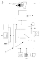
- an alarm system in the essentially from a control center 1, which is connected via a bus system 2 to at least one Identification or focusing device 3, at least one display device 4 and at least one alarm transmitter 5 and at least one detector 6 in connection stands.
- Monitoring device 7 there is at least one Monitoring device 7 available.
- the monitoring device 7 receives the messages intended for the two alarm devices 5 and checked them regarding the sending source. If the check finds that the Messages come from an unauthorized or unknown source by a corresponding one, which is output by the monitoring device 7 Command automatically reset the alarm 5 in the before Receiving message lying status. Is the monitoring device 7 how 2, in particular, is assigned directly to the two alarm devices 5, Alternatively, the forwarding of one of an unauthorized or unknown source message to the two alarm 5 completely be suppressed.
- the monitoring device 7 is in the Central 1 integrated. Since the control center 1 via the bus system 2 also with all others Components of the alarm system are connected and all functions influencing messages can be distributed via the bus system 2 Messages that are not sent from the control center 1 to the alarm device 5 come only from an unauthorized source. Will such a message are determined, the alarm 5 by a corresponding command Central 1 or the monitoring device 7 integrated therein back into the front status when the message was received. Specifically, that means at If sabotage is detected, the alarm devices 5 are either switched off again, or switched on again, depending on the status of the alarm device 5 have received the message.
- the identification or Focusing device 3 consists of a combination of a key actuating lock, a code entry device with keypad and a Smart card reader. Of course, the use of only one of these is Components, as well as using another combination of these Components and just as good to use one for simplicity here Identification or focusing device 3, not shown, possible.
- the display device 4 is a monitor to the control center 1, a light panel with LED displays and connected a transmission device. The transmission device is intended to deliver messages to a remote location from where all further measures can be initiated. In this case too of course the use of other components or another Combination of these components as a display device 4 is possible.
- Bus system 2 with alarm center 5 are connected trained as a flash light on the one hand and a siren on the other.
- the two An alarm 8 which receives the messages, is connected upstream of alarm devices 5 processed and the two alarm devices 5 controlled.
- the control center 1 is the detector 6 via the bus system 2 with a motion detector, several light barriers and several glass breakage detectors in connection. In this case too of course the use of other components or another A combination of these components as detector 6 is possible.
- the monitoring device 7 Sabotage message issued in the bus system 2 and via the display device 4 is displayed.
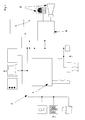
- the monitoring device 7 is direct assigned to the two alarm devices 5 and the associated actuators 8. So that is Monitoring device 7 is unable to forward messages authorized or unknown sources to the two alarm devices 5 entirely suppress. If a message from an unauthorized or unknown source is then also sent to the bus system 2 at the same time Central 1 passed on a sabotage message, so that a sabotage case is so quick is recognized as possible. The sabotage message is displayed via the Display device 4. All other components of the alarm system or their Connections to headquarters 1 have already been dealt with above and will be therefore not described here again.
- the monitoring device 7 is on the bus system 2 can be connected to a separate device.
- the Monitoring device 7 checks all those routed via bus system 2 News.
- the monitoring device 7 does not issue a message from one authorized or unknown source, is sent to everyone via the bus system connected components sends a sabotage message so that the Sabotage case is recognized as soon as possible.
- the two Alert 5 via the central 1 back in their before receiving the message status reset.
- the sabotage message is displayed in in any case via the display device 4. All other components of the Alarm system or its connections to the control center 1 are already above dealt with and are therefore not described again in detail here.
Landscapes
- Physics & Mathematics (AREA)
- General Physics & Mathematics (AREA)
- Business, Economics & Management (AREA)
- Emergency Management (AREA)
- Engineering & Computer Science (AREA)
- Computer Security & Cryptography (AREA)
- Alarm Systems (AREA)
Applications Claiming Priority (2)
| Application Number | Priority Date | Filing Date | Title |
|---|---|---|---|
| DE10322846 | 2003-05-19 | ||
| DE2003122846 DE10322846B3 (de) | 2003-05-19 | 2003-05-19 | Alarmanlage |
Publications (2)
| Publication Number | Publication Date |
|---|---|
| EP1480179A2 true EP1480179A2 (fr) | 2004-11-24 |
| EP1480179A3 EP1480179A3 (fr) | 2009-12-09 |
Family
ID=32946468
Family Applications (1)
| Application Number | Title | Priority Date | Filing Date |
|---|---|---|---|
| EP04008660A Ceased EP1480179A3 (fr) | 2003-05-19 | 2004-04-10 | Système d'alarme |
Country Status (2)
| Country | Link |
|---|---|
| EP (1) | EP1480179A3 (fr) |
| DE (1) | DE10322846B3 (fr) |
Family Cites Families (5)
| Publication number | Priority date | Publication date | Assignee | Title |
|---|---|---|---|---|
| US5293576A (en) * | 1991-11-21 | 1994-03-08 | Motorola, Inc. | Command authentication process |
| WO1997029465A1 (fr) * | 1996-02-08 | 1997-08-14 | Philips Electronics N.V. | Initialisation d'un systeme de securite sans fil |
| DE19940522A1 (de) * | 1999-08-26 | 2001-03-08 | Peter Skowronek | Außenüberwachungssystem |
| DE19944843B4 (de) * | 1999-09-18 | 2005-10-13 | Pax Gmbh I.K. | Alarmsystem |
| DE20021902U1 (de) * | 2000-12-23 | 2001-06-07 | Gretsch-Unitas GmbH Baubeschläge, 71254 Ditzingen | Gebäudemanagement-System |
-
2003
- 2003-05-19 DE DE2003122846 patent/DE10322846B3/de not_active Expired - Fee Related
-
2004
- 2004-04-10 EP EP04008660A patent/EP1480179A3/fr not_active Ceased
Also Published As
| Publication number | Publication date |
|---|---|
| DE10322846B3 (de) | 2004-10-07 |
| EP1480179A3 (fr) | 2009-12-09 |
Similar Documents
| Publication | Publication Date | Title |
|---|---|---|
| EP0484880A2 (fr) | Système radio d'alarme | |
| DE19506385C2 (de) | Drahtlose Gefahren-Meldeanlage und Meldeverfahren | |
| EP0248298B1 (fr) | Dispositif détecteur de danger | |
| DE102011008654B4 (de) | Beschlagsintegrierte Überwachungseinrichtung | |
| EP0376951A1 (fr) | Poste de radio pour vehicules automobiles avec dispositif anti-vol | |
| DE102014008808A1 (de) | Verfahren zur Absicherung der Übertragung von sicherheitsrelevanten Kamerabildern | |
| EP1480179A2 (fr) | Système d'alarme | |
| EP1351206B1 (fr) | Indicateur de passage de secours | |
| DE102006022525B4 (de) | Zeitverzögerter automatischer Notruf mit Deaktivierungsmöglichkeit | |
| EP0014714A1 (fr) | Dispositif d'alarme partiellement amovible avec protection contre le non-fonctionnement, la panne, le sabotage et la fausse alarme | |
| DE102004042999A1 (de) | Vorrichtung und Verfahren zum Prüfen einer Zugangsberechtigung zu einem geschützten Bereich | |
| DE2747388A1 (de) | Elektronisches kontrollsystem | |
| DE2923732C2 (de) | Anordnung zur Alarmgabe bei unbefugtem Eindringen in einen geschützten Bereich | |
| EP3185228A1 (fr) | Systeme et procede de surveillance d'installations de detection d'incendie | |
| DE4310690C2 (de) | Einrichtung zum Sichern von Kraftfahrzeugen gegen Einbruch und Diebstahl | |
| EP1444659A2 (fr) | Systeme de securite | |
| DE4423171A1 (de) | Vorrichtung zum Scharfschalten und zum zwangsläufigen Unscharfschalten einer Alarmanlage | |
| EP1480060B1 (fr) | Capteur optique | |
| DE19541742C1 (de) | Diebstahlwarneinrichtung | |
| EP1160751A1 (fr) | Détecteur de mouvement | |
| EP2064685B1 (fr) | Procédé et équipement pour l'identification d'un avertisseur de danger | |
| DE102017209937B4 (de) | System und Verfahren zum gewaltfreien Öffnen einer Tür durch die Feuerwehr | |
| DE2452864B2 (de) | Objektueberwachungsanlage | |
| DE102009022043B4 (de) | Drahtloses Kommunikationsverfahren zwischen mobiler Funkeinheit und einer Mehrzahl von Funkmodulen | |
| DE102004048585A1 (de) | Einbruchmeldeanlage |
Legal Events
| Date | Code | Title | Description |
|---|---|---|---|
| PUAI | Public reference made under article 153(3) epc to a published international application that has entered the european phase |
Free format text: ORIGINAL CODE: 0009012 |
|
| AK | Designated contracting states |
Kind code of ref document: A2 Designated state(s): AT BE BG CH CY CZ DE DK EE ES FI FR GB GR HU IE IT LI LU MC NL PL PT RO SE SI SK TR |
|
| AX | Request for extension of the european patent |
Extension state: AL HR LT LV MK |
|
| PUAL | Search report despatched |
Free format text: ORIGINAL CODE: 0009013 |
|
| AK | Designated contracting states |
Kind code of ref document: A3 Designated state(s): AT BE BG CH CY CZ DE DK EE ES FI FR GB GR HU IE IT LI LU MC NL PL PT RO SE SI SK TR |
|
| AX | Request for extension of the european patent |
Extension state: AL HR LT LV MK |
|
| RIC1 | Information provided on ipc code assigned before grant |
Ipc: G06F 13/36 20060101ALI20091030BHEP Ipc: G08B 13/22 20060101ALI20091030BHEP Ipc: G08B 25/14 20060101AFI20040830BHEP |
|
| 17P | Request for examination filed |
Effective date: 20100201 |
|
| AKX | Designation fees paid |
Designated state(s): AT BE BG CH CY CZ DE DK EE ES FI FR GB GR HU IE IT LI LU MC NL PL PT RO SE SI SK TR |
|
| RAP1 | Party data changed (applicant data changed or rights of an application transferred) |
Owner name: INSTA ELEKTRO GMBH |
|
| RAP1 | Party data changed (applicant data changed or rights of an application transferred) |
Owner name: INSTA ELEKTRO GMBH |
|
| 17Q | First examination report despatched |
Effective date: 20110310 |
|
| STAA | Information on the status of an ep patent application or granted ep patent |
Free format text: STATUS: THE APPLICATION HAS BEEN REFUSED |
|
| 18R | Application refused |
Effective date: 20110618 |