EP1480180A1 - Procédé et dispositif de commande à distance d'un dispositif médical - Google Patents
Procédé et dispositif de commande à distance d'un dispositif médical Download PDFInfo
- Publication number
- EP1480180A1 EP1480180A1 EP03011456A EP03011456A EP1480180A1 EP 1480180 A1 EP1480180 A1 EP 1480180A1 EP 03011456 A EP03011456 A EP 03011456A EP 03011456 A EP03011456 A EP 03011456A EP 1480180 A1 EP1480180 A1 EP 1480180A1
- Authority
- EP
- European Patent Office
- Prior art keywords
- infrared
- operating unit
- radio
- operated
- transmitter
- Prior art date
- Legal status (The legal status is an assumption and is not a legal conclusion. Google has not performed a legal analysis and makes no representation as to the accuracy of the status listed.)
- Granted
Links
Images

Classifications
-
- G—PHYSICS
- G08—SIGNALLING
- G08C—TRANSMISSION SYSTEMS FOR MEASURED VALUES, CONTROL OR SIMILAR SIGNALS
- G08C25/00—Arrangements for preventing or correcting errors; Monitoring arrangements
- G08C25/02—Arrangements for preventing or correcting errors; Monitoring arrangements by signalling back receiving station to transmitting station
-
- G—PHYSICS
- G08—SIGNALLING
- G08C—TRANSMISSION SYSTEMS FOR MEASURED VALUES, CONTROL OR SIMILAR SIGNALS
- G08C17/00—Arrangements for transmitting signals characterised by the use of a wireless electrical link
- G08C17/02—Arrangements for transmitting signals characterised by the use of a wireless electrical link using a radio link
-
- G—PHYSICS
- G08—SIGNALLING
- G08C—TRANSMISSION SYSTEMS FOR MEASURED VALUES, CONTROL OR SIMILAR SIGNALS
- G08C2201/00—Transmission systems of control signals via wireless link
- G08C2201/90—Additional features
- G08C2201/91—Remote control based on location and proximity
Definitions
- the invention relates to a method for the remote control of at least one medical device, taking the medical device to be operated by means of wirelessly controls a mobile control unit.
- the invention also relates to a device for carrying out the method.
- Medical devices such as operating tables, endoscopic devices, High-frequency surgical devices, but also imaging devices, are in increasingly controlled by means of mobile control units.
- the operating units are connected via a cable with the at least connected to a device to be operated.
- medical devices known operated remotely via an infrared or radio connection are also known operated remotely via an infrared or radio connection.
- the object of the present invention is a method and a device for remote control of a medical device of the aforementioned Further develop type such that ensured in a structurally simple manner can be that a remote control only in the presence of the control unit in the same room as the medical device to be operated possible is.
- This object is according to the invention in a method of the type mentioned solved by giving the device to be operated with a Radio receiver and an infrared transmitter coupled and the mobile control unit equipped with a radio transmitter and an infrared receiver, and that commands from the mobile control unit via a radio link transmits to the radio receiver and infrared signals from the infrared transmitter transmits to the mobile control unit via an infrared connection.
- the infrared signals can in this case Form control signal that is received by the operating unit.
- the operating unit comprises an infrared receiver.
- the limited ones Data transmission rates that can be achieved via the infrared connection, represent no limitation of the usability of the device, because over The infrared connection is mainly used to transmit presence control signals become.
- Control signals for operating the medical device are over the radio connection between the control unit and the radio receiver transmitted, which in turn coupled with the medical device to be operated is.
- the radio link can be made very stable here and allows the transmission of data at high transfer rates.
- the method according to the invention enables the operation of the operating unit with low power consumption, as the radio transmitter and the infrared receiver have only a low power consumption.
- the energy supply the mobile control unit can therefore easily by means of Batteries take place.
- control signals only then transferable by radio from the control unit to the radio receiver are if the control unit has previously received an infrared signal.
- the received infrared signal for example, to release the radio transmitter be used by the reception of the infrared signal in the position is set to transmit control signals by radio while it is being received the infrared signal is disabled.
- the transmission of a control command So sets in this preferred embodiment, the previous reception an infrared signal, wherein from the operating unit an infrared signal can only be received if between the operating unit and the infrared transmitter is a line of sight.
- control commands from a Signal processing unit are only processable after this before the receipt of infrared signals by the operating unit confirmed has been.
- one repeats infrared signals to the Operating unit transmits and preferably also monitors whether the control unit the reception of infrared signals confirmed. It can, for example be provided that periodically emits infrared signals, for example at intervals of about 5 seconds to about 30 seconds, preferably at a distance from 10 s.
- a control of at least one medical to be operated Device by means of the operating unit can then preferably only in the Trap occur that the operating unit receiving the periodically sent Infrared signals confirmed.
- the Confirmation of reception of infrared signals at periodic intervals has to be done. It has proved to be particularly favorable when a confirmation the reception of infrared signals has to take place after a predefinable Number of infrared signals was sent out.
- a constructive particularly simple embodiment is provided that of the operating unit every emitted infrared signal must be confirmed.
- the confirmation signal can be received from the operating unit in the form of a radio signal to be sent out.
- the operating unit with a Infrared transmitter equips and the confirmation signal in the form of an infrared signal sending out. The latter can then from a device to be operated assigned infrared receiver can be received.
- the radio receiver and the infrared transmitter are connected via a bus connection with each other, one to the bus connection one Central control unit and the at least one device to be operated connects.
- the bus connection can be in the form of electrical lines, for example or in the form of light guides.
- the use of a BUS connection allows a variety of medical devices to the radio receiver and to connect the infrared transmitter, with the help of which the devices be remotely operated by the mobile control unit.
- the infrared transmitter a double function. For one thing, it serves to send out a Control signal received from the mobile control unit and a presence control of the mobile control unit allows.
- at least one to be served medical device can be controlled via an infrared connection.
- Serving device can hereby preferably an operating table for use come. This usually has a height-adjustable support column as well an operating table top with at least one pivotally mounted Table top element.
- the operating table can be by means of Adjust a motor drive unit. The activation of the drive unit can via the infrared connection between the infrared transmitter and the operating table, the infrared transmitter in turn preferably via a BUS connection with the radio receiver and if necessary connected to other medical devices to be operated.
- Embodiment of the method according to the invention has the advantage that during commissioning of the mobile control unit, first between the Infrared transmitter and the operating unit data can be transmitted the subsequent establishment of the radio link between the control unit and enable the radio receiver. So, for example via the infrared connection, a synchronization of the radio transmitter of the operating unit done with the radio receiver. After synchronization Then the radio link between the control unit and the Radio receiver are constructed.
- a particularly user-friendly remote control can be achieved be that one of the operating unit via the radio link speech signals transmits to the radio receiver. This allows a voice-controlled Operation of the medical device.
- the radio signals can be used, for example, in the DECT (Digital Enhanced Cordless Telephone) method or in the Bluetooth method.
- DECT Digital Enhanced Cordless Telephone
- the invention also relates to a device for Remote control of at least one medical device, in particular for Implementation of the above method, wherein the device has a mobile control unit and from the operating unit via a wireless connection control signals to the device to be operated are.
- the object mentioned above is according to the invention solved in that the device to be operated with a radio receiver and an infrared transmitter and the control unit a radio transmitter and an infrared receiver, wherein control commands from the operating unit via a radio link to the radio receiver are transferable and wherein infrared signals from the infrared transmitter can be transmitted to the control unit via an infrared connection.
- a presence control of the operating unit such, that it is ensured that the operating unit in the same Room is like the medical device to use. So it can be up be ensured structurally simple manner that control commands the control unit only be executed or sent out if one Visual connection to the device to be operated.
- the operating unit is a Control command can only be transmitted by radio if the operating unit has been previously received an infrared signal. It is advantageous if the radio transmitter during operation of the operating unit is blocked until the operating unit received an infrared signal.
- the radio transmitter is coupled to the infrared receiver, wherein the radio transmitter due to the reception of an infrared signal by the Infrared receiver automatically releasable to transmit a control command is.
- a control command of the operating unit is to be operated by the Device executable only after receiving from the control unit an infrared signal was confirmed.
- the device is a data processing unit has, with the help of a control command of the operating unit only processable if the operating unit receiving the has confirmed an infrared signal of the data processing unit.
- the infrared signals are repeated - preferably periodically - can be sent out.
- the infrared transmitter at intervals of about 5 to 30 seconds, preferably at intervals from 10 s, an infrared control signal is send out.
- the acknowledgment signal confirming receipt of an infrared signal Operating unit is preferably emit by radio.
- the operating unit has an infrared transmitter comprises and the confirmation signal in the form of an infrared signal ausendbar is.
- the control unit has an infrared transmitter comprises and the confirmation signal in the form of an infrared signal ausendbar is.
- the device according to the invention are several devices to be operated with the radio receiver and coupled to the infrared transmitter and by means of the control unit wirelessly controllable.
- a central control unit and at least one to operating medical device are connected to each other via a bus connection, wherein to the bus connection a central control unit and at least one to operating medical device are connected.
- This can be both a wireless as well as a wired BUS connection is used come, in particular a bus connection by means of electrical cables or by means of a light guide.
- the central control unit can be arranged as stationary Be configured control panel, which is associated with a monitor, preferably a liquid crystal monitor. Alternatively, the central control unit have a touch-sensitive screen (touch-screen).
- a variety of medical devices can be connected to the bus connection which are optionally available from the central control unit and from the mobile operating unit are operable.
- the stationary infrared transmitter has one Design a dual function, on the one hand, a presence control the operating unit allows, with the infrared transmitter to the control unit infrared signals are transmitted, and on the other allows the infrared transmitter in such a configuration a remotely controlled operation of at least one medical device, for example an operating table.
- the device according to the invention are from the infrared transmitter via the infrared connection to the control unit Data transferable for establishing a radio connection between the operating unit and the radio receiver.
- Such a construction allows it in particular, via the infrared connection data for the synchronization of Transmit radio transmitter of the control unit with the fixed radio receiver.
- in the transmission of the radio signals in the Bluetooth method is such a configuration of the device according to the invention advantageous.
- a particularly simple operation of the at least one medical device can be done by the radio receiver, a voice recognition module is assigned, because this allows it from the operating unit To transmit voice signals for remote control of the medical device.
- voice recognition modules are known in the art.
- the mobile operating unit has a microphone.
- the operating unit may, for example, in the manner of a so-called Headsets be designed.
- the operating unit via a bidirectional Radio connection with the device to be operated is connectable. This allows feedback, for example, of status data of the user to be served Device via radio signal to the operating unit.
- radio connection between the operating unit and the device to be operated as a wireless network connection is configured.
- FIG. 1 schematically shows a reference numeral 10 as a whole Device for remote control of a medical device 12 shown.
- a medical device 12 can be, for example, an operating table with a height-adjustable Act support column and a pivoting table top.
- the medical device 12 to be operated is equipped with a stationary radio module 14 coupled and with a stationary infrared module 16.
- the coupling takes place in the embodiment shown in Figure 1 via connecting lines 15 or 17, but it could also be a wireless connection to Use or connect using fiber optics. It can also be provided be that the medical device 12 to a bus connection between the radio module 14 and the infrared module 16 is connected.
- the radio module 14 includes a fixed radio receiver 18. In addition can it, this is shown in dashed lines in Figure 1, a stationary radio transmitter 19 have.
- the infrared module 16 has a stationary infrared transmitter 21, in addition
- the infrared module 16 may have an infrared receiver shown in dashed lines in FIG include.
- the remote control device 10 shown in Figure 1 also includes a mobile control unit 25 with a mobile radio module 27 and a mobile Infrared module 29.
- the radio module 27 has a mobile radio transmitter 31 and, in addition, this is shown by dashed lines in FIG. 1, a mobile one Radio receiver 32 include.
- the infrared module 29 of the mobile control unit 25 has a mobile Infrared receiver 34 and can additionally dashed with a in Figure 1 shown mobile infrared transmitter 35 may be equipped.
- control commands can be received from the mobile radio transmitter 31 via a radio link 37 are transmitted to the fixed radio receiver 18, the via the connecting line 15 with the medical device to be operated 12 is connected.
- the reception of the infrared signals emitted by the stationary infrared transmitter can the mobile control unit 25 either via the radio link 37 to confirm. Alternatively it can be provided that the reception of the infrared signals by emitting an infrared confirmation signal by means of the mobile infrared transmitter 35 takes place.
- the combined use of the radio link 37 and the infrared connection 39 thus makes it possible that control signals with high data transmission rate of the mobile control unit 25 to the medical device to be operated 12 can be transmitted, but with the use of the infrared connection 39 is ensured that between the operating unit 25 and the medical device to be operated 12 is a line of sight.
- the operating unit 25 may be configured such that control commands via the radio link 37 can only be transmitted if previously an infrared signal was received.
- the establishment of the radio link 37 is done by means of data from the fixed Infrared transmitter 21 to the mobile infrared receiver 34 of the control unit 25 have been transferred.
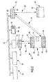
- FIG. 2 schematically shows a remote control device 50 according to the invention shown with a mobile control unit 52 for wireless control several medical devices 54, 56 and 58.
- the medical device 54 For example, it may be an operating table while the Devices 56 and 58, for example, as a high-frequency surgical device or endoscopic Device can be formed.
- the operation unit 25 also has the operating unit 52 a radio module 60 with a radio transmitter 61, wherein in addition, a dashed line in Figure 2 shown radio receiver 62 is provided can be.
- the operation unit 52 includes an infrared module 64 with an infrared receiver 65, wherein additionally a dashed line in Figure 2 illustrated infrared transmitter 66 can be used.
- the operating unit 52 is connected via a radio link 68 with a stationary Radio module 70 in connection, the stationary radio receiver 71st includes and in addition a dashed line in Figure 2 shown radio transmitter 72nd can have.
- the operation unit 52 differs from the above with reference to the figure 1 explained operating unit 25 in that they additionally has a microphone 74 so that a user input voice signals can, via the radio link 68 to the stationary radio module 70th be transmitted.
- the radio module 70 is connected to a voice recognition module 76 in electrical connection, which in turn to a bus system 78th connected to the turn a stationary central control unit 80, a stationary infrared module 82 as well as the medical devices to be operated 56 and 58 are connected.
- the central control unit 80 has a monitor 84 and a keyboard 86 through which a user can enter control commands.
- On the monitor 84 can the state of devices 54, 56 and 58 connected to the BUS system and the state of the operation unit 53 are displayed.
- the central control unit 80 also has a touch-sensitive screen (touch-screen), both the Status display as well as the input of control commands is used.
- the stationary infrared module 82 has, in accordance with the above Referring to Figure 1 illustrated infrared module 16 a fixed Infrared transmitter 88 and may additionally shown in dashed lines in Figure 2 Infrared receiver 89 include.
- Infrared receiver 89 By means of the stationary infrared transmitter 88 and optionally supplemented by the stationary infrared receiver 89th can between the fixed infrared module 82 and the mobile control unit 52 an optionally bidirectionally configured infrared connection 91 are formed, via the infrared signals from the stationary infrared transmitter 88 can be transmitted to the mobile control unit 52.
- These infrared signals serve primarily the presence control of the mobile control unit 52 such that it is ensured that the operating unit located in the room in which also the medical Devices 54, 56 and 58 are arranged.
- the medical device 54 via another infrared connection 93 are controlled using the fixed infrared transmitter 88, the again via the BUS system 78 with both the central control unit 80 as well as with the mobile control unit 82 is connected.
- the medical device 54 has an infrared receiver 95.
- Infrared transmitter 88 periodically spaced from typically 10 s infrared signals sent out, which are received by the mobile operating unit 52, which then emits a confirmation signal, preferably by radio, whose input is monitored by the central control unit 80.
- a confirmation signal preferably by radio
- control commands from the radio transmitter 61 can only be emitted if the infrared receiver 65 an infrared signal has received.
Landscapes
- Physics & Mathematics (AREA)
- General Physics & Mathematics (AREA)
- Engineering & Computer Science (AREA)
- Computer Networks & Wireless Communication (AREA)
- Endoscopes (AREA)
- Selective Calling Equipment (AREA)
- Measuring And Recording Apparatus For Diagnosis (AREA)
- Electrotherapy Devices (AREA)
- External Artificial Organs (AREA)
Priority Applications (3)
| Application Number | Priority Date | Filing Date | Title |
|---|---|---|---|
| DE50303031T DE50303031D1 (de) | 2003-05-20 | 2003-05-20 | Verfahren und Vorrichtung zur Fernsteuerung eines medizinischen Gerätes |
| EP03011456A EP1480180B1 (fr) | 2003-05-20 | 2003-05-20 | Procédé et dispositif de commande à distance d'un dispositif médical |
| AT03011456T ATE323928T1 (de) | 2003-05-20 | 2003-05-20 | Verfahren und vorrichtung zur fernsteuerung eines medizinischen gerätes |
Applications Claiming Priority (1)
| Application Number | Priority Date | Filing Date | Title |
|---|---|---|---|
| EP03011456A EP1480180B1 (fr) | 2003-05-20 | 2003-05-20 | Procédé et dispositif de commande à distance d'un dispositif médical |
Publications (2)
| Publication Number | Publication Date |
|---|---|
| EP1480180A1 true EP1480180A1 (fr) | 2004-11-24 |
| EP1480180B1 EP1480180B1 (fr) | 2006-04-19 |
Family
ID=33040971
Family Applications (1)
| Application Number | Title | Priority Date | Filing Date |
|---|---|---|---|
| EP03011456A Expired - Lifetime EP1480180B1 (fr) | 2003-05-20 | 2003-05-20 | Procédé et dispositif de commande à distance d'un dispositif médical |
Country Status (3)
| Country | Link |
|---|---|
| EP (1) | EP1480180B1 (fr) |
| AT (1) | ATE323928T1 (fr) |
| DE (1) | DE50303031D1 (fr) |
Cited By (4)
| Publication number | Priority date | Publication date | Assignee | Title |
|---|---|---|---|---|
| WO2007009881A3 (fr) * | 2005-07-20 | 2007-04-05 | Siemens Ag | Procede et dispositif pour utiliser sans cable un appareil notamment medical |
| FR2963148A1 (fr) * | 2010-07-20 | 2012-01-27 | Maquet S A | Systeme de gestion d'equipement d'un bloc operatoire et utilisation correspondante |
| RU2534371C1 (ru) * | 2013-07-02 | 2014-11-27 | Анатолий Аркадьевич Короткий | Способ дистанционного контроля за опасными производственными объектами на базе информационно-технологических систем с использованием средств радиочастотной идентификации и комплекс устройств для его реализации |
| WO2017162576A1 (fr) * | 2016-03-21 | 2017-09-28 | Fresenius Medical Care Deutschland Gmbh | Commande à distance des messages d'un appareil de dialyse |
Families Citing this family (1)
| Publication number | Priority date | Publication date | Assignee | Title |
|---|---|---|---|---|
| JP4539695B2 (ja) * | 2007-09-04 | 2010-09-08 | ソニー株式会社 | リモートコントロールシステム、電子機器および制御方法 |
Citations (7)
| Publication number | Priority date | Publication date | Assignee | Title |
|---|---|---|---|---|
| US4211998A (en) * | 1977-08-25 | 1980-07-08 | Stierlen-Maquet Aktiengesellschaft | Method of and remote control apparatus for remotely controlling a medical appliance |
| JPS5733847A (en) * | 1980-08-08 | 1982-02-24 | Nec Corp | Remote controller of household appliance |
| EP0514244A1 (fr) * | 1991-05-07 | 1992-11-19 | Jay Electronique | Installation pour la télécommande par liaison hertzienne d'un engin mobile motorisé |
| DE4300600A1 (de) * | 1993-01-13 | 1994-07-14 | Hella Kg Hueck & Co | Fernbedienbare Sicherungseinrichtung für Kraftfahrzeuge |
| US6188325B1 (en) * | 1988-05-04 | 2001-02-13 | Peter Samuel Vogel | Long distance remote control |
| DE19959877A1 (de) * | 1999-12-13 | 2001-07-05 | Sew Eurodrive Gmbh & Co | System zur Fernbedienung |
| US20020152008A1 (en) * | 1999-03-25 | 2002-10-17 | Canac Inc. | Method and apparatus for assigning addresses to components in a control system |
-
2003
- 2003-05-20 AT AT03011456T patent/ATE323928T1/de not_active IP Right Cessation
- 2003-05-20 EP EP03011456A patent/EP1480180B1/fr not_active Expired - Lifetime
- 2003-05-20 DE DE50303031T patent/DE50303031D1/de not_active Expired - Lifetime
Patent Citations (7)
| Publication number | Priority date | Publication date | Assignee | Title |
|---|---|---|---|---|
| US4211998A (en) * | 1977-08-25 | 1980-07-08 | Stierlen-Maquet Aktiengesellschaft | Method of and remote control apparatus for remotely controlling a medical appliance |
| JPS5733847A (en) * | 1980-08-08 | 1982-02-24 | Nec Corp | Remote controller of household appliance |
| US6188325B1 (en) * | 1988-05-04 | 2001-02-13 | Peter Samuel Vogel | Long distance remote control |
| EP0514244A1 (fr) * | 1991-05-07 | 1992-11-19 | Jay Electronique | Installation pour la télécommande par liaison hertzienne d'un engin mobile motorisé |
| DE4300600A1 (de) * | 1993-01-13 | 1994-07-14 | Hella Kg Hueck & Co | Fernbedienbare Sicherungseinrichtung für Kraftfahrzeuge |
| US20020152008A1 (en) * | 1999-03-25 | 2002-10-17 | Canac Inc. | Method and apparatus for assigning addresses to components in a control system |
| DE19959877A1 (de) * | 1999-12-13 | 2001-07-05 | Sew Eurodrive Gmbh & Co | System zur Fernbedienung |
Non-Patent Citations (1)
| Title |
|---|
| PATENT ABSTRACTS OF JAPAN vol. 006, no. 103 (E - 112) 12 June 1982 (1982-06-12) * |
Cited By (8)
| Publication number | Priority date | Publication date | Assignee | Title |
|---|---|---|---|---|
| WO2007009881A3 (fr) * | 2005-07-20 | 2007-04-05 | Siemens Ag | Procede et dispositif pour utiliser sans cable un appareil notamment medical |
| US8405490B2 (en) | 2005-07-20 | 2013-03-26 | Siemens Aktiengesellschaft | Wireless transmission for a medical device |
| FR2963148A1 (fr) * | 2010-07-20 | 2012-01-27 | Maquet S A | Systeme de gestion d'equipement d'un bloc operatoire et utilisation correspondante |
| WO2012017163A3 (fr) * | 2010-07-20 | 2012-04-12 | Maquet Sas | Système de gestion d'équipement d'un bloc opératoire et utilisation correspondante |
| RU2534371C1 (ru) * | 2013-07-02 | 2014-11-27 | Анатолий Аркадьевич Короткий | Способ дистанционного контроля за опасными производственными объектами на базе информационно-технологических систем с использованием средств радиочастотной идентификации и комплекс устройств для его реализации |
| WO2017162576A1 (fr) * | 2016-03-21 | 2017-09-28 | Fresenius Medical Care Deutschland Gmbh | Commande à distance des messages d'un appareil de dialyse |
| CN108885903A (zh) * | 2016-03-21 | 2018-11-23 | 费森尤斯医疗护理德国有限责任公司 | 用于透析设备的通知的远程控制 |
| US10896755B2 (en) | 2016-03-21 | 2021-01-19 | Fresenius Medical Care Deutschland Gmbh | Remote control of messages for a dialysis apparatus |
Also Published As
| Publication number | Publication date |
|---|---|
| EP1480180B1 (fr) | 2006-04-19 |
| ATE323928T1 (de) | 2006-05-15 |
| DE50303031D1 (de) | 2006-05-24 |
Similar Documents
| Publication | Publication Date | Title |
|---|---|---|
| EP0243811B1 (fr) | Dispositif de commande de rotatives d'impression | |
| EP1785965B1 (fr) | Méthode et dispositif pour la transmission bidirectionnelle de données par infrarouge entre une table de traitement et une télécommande | |
| EP3236709B1 (fr) | Procédé de commande d'un appareil de cuisson et appareil de cuisson | |
| EP1599991B1 (fr) | Agencement et module d'interface pour la connexion de divers radiotelephones mobiles a des composants de commande dans un vehicule a moteur | |
| DE10110776B4 (de) | Verfahren zur Zuordnung einer mobilen Bedien- und/oder Beobachtungseinrichtung zu einer Maschine sowie Bedien- und/oder Beobachtungseinrichtung hierfür | |
| EP1926069B1 (fr) | Télécommande radio | |
| EP2139803B1 (fr) | Procédé pour assurer la commande d'un dispositif de déplacement de charge et commande de dispositif de déplacement de charge | |
| EP3665117B1 (fr) | Système de télécommande et procédé pour l'operation du système de télécommande | |
| EP1251722A2 (fr) | Luminaire de bloc opératoire | |
| DE102009033427A1 (de) | Fahrzeug-Fernsteuerungsverfahren | |
| EP3625783A1 (fr) | Commutateur de commande, système de commande et procédé de commande d'une grue | |
| DE102017102597A1 (de) | Managementsystem für elektrische Vorrichtungen | |
| EP1497558A1 (fr) | Pompe a vide | |
| EP3003240B1 (fr) | Système de table d'opération | |
| EP1480180B1 (fr) | Procédé et dispositif de commande à distance d'un dispositif médical | |
| DE112021004506T5 (de) | Drahtlose Steuerung in einem Kabelzieh- und Zuführsystem, Einbeziehung durch Verweis | |
| DE102012220956A1 (de) | Erfassungssystem für ein automatisiertes Fahrzeug | |
| DE102007025796B4 (de) | Mobiler Leitstand einer Rotationsdruckmaschine | |
| DE10152444A1 (de) | Verfahren und Vorrichtung zum Ansteuern einer Fahrzeugzusatzeinrichtung | |
| EP1374199B1 (fr) | Systeme de commande a distance destine a des appareils de travaux automobiles | |
| DE102007014497A1 (de) | Roboter-Programmierhandgerät | |
| DE10116217A1 (de) | Bedienen von räumlich verteilt angeordneten technischen Vorrichtung | |
| DE10221179A1 (de) | Medizinisches Diagnose- und/oder Therapiegerät mit Verfahren zur fehlergeschützten Kommunikation mit diesem Gerät | |
| DE19617294A1 (de) | Sprachgeführte Ansteuervorrichtung zum Steuern beliebiger Endgeräte | |
| EP3454143B1 (fr) | Système d'automatisation de la gestion des bâtiments et procédé correspondant |
Legal Events
| Date | Code | Title | Description |
|---|---|---|---|
| PUAI | Public reference made under article 153(3) epc to a published international application that has entered the european phase |
Free format text: ORIGINAL CODE: 0009012 |
|
| AK | Designated contracting states |
Kind code of ref document: A1 Designated state(s): AT BE BG CH CY CZ DE DK EE ES FI FR GB GR HU IE IT LI LU MC NL PT RO SE SI SK TR |
|
| AX | Request for extension of the european patent |
Extension state: AL LT LV MK |
|
| 17P | Request for examination filed |
Effective date: 20050523 |
|
| AKX | Designation fees paid |
Designated state(s): AT BE BG CH CY CZ DE DK EE ES FI FR GB GR HU IE IT LI LU MC NL PT RO SE SI SK TR |
|
| GRAP | Despatch of communication of intention to grant a patent |
Free format text: ORIGINAL CODE: EPIDOSNIGR1 |
|
| GRAS | Grant fee paid |
Free format text: ORIGINAL CODE: EPIDOSNIGR3 |
|
| GRAA | (expected) grant |
Free format text: ORIGINAL CODE: 0009210 |
|
| AK | Designated contracting states |
Kind code of ref document: B1 Designated state(s): AT BE BG CH CY CZ DE DK EE ES FI FR GB GR HU IE IT LI LU MC NL PT RO SE SI SK TR |
|
| PG25 | Lapsed in a contracting state [announced via postgrant information from national office to epo] |
Ref country code: NL Free format text: LAPSE BECAUSE OF FAILURE TO SUBMIT A TRANSLATION OF THE DESCRIPTION OR TO PAY THE FEE WITHIN THE PRESCRIBED TIME-LIMIT Effective date: 20060419 Ref country code: SK Free format text: LAPSE BECAUSE OF FAILURE TO SUBMIT A TRANSLATION OF THE DESCRIPTION OR TO PAY THE FEE WITHIN THE PRESCRIBED TIME-LIMIT Effective date: 20060419 Ref country code: GB Free format text: LAPSE BECAUSE OF FAILURE TO SUBMIT A TRANSLATION OF THE DESCRIPTION OR TO PAY THE FEE WITHIN THE PRESCRIBED TIME-LIMIT Effective date: 20060419 Ref country code: FI Free format text: LAPSE BECAUSE OF FAILURE TO SUBMIT A TRANSLATION OF THE DESCRIPTION OR TO PAY THE FEE WITHIN THE PRESCRIBED TIME-LIMIT Effective date: 20060419 Ref country code: SI Free format text: LAPSE BECAUSE OF FAILURE TO SUBMIT A TRANSLATION OF THE DESCRIPTION OR TO PAY THE FEE WITHIN THE PRESCRIBED TIME-LIMIT Effective date: 20060419 Ref country code: RO Free format text: LAPSE BECAUSE OF FAILURE TO SUBMIT A TRANSLATION OF THE DESCRIPTION OR TO PAY THE FEE WITHIN THE PRESCRIBED TIME-LIMIT Effective date: 20060419 Ref country code: CZ Free format text: LAPSE BECAUSE OF FAILURE TO SUBMIT A TRANSLATION OF THE DESCRIPTION OR TO PAY THE FEE WITHIN THE PRESCRIBED TIME-LIMIT Effective date: 20060419 Ref country code: IE Free format text: LAPSE BECAUSE OF FAILURE TO SUBMIT A TRANSLATION OF THE DESCRIPTION OR TO PAY THE FEE WITHIN THE PRESCRIBED TIME-LIMIT Effective date: 20060419 |
|
| REG | Reference to a national code |
Ref country code: GB Ref legal event code: FG4D Free format text: NOT ENGLISH |
|
| PG25 | Lapsed in a contracting state [announced via postgrant information from national office to epo] |
Ref country code: AT Free format text: LAPSE BECAUSE OF NON-PAYMENT OF DUE FEES Effective date: 20060520 |
|
| REF | Corresponds to: |
Ref document number: 50303031 Country of ref document: DE Date of ref document: 20060524 Kind code of ref document: P |
|
| PG25 | Lapsed in a contracting state [announced via postgrant information from national office to epo] |
Ref country code: BE Free format text: LAPSE BECAUSE OF NON-PAYMENT OF DUE FEES Effective date: 20060531 Ref country code: MC Free format text: LAPSE BECAUSE OF NON-PAYMENT OF DUE FEES Effective date: 20060531 |
|
| REG | Reference to a national code |
Ref country code: IE Ref legal event code: FG4D Free format text: LANGUAGE OF EP DOCUMENT: GERMAN |
|
| PG25 | Lapsed in a contracting state [announced via postgrant information from national office to epo] |
Ref country code: DK Free format text: LAPSE BECAUSE OF FAILURE TO SUBMIT A TRANSLATION OF THE DESCRIPTION OR TO PAY THE FEE WITHIN THE PRESCRIBED TIME-LIMIT Effective date: 20060719 Ref country code: SE Free format text: LAPSE BECAUSE OF FAILURE TO SUBMIT A TRANSLATION OF THE DESCRIPTION OR TO PAY THE FEE WITHIN THE PRESCRIBED TIME-LIMIT Effective date: 20060719 |
|
| PG25 | Lapsed in a contracting state [announced via postgrant information from national office to epo] |
Ref country code: ES Free format text: LAPSE BECAUSE OF FAILURE TO SUBMIT A TRANSLATION OF THE DESCRIPTION OR TO PAY THE FEE WITHIN THE PRESCRIBED TIME-LIMIT Effective date: 20060730 |
|
| PG25 | Lapsed in a contracting state [announced via postgrant information from national office to epo] |
Ref country code: PT Free format text: LAPSE BECAUSE OF FAILURE TO SUBMIT A TRANSLATION OF THE DESCRIPTION OR TO PAY THE FEE WITHIN THE PRESCRIBED TIME-LIMIT Effective date: 20060919 |
|
| NLV1 | Nl: lapsed or annulled due to failure to fulfill the requirements of art. 29p and 29m of the patents act | ||
| GBV | Gb: ep patent (uk) treated as always having been void in accordance with gb section 77(7)/1977 [no translation filed] |
Effective date: 20060419 |
|
| REG | Reference to a national code |
Ref country code: IE Ref legal event code: FD4D |
|
| ET | Fr: translation filed | ||
| PLBE | No opposition filed within time limit |
Free format text: ORIGINAL CODE: 0009261 |
|
| STAA | Information on the status of an ep patent application or granted ep patent |
Free format text: STATUS: NO OPPOSITION FILED WITHIN TIME LIMIT |
|
| 26N | No opposition filed |
Effective date: 20070122 |
|
| BERE | Be: lapsed |
Owner name: TRUMPF MEDIZIN SYSTEME GMBH. Effective date: 20060531 |
|
| REG | Reference to a national code |
Ref country code: CH Ref legal event code: PL |
|
| PG25 | Lapsed in a contracting state [announced via postgrant information from national office to epo] |
Ref country code: CH Free format text: LAPSE BECAUSE OF NON-PAYMENT OF DUE FEES Effective date: 20070531 Ref country code: LI Free format text: LAPSE BECAUSE OF NON-PAYMENT OF DUE FEES Effective date: 20070531 |
|
| PG25 | Lapsed in a contracting state [announced via postgrant information from national office to epo] |
Ref country code: GR Free format text: LAPSE BECAUSE OF FAILURE TO SUBMIT A TRANSLATION OF THE DESCRIPTION OR TO PAY THE FEE WITHIN THE PRESCRIBED TIME-LIMIT Effective date: 20060720 |
|
| PG25 | Lapsed in a contracting state [announced via postgrant information from national office to epo] |
Ref country code: EE Free format text: LAPSE BECAUSE OF FAILURE TO SUBMIT A TRANSLATION OF THE DESCRIPTION OR TO PAY THE FEE WITHIN THE PRESCRIBED TIME-LIMIT Effective date: 20060419 Ref country code: BG Free format text: LAPSE BECAUSE OF FAILURE TO SUBMIT A TRANSLATION OF THE DESCRIPTION OR TO PAY THE FEE WITHIN THE PRESCRIBED TIME-LIMIT Effective date: 20060719 |
|
| PG25 | Lapsed in a contracting state [announced via postgrant information from national office to epo] |
Ref country code: TR Free format text: LAPSE BECAUSE OF FAILURE TO SUBMIT A TRANSLATION OF THE DESCRIPTION OR TO PAY THE FEE WITHIN THE PRESCRIBED TIME-LIMIT Effective date: 20060419 Ref country code: HU Free format text: LAPSE BECAUSE OF FAILURE TO SUBMIT A TRANSLATION OF THE DESCRIPTION OR TO PAY THE FEE WITHIN THE PRESCRIBED TIME-LIMIT Effective date: 20061020 Ref country code: LU Free format text: LAPSE BECAUSE OF NON-PAYMENT OF DUE FEES Effective date: 20060520 |
|
| PG25 | Lapsed in a contracting state [announced via postgrant information from national office to epo] |
Ref country code: CY Free format text: LAPSE BECAUSE OF FAILURE TO SUBMIT A TRANSLATION OF THE DESCRIPTION OR TO PAY THE FEE WITHIN THE PRESCRIBED TIME-LIMIT Effective date: 20060419 |
|
| REG | Reference to a national code |
Ref country code: DE Ref legal event code: R082 Ref document number: 50303031 Country of ref document: DE Representative=s name: HOEGER, STELLRECHT & PARTNER PATENTANWAELTE MB, DE |
|
| REG | Reference to a national code |
Ref country code: FR Ref legal event code: PLFP Year of fee payment: 14 |
|
| PGFP | Annual fee paid to national office [announced via postgrant information from national office to epo] |
Ref country code: DE Payment date: 20160518 Year of fee payment: 14 |
|
| PGFP | Annual fee paid to national office [announced via postgrant information from national office to epo] |
Ref country code: IT Payment date: 20160524 Year of fee payment: 14 Ref country code: FR Payment date: 20160412 Year of fee payment: 14 |
|
| REG | Reference to a national code |
Ref country code: DE Ref legal event code: R119 Ref document number: 50303031 Country of ref document: DE |
|
| REG | Reference to a national code |
Ref country code: FR Ref legal event code: ST Effective date: 20180131 |
|
| PG25 | Lapsed in a contracting state [announced via postgrant information from national office to epo] |
Ref country code: DE Free format text: LAPSE BECAUSE OF NON-PAYMENT OF DUE FEES Effective date: 20171201 |
|
| PG25 | Lapsed in a contracting state [announced via postgrant information from national office to epo] |
Ref country code: IT Free format text: LAPSE BECAUSE OF NON-PAYMENT OF DUE FEES Effective date: 20170520 Ref country code: FR Free format text: LAPSE BECAUSE OF NON-PAYMENT OF DUE FEES Effective date: 20170531 |