EP1480221A1 - Verpackung für einen scheibenförmigen Aufzeichnungsträger und Verfahren zum Konfektionieren einer solchen Verpackung - Google Patents
Verpackung für einen scheibenförmigen Aufzeichnungsträger und Verfahren zum Konfektionieren einer solchen Verpackung Download PDFInfo
- Publication number
- EP1480221A1 EP1480221A1 EP03090156A EP03090156A EP1480221A1 EP 1480221 A1 EP1480221 A1 EP 1480221A1 EP 03090156 A EP03090156 A EP 03090156A EP 03090156 A EP03090156 A EP 03090156A EP 1480221 A1 EP1480221 A1 EP 1480221A1
- Authority
- EP
- European Patent Office
- Prior art keywords
- molded body
- pin
- shaped
- packaging according
- packaging
- Prior art date
- Legal status (The legal status is an assumption and is not a legal conclusion. Google has not performed a legal analysis and makes no representation as to the accuracy of the status listed.)
- Granted
Links
- 238000003860 storage Methods 0.000 title claims description 19
- 238000004519 manufacturing process Methods 0.000 title description 5
- 238000004806 packaging method and process Methods 0.000 claims abstract description 51
- 238000000034 method Methods 0.000 claims abstract description 13
- 239000004033 plastic Substances 0.000 claims description 13
- 239000000853 adhesive Substances 0.000 claims description 8
- 230000001070 adhesive effect Effects 0.000 claims description 8
- 238000000465 moulding Methods 0.000 claims description 5
- -1 non-woven Substances 0.000 claims description 5
- 238000004026 adhesive bonding Methods 0.000 claims description 4
- 238000003780 insertion Methods 0.000 claims 2
- 230000037431 insertion Effects 0.000 claims 2
- 238000003825 pressing Methods 0.000 claims 2
- 230000000149 penetrating effect Effects 0.000 claims 1
- 239000000463 material Substances 0.000 abstract description 4
- 239000003292 glue Substances 0.000 abstract 1
- 238000002347 injection Methods 0.000 description 2
- 239000007924 injection Substances 0.000 description 2
- 239000002991 molded plastic Substances 0.000 description 2
- 210000001331 nose Anatomy 0.000 description 2
- 239000004743 Polypropylene Substances 0.000 description 1
- 238000005452 bending Methods 0.000 description 1
- 239000000969 carrier Substances 0.000 description 1
- 230000006735 deficit Effects 0.000 description 1
- 238000007373 indentation Methods 0.000 description 1
- 238000001746 injection moulding Methods 0.000 description 1
- 230000010354 integration Effects 0.000 description 1
- 230000007246 mechanism Effects 0.000 description 1
- 239000005022 packaging material Substances 0.000 description 1
- 238000012856 packing Methods 0.000 description 1
- 229920001155 polypropylene Polymers 0.000 description 1
- 239000000243 solution Substances 0.000 description 1
- 238000005507 spraying Methods 0.000 description 1
- 238000011144 upstream manufacturing Methods 0.000 description 1
Images


Classifications
-
- G—PHYSICS
- G11—INFORMATION STORAGE
- G11B—INFORMATION STORAGE BASED ON RELATIVE MOVEMENT BETWEEN RECORD CARRIER AND TRANSDUCER
- G11B33/00—Constructional parts, details or accessories not provided for in the other groups of this subclass
- G11B33/02—Cabinets; Cases; Stands; Disposition of apparatus therein or thereon
- G11B33/04—Cabinets; Cases; Stands; Disposition of apparatus therein or thereon modified to store record carriers
- G11B33/0405—Cabinets; Cases; Stands; Disposition of apparatus therein or thereon modified to store record carriers for storing discs
- G11B33/0411—Single disc boxes
- G11B33/0422—Single disc boxes for discs without cartridge
- G11B33/0427—Single disc boxes for discs without cartridge comprising centre hole locking means
Definitions
- the invention relates to a packaging for one disc-shaped recording media, for example DVD / CD storage media, with one holding the record carrier box-shaped molded body made of plastic and with one a cover layer and supine layer formed from a folded blank made of cardboard, cardboard, fleece, Plastic or the like. And which one on two adjacent outer edges open recording space has, in which the shaped body by a between the Cover layer and supine position in the corner area of the open edges fixedly positioned pin in a pin hole of the Shaped body is pivotally arranged, wherein the shaped body on its narrow side opposite the pin with a Bleed is provided, which diagonally to the tenon inwards is arranged progressively.
- the invention further relates to a method for Packing a packaging for a disc-shaped Record carriers, for example DVD storage media, at that of cardboard, cardboard, fleece, plastic or the like folded blank for one from a cover sheet and Supine formed wrapping manufactured box-shaped molded body made of plastic and the Shaped body between the inner cover layer and the Supine position in the corner area of the open edges fixed positioned pin in a pin hole of the molded body is pivotally glued.
- a packaging for a disc-shaped Record carriers for example DVD storage media
- a cover sheet and Supine formed wrapping manufactured box-shaped molded body made of plastic and the Shaped body between the inner cover layer and the Supine position in the corner area of the open edges fixed positioned pin in a pin hole of the molded body is pivotally glued.
- the Molding has opposite the recess and the holding means raised longitudinal and transverse walls that form an interior circumscribe. On its edge facing the bottom part of the A film hinge band is formed on the transverse walls Foldable towards the bottom and along the belt arranged evenly spaced retaining lugs is provided.
- the bottom part facing edge of the longitudinal wall facing the back part is a foldable away from the bottom part Film hinge tape formed in an angular shape.
- the vertical has protruding legs of the film hinge band two noses on the inside, which when folding the Film hinge band snapping in the direction of the longitudinal wall engage behind.
- the front cover is on the molding closed.
- the packaging is opened by loosening the Locking the leg of the film hinge from the Longitudinal wall.
- the lid is folded back and that Storage medium is removable.
- DE 38 20 239 A1 describes packaging for disc-shaped products, for example records, Disks, compact disks or the like are known.
- This packaging points parallel between two at a distance from each other arranged level and in the edge area with each other connected discs a disc-shaped product carrier on the one with the slices between one the product through completely covering the panes and one through the product the fully releasing position is pivotable.
- Similar solutions are disclosed in DE 298 00 899 U1, GB 2 276 609 A, US 5 425 451 A and WO 98 / 04478A1, in which the the CD-carrying slipcase shaped body can be pivoted with the Shell is connected.
- the object of the invention underlying, while maintaining a simple, reliable and user-friendly handling of the packaging To reduce the proportion of high quality plastic that Manufacturing cheaper and at the same time with inclusion to make a guarantee lock more secure.
- the packaging according to the invention essentially consists of an injection molded plastic body which can be given away against a rear and front stop around a pin located near the corner between the narrow and long sides. It is particularly advantageous that the rear stop is formed by a stop part which is connected to the molded body via a predetermined breaking line.
- the integration of the predetermined breaking line into the interior of the packaging creates a guarantee closure, the production of which is possible inexpensively in the upstream injection process.
- the predetermined breaking line can be achieved very simply by slightly bending the stop part at the corner opposite the pin.
- Both the pin and the connecting part are designed as hollow parts and have adhesive surfaces with a surface structure that enables the adhesive to adhere preferentially.
- the pin is integrally molded onto the molded body, so that the pin can be pressed into the pin hole in the subsequent assembly.
- the rear stop part and the pin are firmly glued between an inner cover layer and a back layer during the adhesive process.
- the rear stop prevents the adhesive connection holding the pin from being overstressed.
- the molded part produced by injection molding can also be made from recycled plastic, since there are no hinge and snap-in connections. It is particularly advantageous that the covering of the molded part consists of cardboard material, which can be produced and printed inexpensively using devices suitable for packaging materials.
- the storage medium By swiveling the molded body out of the receiving space formed by the casing, the storage medium can be easily removed from the molded body without additional manipulations such as loosening the cover or other snap locks being necessary. Inserting the storage medium in the recording room is just as easy. The molded body is only pivoted into the receiving space and is therefore securely accommodated.
- the packaging according to the invention is also suitable for accommodating storage media recorded on both sides. All that is required is to accommodate the receiving space on the top and bottom of the molded body accordingly.
- the packaging according to the invention has the advantage that a plurality of receiving spaces, for example a first space on the cover and a second space on the base part, can be provided for pivotally accommodating molded parts. All top and bottom surfaces of the blank can be printed, so that there are various design and design options.
- the packaging according to the invention for a DVD recording medium essentially consists of a wrapping 1 made of cardboard and a molded body 3 made of injection-molded plastic which is pivotably fastened in the wrapping about a pin 2 .
- the covering 1 with cover layer 4 and back layer 5 is known to be produced from a blank comprising several surfaces, the detailed description of which can therefore be dispensed with.
- the cover layer 4 and the back layer 5 have cutouts 6 and 7, which correspond to one another, on their front longitudinal sides L v for gripping the molded body 3 .
- the upper narrow side S o of the molded body 3 has a cut 8 which runs inwards in the direction of the diagonally opposite corner from the mortise 9 .
- the pin hole 9 is introduced near the lower narrow side S u and the front longitudinal side L v of the molded body 3 in the lower front corner E v .
- the pin 2 is temporarily held by a material connection, which will be described in detail later.
- a rear stop surface 10 is formed between the rear long side L H and the lower horizontal narrow side S u of the molded body 3 , which includes an angle ⁇ of 45 ° with respect to the rear long side L H and the lower narrow side S u .
- the result is a pentagonal shaped body 3 , the long and narrow sides L and S of which all have different lengths.
- the molded body 3 has on its upper side O s and / or lower side U S a receptacle 11 for storing a record carrier, not shown.
- the receptacle 11 has a circular edge 12 which is reinforced by a web 13 shaped like a ring gear on the outside toward the edge 12 .
- receptacle 11 Centrally arranged in the receptacle 11 are star-shaped product holders 14 with holding projections 15 for holding the record carrier.
- Pointed elevations 17 are formed on the upper side O S or lower side U S of the shaped body 3 at four opposite locations within the receptacle 11 near the edge 12 , which ensure a punctiform support of the recording medium.
- the molded body 3 is bordered on the edge by a web 18 which rises vertically on the longitudinal and narrow sides. The height of this web 18 corresponds to the height of the receiving space 19 of the casing 1 .
- a gripping part 20 which extends into the cutouts 6 and 7 , for pivoting the molded body 3 out and in into the receiving space 19 of the casing 1 on the inside of the web 18 .
- This gripping part 20 can be formed over the entire surface or structured and have a height that corresponds to the outer height of the casing, so that it forms a front stop for the molded body 3 .
- the stop piece 21 is shaped as a polyhedral body 23 , which forms the rear lower corner E H of the shaped body 3 and whose height corresponds to the height of the web 18 .
- the body 23 consists of triangular, cup-shaped parts 24 which adjoin one another in a meandering manner, the bottom surfaces 25 of which are provided with a profile, for example small cams 26 .
- the long side of the body 23 opposite the lower rear corner E H forms a stop surface 27 , which corresponds in position, angular position and dimension of the stop surface 10 of the molded body 3.
- FIG. 3 shows a section through the predetermined breaking line 22 , which runs approximately centrally on the stop surfaces 27 of the stop piece 21 and the stop surface 10 of the molded body 3.
- the predetermined breaking line 22 has an X shape, the opening angle ⁇ of which is approximately 30 °.
- the bottom surfaces 25 of the stop piece 21 are glued to the inner cover layer 4 and the back layer 5 .
- the stop piece 27 thus forms the lower rear corner E H of the packaging. If this corner E H along the predetermined breaking line 22 , ie along the abutment surfaces 10 and 27, is subjected to a slight kink, the predetermined breaking line 22 breaks and separates the molded body 3 from the fixed abutment piece 21 .
- the pin hole 9 has an outer circular collar 28 , in which diametrically opposite recesses 29 are formed.
- the collar 28 is supported with the cutouts 29.1 and 29.2 on the circumferential web 18 of the molded body 3 , which in each case limit the front longitudinal side L v and the lower narrow side S u .
- the pin 2 is shaped as a circular-cylindrical hollow body 30 , which is divided into four equal-sized circular segment-like cups 32 by webs 31 arranged in the shape of a cross in the hollow body 30 .
- two bowls 32 have a common bottom surface 33 , the outer surface of which is provided with groove-shaped elevations 34 , the bottom surface 33 extending in a meandering manner, so that the bottom surfaces 33 of two wells 32 each form an upper and lower adhesive surface.
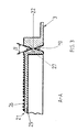
- 4 and 5 make it clear that the pin 2 is integrally connected to the pin hole 9 by a strip-like connection 35 after the spraying process.
- the pin 2 also has a collar 36 which is interrupted by recesses 37 .
- the collar 36 of the pin 2 has a diameter which is slightly smaller than the diameter of the collar 28 of the pin hole 9 .
- the recesses 29 of the pin hole 9 are integrally connected to the recesses 37 by the strips 35 , so that the pin 2 is fixed on the pin hole 9 ready to be pressed in before the assembly.
- the pin 2 is pressed into the pin hole 9 .
- the integral connection 35 between the pin 2 and the pin hole 9 and the pin 2 can be fixed with its respective bottom surfaces 33 to the inner cover layer 4 and the back layer 5 by gluing.
- the molded body 3 is thus pivotable about the pin 2 , provided that the predetermined breaking line 22 has been broken up by a corresponding buckling.
- the record carrier is inserted into the molded body 3 and the packaging is then made up.
- the user of the record carrier must then, as described, release the predetermined breaking line 22 by a slight kink along the predetermined breaking line.
- the packaging according to the invention thus enables precise, controlled access to the contents of the packaging.
Landscapes
- Packaging Of Annular Or Rod-Shaped Articles, Wearing Apparel, Cassettes, Or The Like (AREA)
- Packaging For Recording Disks (AREA)
- Making Paper Articles (AREA)
Abstract
Description
Der Aufwand steigt durch zusätzlich anzubringende Garantieverschlüsse an den Verpackungen.
Durch die Integration der Sollbruchlinie in das Innere der Verpackung entsteht ein Garantieverschluss, dessen Herstellung kostengünstig im vorgelagerten Spritzprozess möglich ist. Die Sollbruchlinie kann sehr einfach durch ein leichtes Knicken des Anschlagteiles an der dem Zapfen gegenüberliegenden Ecke erreicht werden.
Sowohl der Zapfen als auch das Anschlussteil ist als Hohlteil ausgebildet und besitzt Klebflächen mit einer Oberflächenstruktur, die ein bevorzugtes Haften des Klebstoffes ermöglicht.
Der Zapfen ist stoffschlüssig am Formkörper angespritzt, so dass der Zapfen in das Zapfenloch bei der nachfolgenden Konfektionierung eingedrückt werden kann.
Das hintere Anschlagteil und der Zapfen wird beim Klebeprozess zwischen einer inneren Abdecklage und einer Rückenlage fest eingeklebt. Der hintere Anschlag vermeidet, dass die den Zapfen haltende Klebverbindung überbeansprucht wird. Mit dem vorderen Anschlag, der sich gegen die innere Abdecklage und die Rückenlage abstützt, wird ein einfaches Herausschwenken des Formkörpers aus dem Aufnahmeraum zwischen innerer Abdecklage und Rückenteil ermöglicht.
Besonders vorteilhaft ist es, dass die Umhüllung des Formteiles aus Kartonmaterial besteht, das sich kostengünstig mit für Verpackungsmaterialien geeignete Vorrichtungen herstellen und bedrucken lässt.
Durch das Herausschwenken des Formkörpers aus dem von der Umhüllung gebildeten Aufnahmeraum ist eine einfache Entnahme des Speichermediums aus dem Formkörper möglich, ohne dass zusätzliche Handgriffe wie das Lösen des Deckels oder anderen Rastverschlüssen notwendig sind. Ebenso unkompliziert ist das Einlegen des Speichermediums in den Aufnahmeraum. Der Formkörper wird nur in den Aufnahmeraum eingeschwenkt und ist somit sicher untergebracht.
Die erfindungsgemäße Verpackung eignet sich auch dazu, doppelseitig bespielte Speicherträger aufzunehmen. Hierzu bedarf es nur den Aufnahmeraum an der Oberseite und Unterseite des Formkörpers entsprechend unterzubringen. Des weiteren hat die erfindungsgemäße Verpackung den Vorteil, dass mehrere Aufnahmeräume, beispielsweise ein erster Raum am Deckel und ein zweiter Raum am Bodenteil, zur schwenkbaren Aufnahme von Formteilen vorgesehen werden können.
Alle Deckel- und Bodenflächen des Zuschnitts lassen sich bedrucken, so dass vielfältige Design- und Gestaltungsmöglichkeiten vorhanden sind.
- Fig. 1
- eine perspektivische Ansicht der erfindungsgemäßen Verpackung mit einem teilweise herausgeschwenkten Formkörper,
- Fig. 2
- eine perspektivische Ansicht des Formkörpers mit angesetztem hinteren Anschlagstück und angespritztem Zapfen,
- Fig. 3
- einen Schnitt durch die Sollbruchlinie zwischen Formkörper und Anschlagstück entlang der Linie A-A in Fig. 2,
- Fig. 4
- einen Schnitt entlang der Linie B-B in Fig. 2,
- Fig. 5
- eine Einzelheit X in Fig. 4 und
- Fig. 6
- eine perspektivische Ansicht der erfindungsgemäßen Verpackung mit eingeschobenem Formkörper.
Die Umhüllung 1 mit Abdecklage 4 und Rückenlage 5 wird bekanntlich aus einem mehrere Flächen umfassenden Zuschnitt hergestellt, auf deren nähere Beschreibung deshalb verzichtet werden kann.
Die Abdecklage 4 und die Rückenlage 5 haben an ihren vorderen Längsseiten Lv jeweils zueinander korrespondierende Ausschnitte 6 und 7 zum Greifen des Formkörpers 3.
Das Zapfenloch 9 ist nahe der unteren Schmalseite Su und der vorderen Längsseite Lv des Formkörpers 3 in der vorderen unteren Ecke Ev eingebracht. Am Zapfenloch 9 wird der Zapfen 2 durch eine stoffschlüssige Verbindung temporär gehalten, die später im Einzelnen beschrieben wird.
Es entsteht dadurch ein fünfeckiger Formkörper 3, dessen Längs- und Schmalseiten L und S alle unterschiedliche Längen aufweisen. Der Formkörper 3 besitzt auf seiner Oberseite Os und/oder Unterseite US eine Aufnahme 11 für die Ablage eines nicht dargestellten Aufzeichnungsträgers. Die Aufnahme 11 hat einen kreisförmigen Rand 12, der durch einen außenseitig zum Rand 12 zahnkranzartig geformten Steg 13 verstärkt ist. Zentrisch in der Aufnahme 11 befinden sich sternförmig angeordnete Füllguthalter 14 mit Haltevorsprüngen 15 zum Halten des Aufzeichnungsträgers. Mittels zweier diagonal gegenüberliegender Durchgriffsöffnungen 16, die den Rand 12 und Steg 13 unterbrechen, ist es möglich, den Aufzeichnungsträger vom Füllguthalter 14 zu lösen, zu entnehmen oder wieder einzulegen.
Nahe des Randes 12 sind innerhalb der Aufnahme 11 an vier gegenüberliegenden Stellen punktförmige Erhebungen 17 an die Oberseite OS bzw. Unterseite US des Formkörpers 3 angeformt, die eine punktförmige Auflage des Aufzeichnungsträgers gewährleisten.
Der Formkörper 3 ist randseitig von einem an den Längs- und Schmalseiten senkrecht aufragenden Steg 18 umgrenzt. Die Höhe dieses Steges 18 entspricht der Höhe des Aufnahmeraumes 19 der Umhüllung 1.
Den Ausschnitten 6 und 7 in der inneren Abdecklage 4 und Rückenlage 5 zugeordnet ist ein sich in die Ausschnitte 6 und 7 erstreckendes Greifteil 20 zum Heraus- und Hineinschwenken des Formkörpers 3 in den Aufnahmeraum 19 der Umhüllung 1 innenseitig am Steg 18 angeformt. Dieses Greifteil 20 kann vollflächig oder strukturiert ausgebildet sein und eine Höhe haben, die der äußeren Höhe der Umhüllung entspricht, so dass es einen vorderen Anschlag für den Formkörper 3 bildet.
Bei der Konfektionierung der erfindungsgemäßen Verpackung werden die Bodenflächen 25 des Anschlagstücks 21 mit der inneren Abdecklage 4 und der Rückenlage 5 verklebt. Das Anschlagstück 27 bildet so die untere hintere Ecke EH der Verpackung. Wird diese Ecke EH entlang der Sollbruchlinie 22, d.h. entlang der Anschlagflächen 10 und 27 leicht auf Knick belastet, bricht die Sollbruchlinie 22 und trennt den Formkörper 3 vom festgelegten Anschlagstück 21 ab.
Der Zapfen 2 ist als ein kreiszylinderartiger Hohlkörper 30 geformt, der durch kreuzförmig im Hohlkörper 30 angeordnete Stege 31 in vier gleichgroße kreissegmentartige, gegeneinander abstützende Näpfe 32 eingeteilt sind. Jeweils zwei Näpfe 32 besitzen eine gemeinsame Bodenfläche 33, deren äußere Fläche mit nutenförmigen Erhebungen 34 versehen ist, wobei die Bodenfläche 33 mäanderförmig verläuft, so dass die Bodenflächen 33 jeweils zweier Näpfe 32 eine obere und untere Klebfläche bilden.
Fig. 4 und 5 macht deutlich, dass der Zapfen 2 nach dem Spritzvorgang mit dem Zapfenloch 9 durch eine streifenartige Verbindung 35 stoffschlüssig verbunden ist.
Der Zapfen 2 besitzt ebenfalls einen Bund 36, der durch Aussparungen 37 unterbrochen ist. Der Bund 36 des Zapfens 2 hat einen Durchmesser, der gegenüber dem Durchmesser des Bundes 28 des Zapfenloches 9 geringfügig geringer ist. Die Aussparungen 29 des Zapfenloches 9 sind mit den Aussparungen 37 durch die Streifen 35 stoffschlüssig verbunden, so dass der Zapfen 2 eindrückbereit am Zapfenloch 9 bereits vor der Konfektionierung festgelegt ist.
Sobald die Verpackung konfektioniert wird, d. h. der Formkörper 3 mit der Abdecklage 3 und der Rückenlage 4 verbunden wird, wird der Zapfen 2 in das Zapfenloch 9 eingedrückt. Durch das Eindrücken reißt die stoffschlüssige Verbindung 35 zwischen dem Zapfen 2 und dem Zapfenloch 9 und der Zapfen 2 kann mit seinen jeweiligen Bodenflächen 33 an der inneren Abdecklage 4 und der Rückenlage 5 durch Klebung fixiert werden. Der Formkörper 3 ist damit um den Zapfen 2 schwenkbar, sofern die Sollbruchlinie 22 durch entsprechende Knickung aufgebrochen wurde.
Soll die Sollbruchlinie 22 als Garantieverschluss eingesetzt werden, wird der Aufzeichnungsträger in den Formkörper 3 eingelegt und die Verpackung anschließend konfektioniert. Der Nutzer des Aufzeichnungsträgers muss dann, wie beschrieben, die Sollbruchlinie 22 durch eine leichte Knickung entlang der Sollbruchlinie lösen.
Die erfindungsgemäße Verpackung ermöglicht somit einen exakten kontrollierten Zugriff zum Inhalt der Verpackung.
- Umhüllung
- 1
- Zapfen
- 2
- Formkörper
- 3
- Innere Abdecklage
- 4
- Rückenlage
- 5
- Ausschnitte in Lv
- 6, 7
- Anschnitt
- 8
- Zapfenloch
- 9
- Hintere Anschlagfläche
- 10
- Aufnahme
- 11
- Kreisförmiger Rand von 11
- 12
- Zahnkranzartiger Steg von 12
- 13
- Füllguthalter
- 14
- Haltevorsprünge
- 15
- Durchgriffsöffnung
- 16
- Punktförmige Erhebungen
- 17
- Steg von 3
- 18
- Aufnahmeraum in 1
- 19
- Griffteil
- 20
- Anschlagstück
- 21
- Sollbruchlinie
- 22
- Polyedrischer Körper
- 23
- Napfförmige Teile
- 24
- Bodenfläche von 21
- 25
- Nocken an 25
- 26
- Anschlagfläche von 21
- 27
- Bund von 9
- 28
- Aussparungen von 28
- 29,29.1,29.2
- Hohlkörper von 2
- 30
- Stege von 30
- 31
- Näpfe von 30
- 32
- Bodenfläche von 32
- 33
- Nutenförmige Erhebungen
- 34
- Stoffschlüssige Streifen
- 35
- Bund von 2
- 36
- Aussparungen in 2
- 37
- Vordere untere Ecke
- Ev
- Hintere untere Ecke
- EH
- Längsseiten
- L
- Schmalseiten
- S
- Vordere Längsseite
- Lv
- Hintere Längsseite
- LH
- Obere Schmalseite
- So
- Untere Schmalseite
- SU
- Oberseite von 3
- OS
- Unterseite von 3
- US
- Winkel
- α
- Öffnungswinkel an 22
- β
Claims (20)
- Verpackung für einen scheibenförmigen Aufzeichnungsträger, beispielsweise DVD/CD-Speichermediun, mit einem den Aufzeichnungsträger haltenden kastenförmigen Formkörper aus Kunststoff und mit einer aus einer Abdecklage und Rückenlage gebildeten Umhüllung, die aus einem gefalteten Zuschnitt aus Karton, Pappe, Vlies, Kunststoff oder dgl. besteht und welche einen durch eine innere Abdecklage und einem Rückenteil umgrenzten, mindestens an zwei aneinandergrenzenden äußeren Rändern offenen Aufnahmeraum aufweist, in dem der Formkörper um einen zwischen der Abdecklage und Rückenlage im Eckbereich der offenen Ränder feststehend positionierten Zapfen in einem Zapfenloch des Formkörpers schwenkbar angeordnet ist, wobei der Formkörper an seiner dem Zapfen gegenüberliegenden Schmalseite mit einem Anschnitt versehen ist, der diagonal zum Zapfen nach innen verlaufend angeordnet ist, gekennzeichnet durch folgende Merkmale:a) dem Formkörper (3) ist ein durch Klebverbindung von der Abdecklage (4) und Rückenlage (5) im zum Zapfen (2) gegenüberliegenden Eckbereich (EH ) gehaltenes, inneres Anschlagstück (21) mit einer Anschlagfläche (27) zugeordnet, welches mit einer korrespondierenden Anschlagfläche (10) des Formkörpers (3) durch eine Sollbruchlinie (22) stoffschlüssig verbunden ist,b) der Formkörper (3) hat an seinem der Einschuböffnung zugeordneten Längsseiten ein Greifteil (20), das im eingeschobenen Zustand in entsprechende Ausschnitte (6;7) von Abdecklage (4) und Rückenlage (5) als vorderer Anschlag eingreift,c) der Zapfen (2) ist als ein zylinderartiger flacher Hohlkörper (30) ausgebildet, der aneinandergrenzende, durch Versteifungsstege (31) gebildete Näpfe (32) aufweist, deren äußere Bodenfläche (33) mäanderartig angeordnet und mit einer Profilierung (34) zur Haftung des Klebstoffes versehen ist.
- Verpackung nach Anspruch 1, dadurch gekennzeichnet, dass die Sollbruchlinie (22) zwischen der Anschlagfläche (27) des Anschlagstücks (21) und der Anschlagfläche (10) des Formkörpers (3) einen sich durch Knickung öffnenden Garantieverschluss bildet.
- Verpackung nach Anspruch 1 bis 4, dadurch gekennzeichnet, dass die Sollbruchlinie (22) zwischen den Anschlagflächen (27;10) etwa mittig an den Flächen liegt, eine x-Form und einen beidseitigen Öffnungswinkel (β) von etwa 30° aufweist.
- Verpackung nach Anspruch 1, dadurch gekennzeichnet, dass der Formkörper (3) durch einen randseitig senkrecht aufragenden, umlaufenden Steg (18) begrenzt ist.
- Verpackung nach Anspruch 4, dadurch gekennzeichnet, dass der Steg (18) die Oberseite (Os) und/oder Unterseite (Us) des Formkörpers (3) umgrenzt.
- Verpackung nach Anspruch 1 und 2, dadurch gekennzeichnet, dass das Anschlagstück (21) als polyedrischer Körper (23) ausgebildet ist, an dessen langer der Ecke (EH ) gegenüberliegenden Fläche die Sollbruchlinie (22) angeordnet ist und der sich aus alternierend aneinandergrenzenden, napfförmige Teilen (24) zusammensetzt, deren äußere Bodenflächen (25) mit einer Profilierung (26) zur Haftung des Klebstoffes versehen sind.
- Verpackung nach Anspruch 6, dadurch gekennzeichnet, dass die Profilierung (26) aus nockenförmigen Erhebungen, Nuten oder Stegen gebildet ist.
- Verpackung nach Anspruch 1 und 2, dadurch gekennzeichnet, dass die Anschlagfläche (27) des Anschlagstückes (21) und die korrespondierende Anschlagfläche (10) des Formkörpers (3) einen Winkel (α) von 40 bis 50°, vorzugsweise 45°, gegenüber der Längs- und Schmalseite (LH;Su) des Formkörpers (3) einschließen.
- Verpackung nach Anspruch 1 bis 8, dadurch gekennzeichnet, dass die Höhe des polyedrischen Körpers (23) des Anschlagstücks (21) der Höhe des Steges (18) des Formkörpers (3) entspricht.
- Verpackung nach Anspruch 1, dadurch gekennzeichnet, dass der Hohlkörper (30) des Zapfens (2) einen kragenförmigen Bund (36) aufweist, dessen äußerer Durchmesser geringfügig geringer als der Durchmesser des Zapfenloches (9) ist, und in dem Aussparungen (37) vorgesehen sind, und dass das Zapfenloch (9) einen Bund (28) mit inneren Aussparungen (29) besitzt, an denen Streifen (35) stoffschlüssig angegossen sind, die mit den Aussparungen (37) des Zapfens (2) stoffschlüssig so verbunden sind, dass der Zapfen (2) mit seiner äußeren Bodenfläche (33) aus der Ebene des Formkörpers (3) hinausragt, wobei beim Verkleben der Bodenflächen (33) mit der Abdecklage (4) und der Rückenlage (5) der Zapfen (2) unter Bruch der Streifen (35) vom Zapfenloch (9) aufnehmbar ist.
- Verpackung nach Anspruch 1, dadurch gekennzeichnet, dass der Formkörper (3) auf der Oberseite und/oder Unterseite mit einer Aufnahme (11) zum Einlegen eines Aufzeichnungsträgers versehen ist.
- Verpackung nach Anspruch 11 dadurch gekennzeichnet, dass die Aufnahme (11) von einem außenseitig zahnkranzartig ausgebildeten, durch einen kreisförmig umlaufenden Steg (13) gebildeten Rand (12) begrenzt ist.
- Verpackung nach Anspruch 1, 11 und 12, dadurch gekenneichnet, dass der Rand (12) der Aufnahme (11) von den Formkörper (3) durchsetzenden Durchgriffsöffnungen (16) zum Erfassen und zur Entnahme des Aufzeichnungsträgers aus der Aufnahme durchbrochen ist, die in diagonaler Richtung zum Zapfen (2) gegenüberliegend angeordnet sind.
- Verpackung nach Anspruch 1 bis 13, dadurch gekennzeichnet, dass nahe am Rand (12) innerhalb der Aufnahme (11) mindestens vier, sich diagonal gegenüberliegende punktförmige Auflageerhebungen (17) für den Schutz des Aufzeichnungsträgers angeordnet sind.
- Verpackung nach Anspruch 1 bis 14, dadurch gekennzeichnet, dass die Aufnahme (11) eine aus sternförmig angeordneten Füllguthaltern (14) mit mindestens drei, die Füllguthalter geringfügig überragenden zugeordneten Haltevorsprüngen (15) aufweist.
- Verpackung nach Anspruch 1 bis 15, dadurch gekennzeichnet, dass das Greifteil (20) mit einer halbkreisförmigen Vertiefung zwecks Ergreifen des Formteils zum Herausschwenken des Formkörpers aus dem Aufnahmeraum (19) versehen ist, wobei das Greifteil eine Höhe aufweist, die die Höhe des Steges (18) des Formkörpers (3) geringfügig übersteigt und einen Anschlag an der Abdecklage (4) und der Rückenlage (5) ermöglicht.
- Verfahren zum Konfektionieren einer Verpackung nach Anspruch 1, bei dem aus Karton, Pappe, Vlies, Kunststoff oder dgl. ein gefalteter Zuschnitt für eine aus vorderen und hinteren Deckeln und einer die Deckel verbindenden Rückenlage gebildeten Umhüllung hergestellt, ein schuberförmiger Formkörper aus Kunststoff erzeugt und der Formkörper um einen zwischen den Deckeln und einer inneren Abdecklage im Eckbereich der offenen Ränder feststehend positionierten Zapfen in einem Zapfenloch des Formkörpers schwenkbar eingeklebt wird, gekennzeichnet durch folgende Schritte,a) im Formkörper wird eine von Abdecklage und Rückenlage verdeckte Sollbruchlinie (22) erzeugt, die den Formkörper bei nachfolgender leichter Knickung der vollständig konfektionierten Verpackung in einen Anschlagstück und eine Anschlagfläche teilt undb) Zapfen (2) und Zapfenloch (9) werden durch eine stoffschlüssige Verbindung montagegerecht miteinander verbunden, die beim nachfolgendem Klebeprozess des Konfektionierens mittels Druckanwendung durch Eindrücken des Zapfens in das Zapfenloch des Formkörpers gelöst wird.
- Verfahren nach Anspruch 17, dadurch gekennzeichnet, dass die Knickung des Formkörpers vor oder nach Einlegen des Aufzeichnungsträgers in die Verpackung durchgeführt wird.
- Verfahren nach Anspruch 17 und 18, dadurch gekennzeichnet, dass der Klebeprozess vor oder nach Einlegen des Aufzeichnungsträgers in die Verpackung durchgeführt wird.
- Verfahren nach Anspruch 17 bis 19, dass durch Einlegen des Aufzeichnungsträgers in die Aufnahme des Formkörpers vor Durchführung der Klebung die mit Schritt a) hergestellte Sollbruchlinie einen Garantieverschluss für die Verpackung erzeugt.
Priority Applications (4)
| Application Number | Priority Date | Filing Date | Title |
|---|---|---|---|
| EP03090156A EP1480221B1 (de) | 2003-05-23 | 2003-05-23 | Verpackung für einen scheibenförmigen Aufzeichnungsträger und Verfahren zum Konfektionieren einer solchen Verpackung |
| DE50300870T DE50300870D1 (de) | 2003-05-23 | 2003-05-23 | Verpackung für einen scheibenförmigen Aufzeichnungsträger und Verfahren zum Konfektionieren einer solchen Verpackung |
| AT03090156T ATE300783T1 (de) | 2003-05-23 | 2003-05-23 | Verpackung für einen scheibenförmigen aufzeichnungsträger und verfahren zum konfektionieren einer solchen verpackung |
| US10/852,729 US7104397B2 (en) | 2003-05-23 | 2004-05-24 | Disk case with swing-out disk-holding insert with frangible web |
Applications Claiming Priority (1)
| Application Number | Priority Date | Filing Date | Title |
|---|---|---|---|
| EP03090156A EP1480221B1 (de) | 2003-05-23 | 2003-05-23 | Verpackung für einen scheibenförmigen Aufzeichnungsträger und Verfahren zum Konfektionieren einer solchen Verpackung |
Publications (2)
| Publication Number | Publication Date |
|---|---|
| EP1480221A1 true EP1480221A1 (de) | 2004-11-24 |
| EP1480221B1 EP1480221B1 (de) | 2005-07-27 |
Family
ID=33041028
Family Applications (1)
| Application Number | Title | Priority Date | Filing Date |
|---|---|---|---|
| EP03090156A Expired - Lifetime EP1480221B1 (de) | 2003-05-23 | 2003-05-23 | Verpackung für einen scheibenförmigen Aufzeichnungsträger und Verfahren zum Konfektionieren einer solchen Verpackung |
Country Status (4)
| Country | Link |
|---|---|
| US (1) | US7104397B2 (de) |
| EP (1) | EP1480221B1 (de) |
| AT (1) | ATE300783T1 (de) |
| DE (1) | DE50300870D1 (de) |
Cited By (1)
| Publication number | Priority date | Publication date | Assignee | Title |
|---|---|---|---|---|
| DE102008036085A1 (de) * | 2007-11-02 | 2009-05-07 | Hans-Peter Zimmermann | Hülle zur Aufnahme mindestens eines scheibenförmigen Informationsträgers |
Families Citing this family (7)
| Publication number | Priority date | Publication date | Assignee | Title |
|---|---|---|---|---|
| JP2006240737A (ja) * | 2004-07-21 | 2006-09-14 | Fuji Photo Film Co Ltd | ディスク収納ケース |
| US20070000798A1 (en) * | 2005-06-29 | 2007-01-04 | Gelardi John A | Package having pivoted tray for retaining disc-shaped element |
| US7726476B2 (en) * | 2006-04-06 | 2010-06-01 | Larry Dean Durham | Optical media storage package |
| USD558503S1 (en) * | 2006-04-25 | 2008-01-01 | Hurley George R | Compact disk holder |
| US8146739B2 (en) * | 2007-08-21 | 2012-04-03 | Blonder Greg E | Storage medium case |
| FR2932309A1 (fr) * | 2008-06-09 | 2009-12-11 | Mango | Boitier compact a pivot pour supports multimedias |
| US11718467B1 (en) * | 2022-04-05 | 2023-08-08 | Vintage Media Grading, Inc. | Foldable disc display case |
Citations (6)
| Publication number | Priority date | Publication date | Assignee | Title |
|---|---|---|---|---|
| US4770474A (en) * | 1985-12-20 | 1988-09-13 | Idn Invention And Development Of Novelties Ag | Storage container for compact discs |
| US5385231A (en) * | 1994-02-22 | 1995-01-31 | Don Evans, Inc. | Package for compact disk |
| US6079557A (en) * | 1997-12-05 | 2000-06-27 | Cartonneries De Thulin S.A. | Packaging for accommodating a disc-shaped information carrier |
| EP1045395A2 (de) * | 1999-04-16 | 2000-10-18 | Discjocki | Plattenhalter |
| US6318550B1 (en) * | 2000-10-05 | 2001-11-20 | Thomas Giovinazzi | Compact disc container |
| US20020046959A1 (en) * | 1998-09-25 | 2002-04-25 | Alexandra Gordon | Plug packaging device for discs-shaped items and related materials and method for packaging such discs and meterial |
Family Cites Families (11)
| Publication number | Priority date | Publication date | Assignee | Title |
|---|---|---|---|---|
| DE3820239A1 (de) | 1988-06-14 | 1989-12-21 | Laser Display Fieseler Gmbh | Verpackung fuer scheibenfoermige produkte |
| US5046959A (en) * | 1990-11-01 | 1991-09-10 | Honeywell, Inc. | Connector assembly |
| US5188230A (en) | 1991-05-10 | 1993-02-23 | Ivy Hill Corporation | Compact disc storage pack |
| US5238107A (en) * | 1992-01-07 | 1993-08-24 | Kownacki Charles D | Disc storage container having a securing means central aperture |
| US5244084A (en) * | 1993-02-09 | 1993-09-14 | Chan Chin Chung | Laser disk carrying case |
| GB2276609A (en) | 1993-03-29 | 1994-10-05 | Aaron Fuest | Storage container for a compact disc |
| US5425451A (en) | 1994-05-05 | 1995-06-20 | Blase; William F. | Compact disc case |
| JP3520431B2 (ja) * | 1996-03-15 | 2004-04-19 | 日立マクセル株式会社 | ディスクカートリッジ |
| AUPO132696A0 (en) | 1996-07-30 | 1996-08-22 | Rawpac Pty Limited | Optical disc storage container |
| US5692607A (en) * | 1996-11-12 | 1997-12-02 | Roundhouse Products, Inc. | Article containing protective sleeve |
| DE29800899U1 (de) | 1998-01-20 | 1998-03-05 | SAP Aktiengesellschaft Systeme, Anwendungen, Produkte in der Datenverarbeitung, 69190 Walldorf | Verpackungsanordnung für eine Scheibe |
-
2003
- 2003-05-23 AT AT03090156T patent/ATE300783T1/de not_active IP Right Cessation
- 2003-05-23 EP EP03090156A patent/EP1480221B1/de not_active Expired - Lifetime
- 2003-05-23 DE DE50300870T patent/DE50300870D1/de not_active Expired - Fee Related
-
2004
- 2004-05-24 US US10/852,729 patent/US7104397B2/en not_active Expired - Fee Related
Patent Citations (6)
| Publication number | Priority date | Publication date | Assignee | Title |
|---|---|---|---|---|
| US4770474A (en) * | 1985-12-20 | 1988-09-13 | Idn Invention And Development Of Novelties Ag | Storage container for compact discs |
| US5385231A (en) * | 1994-02-22 | 1995-01-31 | Don Evans, Inc. | Package for compact disk |
| US6079557A (en) * | 1997-12-05 | 2000-06-27 | Cartonneries De Thulin S.A. | Packaging for accommodating a disc-shaped information carrier |
| US20020046959A1 (en) * | 1998-09-25 | 2002-04-25 | Alexandra Gordon | Plug packaging device for discs-shaped items and related materials and method for packaging such discs and meterial |
| EP1045395A2 (de) * | 1999-04-16 | 2000-10-18 | Discjocki | Plattenhalter |
| US6318550B1 (en) * | 2000-10-05 | 2001-11-20 | Thomas Giovinazzi | Compact disc container |
Cited By (1)
| Publication number | Priority date | Publication date | Assignee | Title |
|---|---|---|---|---|
| DE102008036085A1 (de) * | 2007-11-02 | 2009-05-07 | Hans-Peter Zimmermann | Hülle zur Aufnahme mindestens eines scheibenförmigen Informationsträgers |
Also Published As
| Publication number | Publication date |
|---|---|
| EP1480221B1 (de) | 2005-07-27 |
| DE50300870D1 (de) | 2005-09-01 |
| US7104397B2 (en) | 2006-09-12 |
| ATE300783T1 (de) | 2005-08-15 |
| US20050011784A1 (en) | 2005-01-20 |
Similar Documents
| Publication | Publication Date | Title |
|---|---|---|
| EP0086484B1 (de) | Aufbewahrungskassette für plattenförmige Informationsträger hoher Speicherdichte | |
| EP0453724B1 (de) | Mehrteiliger Aufnahmebehälter | |
| DE4339355C2 (de) | Behälter für scheibenförmiges Aufzeichnungsmedium | |
| WO2017129377A1 (de) | Transportbehältersystem und transportbehälter | |
| EP0608822B1 (de) | CD-Kassette mit Klemmhalterung | |
| EP1480221A1 (de) | Verpackung für einen scheibenförmigen Aufzeichnungsträger und Verfahren zum Konfektionieren einer solchen Verpackung | |
| DE9412281U1 (de) | Halter für CD Kassetten | |
| EP0503171A1 (de) | Schutzhülle für einen scheibenförmigen Aufzeichnungsträger | |
| DE2931250A1 (de) | Versand- und lagerbehaelter | |
| DE9103114U1 (de) | Schutzhülle für einen scheibenförmigen Aufzeichnungsträger | |
| DE19728263C2 (de) | Verpackung für scheibenförmige Datenträger | |
| EP0937301A1 (de) | Verpackung für plattenförmigen informationsträger | |
| DE20104415U1 (de) | Verpackung für einen scheibenförmigen Aufzeichnungsträger | |
| DE202009012965U1 (de) | Thermobox, Isoliereinsatz dafür und Zuschnitt eines plattenartigen Isoliermaterials | |
| DE60220279T2 (de) | Verpackung und verfahren zur herstellung dieses | |
| EP1014374A1 (de) | Verschliessbare Aufbewahrungskassette für eine kreisförmige Informationsplatte, insbesondere eine digitale Informationen speichernde Compact Disc | |
| DE3215378A1 (de) | Umhuellung fuer eine schallplatte | |
| EP0208062A2 (de) | Behälter für eine Mehrzahl scheibenförmiger Gegenstände und Behälterteil davon | |
| DE9415393U1 (de) | Datenträger-Hülle | |
| DE9318050U1 (de) | Hülle für plattenförmige Informationsträger | |
| DE4310427C2 (de) | Behälter für einen flachen Gegenstand, insbesondere für eine Diskette | |
| DE4101506C2 (de) | ||
| EP0838821B1 (de) | Verpackung zur Aufnahme einer scheibenförmigen Informationsplatte | |
| DE9202566U1 (de) | Kassette bzw. Verpackung zur Aufbewahrung einer CD-Platte | |
| DE2701669A1 (de) | Behaelter fuer tonbandkassetten |
Legal Events
| Date | Code | Title | Description |
|---|---|---|---|
| PUAI | Public reference made under article 153(3) epc to a published international application that has entered the european phase |
Free format text: ORIGINAL CODE: 0009012 |
|
| 17P | Request for examination filed |
Effective date: 20040109 |
|
| AK | Designated contracting states |
Kind code of ref document: A1 Designated state(s): AT BE BG CH CY CZ DE DK EE ES FI FR GB GR HU IE IT LI LU MC NL PT RO SE SI SK TR |
|
| AX | Request for extension of the european patent |
Extension state: AL LT LV MK |
|
| GRAP | Despatch of communication of intention to grant a patent |
Free format text: ORIGINAL CODE: EPIDOSNIGR1 |
|
| GRAS | Grant fee paid |
Free format text: ORIGINAL CODE: EPIDOSNIGR3 |
|
| GRAA | (expected) grant |
Free format text: ORIGINAL CODE: 0009210 |
|
| AK | Designated contracting states |
Kind code of ref document: B1 Designated state(s): AT BE BG CH CY CZ DE DK EE ES FI FR GB GR HU IE IT LI LU MC NL PT RO SE SI SK TR |
|
| AX | Request for extension of the european patent |
Extension state: LT LV |
|
| PG25 | Lapsed in a contracting state [announced via postgrant information from national office to epo] |
Ref country code: IT Free format text: LAPSE BECAUSE OF FAILURE TO SUBMIT A TRANSLATION OF THE DESCRIPTION OR TO PAY THE FEE WITHIN THE PRESCRIBED TIME-LIMIT;WARNING: LAPSES OF ITALIAN PATENTS WITH EFFECTIVE DATE BEFORE 2007 MAY HAVE OCCURRED AT ANY TIME BEFORE 2007. THE CORRECT EFFECTIVE DATE MAY BE DIFFERENT FROM THE ONE RECORDED. Effective date: 20050727 Ref country code: TR Free format text: LAPSE BECAUSE OF FAILURE TO SUBMIT A TRANSLATION OF THE DESCRIPTION OR TO PAY THE FEE WITHIN THE PRESCRIBED TIME-LIMIT Effective date: 20050727 Ref country code: IE Free format text: LAPSE BECAUSE OF FAILURE TO SUBMIT A TRANSLATION OF THE DESCRIPTION OR TO PAY THE FEE WITHIN THE PRESCRIBED TIME-LIMIT Effective date: 20050727 Ref country code: SI Free format text: LAPSE BECAUSE OF FAILURE TO SUBMIT A TRANSLATION OF THE DESCRIPTION OR TO PAY THE FEE WITHIN THE PRESCRIBED TIME-LIMIT Effective date: 20050727 Ref country code: SK Free format text: LAPSE BECAUSE OF FAILURE TO SUBMIT A TRANSLATION OF THE DESCRIPTION OR TO PAY THE FEE WITHIN THE PRESCRIBED TIME-LIMIT Effective date: 20050727 Ref country code: RO Free format text: LAPSE BECAUSE OF FAILURE TO SUBMIT A TRANSLATION OF THE DESCRIPTION OR TO PAY THE FEE WITHIN THE PRESCRIBED TIME-LIMIT Effective date: 20050727 Ref country code: FI Free format text: LAPSE BECAUSE OF FAILURE TO SUBMIT A TRANSLATION OF THE DESCRIPTION OR TO PAY THE FEE WITHIN THE PRESCRIBED TIME-LIMIT Effective date: 20050727 Ref country code: CZ Free format text: LAPSE BECAUSE OF FAILURE TO SUBMIT A TRANSLATION OF THE DESCRIPTION OR TO PAY THE FEE WITHIN THE PRESCRIBED TIME-LIMIT Effective date: 20050727 Ref country code: EE Free format text: LAPSE BECAUSE OF FAILURE TO SUBMIT A TRANSLATION OF THE DESCRIPTION OR TO PAY THE FEE WITHIN THE PRESCRIBED TIME-LIMIT Effective date: 20050727 |
|
| REG | Reference to a national code |
Ref country code: GB Ref legal event code: FG4D Free format text: NOT ENGLISH |
|
| REG | Reference to a national code |
Ref country code: CH Ref legal event code: EP |
|
| AKX | Designation fees paid |
Designated state(s): AT BE BG CH CY CZ DE DK EE ES FI FR GB GR HU IE IT LI LU MC NL PT RO SE SI SK TR |
|
| AXX | Extension fees paid |
Extension state: LV Payment date: 20030523 Extension state: LT Payment date: 20030523 |
|
| REG | Reference to a national code |
Ref country code: IE Ref legal event code: FG4D Free format text: LANGUAGE OF EP DOCUMENT: GERMAN |
|
| REF | Corresponds to: |
Ref document number: 50300870 Country of ref document: DE Date of ref document: 20050901 Kind code of ref document: P |
|
| PG25 | Lapsed in a contracting state [announced via postgrant information from national office to epo] |
Ref country code: DK Free format text: LAPSE BECAUSE OF FAILURE TO SUBMIT A TRANSLATION OF THE DESCRIPTION OR TO PAY THE FEE WITHIN THE PRESCRIBED TIME-LIMIT Effective date: 20051027 Ref country code: GR Free format text: LAPSE BECAUSE OF FAILURE TO SUBMIT A TRANSLATION OF THE DESCRIPTION OR TO PAY THE FEE WITHIN THE PRESCRIBED TIME-LIMIT Effective date: 20051027 Ref country code: SE Free format text: LAPSE BECAUSE OF FAILURE TO SUBMIT A TRANSLATION OF THE DESCRIPTION OR TO PAY THE FEE WITHIN THE PRESCRIBED TIME-LIMIT Effective date: 20051027 Ref country code: BG Free format text: LAPSE BECAUSE OF FAILURE TO SUBMIT A TRANSLATION OF THE DESCRIPTION OR TO PAY THE FEE WITHIN THE PRESCRIBED TIME-LIMIT Effective date: 20051027 |
|
| GBT | Gb: translation of ep patent filed (gb section 77(6)(a)/1977) |
Effective date: 20051024 |
|
| REG | Reference to a national code |
Ref country code: CH Ref legal event code: NV Representative=s name: BOVARD AG PATENTANWAELTE |
|
| PG25 | Lapsed in a contracting state [announced via postgrant information from national office to epo] |
Ref country code: PT Free format text: LAPSE BECAUSE OF FAILURE TO SUBMIT A TRANSLATION OF THE DESCRIPTION OR TO PAY THE FEE WITHIN THE PRESCRIBED TIME-LIMIT Effective date: 20051227 |
|
| LTIE | Lt: invalidation of european patent or patent extension |
Effective date: 20050727 |
|
| PG25 | Lapsed in a contracting state [announced via postgrant information from national office to epo] |
Ref country code: HU Free format text: LAPSE BECAUSE OF FAILURE TO SUBMIT A TRANSLATION OF THE DESCRIPTION OR TO PAY THE FEE WITHIN THE PRESCRIBED TIME-LIMIT Effective date: 20060128 |
|
| REG | Reference to a national code |
Ref country code: IE Ref legal event code: FD4D |
|
| ET | Fr: translation filed | ||
| PG25 | Lapsed in a contracting state [announced via postgrant information from national office to epo] |
Ref country code: MC Free format text: LAPSE BECAUSE OF NON-PAYMENT OF DUE FEES Effective date: 20060531 |
|
| PLBE | No opposition filed within time limit |
Free format text: ORIGINAL CODE: 0009261 |
|
| STAA | Information on the status of an ep patent application or granted ep patent |
Free format text: STATUS: NO OPPOSITION FILED WITHIN TIME LIMIT |
|
| 26N | No opposition filed |
Effective date: 20060428 |
|
| PGFP | Annual fee paid to national office [announced via postgrant information from national office to epo] |
Ref country code: DE Payment date: 20070510 Year of fee payment: 5 |
|
| PGFP | Annual fee paid to national office [announced via postgrant information from national office to epo] |
Ref country code: AT Payment date: 20070514 Year of fee payment: 5 |
|
| PGFP | Annual fee paid to national office [announced via postgrant information from national office to epo] |
Ref country code: LU Payment date: 20070524 Year of fee payment: 5 |
|
| PGFP | Annual fee paid to national office [announced via postgrant information from national office to epo] |
Ref country code: CH Payment date: 20070531 Year of fee payment: 5 Ref country code: NL Payment date: 20070531 Year of fee payment: 5 |
|
| PGFP | Annual fee paid to national office [announced via postgrant information from national office to epo] |
Ref country code: BE Payment date: 20070604 Year of fee payment: 5 |
|
| PGFP | Annual fee paid to national office [announced via postgrant information from national office to epo] |
Ref country code: GB Payment date: 20070521 Year of fee payment: 5 |
|
| PGFP | Annual fee paid to national office [announced via postgrant information from national office to epo] |
Ref country code: FR Payment date: 20070529 Year of fee payment: 5 |
|
| PG25 | Lapsed in a contracting state [announced via postgrant information from national office to epo] |
Ref country code: CY Free format text: LAPSE BECAUSE OF FAILURE TO SUBMIT A TRANSLATION OF THE DESCRIPTION OR TO PAY THE FEE WITHIN THE PRESCRIBED TIME-LIMIT Effective date: 20050727 |
|
| BERE | Be: lapsed |
Owner name: *GUNDLACH BERLIN DISPLAY & VERPACKUNG G.M.B.H. Effective date: 20080531 |
|
| REG | Reference to a national code |
Ref country code: CH Ref legal event code: PL |
|
| GBPC | Gb: european patent ceased through non-payment of renewal fee |
Effective date: 20080523 |
|
| PG25 | Lapsed in a contracting state [announced via postgrant information from national office to epo] |
Ref country code: LI Free format text: LAPSE BECAUSE OF NON-PAYMENT OF DUE FEES Effective date: 20080531 Ref country code: CH Free format text: LAPSE BECAUSE OF NON-PAYMENT OF DUE FEES Effective date: 20080531 Ref country code: NL Free format text: LAPSE BECAUSE OF NON-PAYMENT OF DUE FEES Effective date: 20081201 |
|
| PG25 | Lapsed in a contracting state [announced via postgrant information from national office to epo] |
Ref country code: AT Free format text: LAPSE BECAUSE OF NON-PAYMENT OF DUE FEES Effective date: 20080523 |
|
| REG | Reference to a national code |
Ref country code: FR Ref legal event code: ST Effective date: 20090119 |
|
| PG25 | Lapsed in a contracting state [announced via postgrant information from national office to epo] |
Ref country code: BE Free format text: LAPSE BECAUSE OF NON-PAYMENT OF DUE FEES Effective date: 20080531 |
|
| PG25 | Lapsed in a contracting state [announced via postgrant information from national office to epo] |
Ref country code: FR Free format text: LAPSE BECAUSE OF NON-PAYMENT OF DUE FEES Effective date: 20080602 Ref country code: DE Free format text: LAPSE BECAUSE OF NON-PAYMENT OF DUE FEES Effective date: 20081202 |
|
| PG25 | Lapsed in a contracting state [announced via postgrant information from national office to epo] |
Ref country code: GB Free format text: LAPSE BECAUSE OF NON-PAYMENT OF DUE FEES Effective date: 20080523 Ref country code: ES Free format text: LAPSE BECAUSE OF NON-PAYMENT OF DUE FEES Effective date: 20060531 |
|
| PG25 | Lapsed in a contracting state [announced via postgrant information from national office to epo] |
Ref country code: LU Free format text: LAPSE BECAUSE OF NON-PAYMENT OF DUE FEES Effective date: 20080523 |