EP1480308A2 - Verfahren und Vorrichtung zum Abisolieren von Flachbandleitern - Google Patents
Verfahren und Vorrichtung zum Abisolieren von Flachbandleitern Download PDFInfo
- Publication number
- EP1480308A2 EP1480308A2 EP04010714A EP04010714A EP1480308A2 EP 1480308 A2 EP1480308 A2 EP 1480308A2 EP 04010714 A EP04010714 A EP 04010714A EP 04010714 A EP04010714 A EP 04010714A EP 1480308 A2 EP1480308 A2 EP 1480308A2
- Authority
- EP
- European Patent Office
- Prior art keywords
- conductor
- friction
- removal
- stripping
- insulation
- Prior art date
- Legal status (The legal status is an assumption and is not a legal conclusion. Google has not performed a legal analysis and makes no representation as to the accuracy of the status listed.)
- Withdrawn
Links
Images


Classifications
-
- H—ELECTRICITY
- H02—GENERATION; CONVERSION OR DISTRIBUTION OF ELECTRIC POWER
- H02G—INSTALLATION OF ELECTRIC CABLES OR LINES, OR OF COMBINED OPTICAL AND ELECTRIC CABLES OR LINES
- H02G1/00—Methods or apparatus specially adapted for installing, maintaining, repairing or dismantling electric cables or lines
- H02G1/12—Methods or apparatus specially adapted for installing, maintaining, repairing or dismantling electric cables or lines for removing insulation or armouring from cables, e.g. from the end thereof
- H02G1/1285—Methods or apparatus specially adapted for installing, maintaining, repairing or dismantling electric cables or lines for removing insulation or armouring from cables, e.g. from the end thereof by friction, e.g. abrading, grinding, brushing
Definitions
- the invention relates to a device for stripping Ribbon conductors with those required in the preamble of claim 1 Features, as well as a stripping process.
- the invention has for its object a method and a device for removing the plastic insulation from To create ribbon conductors that require thorough removal insulation without risk of damage to the metallic, usually copper conductors, especially theirs Tinning, allow.
- the invention uses abrasive discs or belts for ablation the insulation a tool from a relatively soft Material whose hardness is less than the hardness of the conductor material. If the tool after removing the insulation then hits the harder ladder, it cannot damage it. This also applies to tinning the conductors. A is critical adjustment of the tool or a stop not required.
- a variant of the invention is the plastic insulation no more or less finely chipped, but by softening it so far that it is separated from the metallic Ladders can be wiped off. This is a special one gentle process in which the sensitive copper conductors are not exposed to any mechanical stress.
- the Softening temperature of the plastic material of the insulation is preferably generated by means of frictional heat, one Friction surface in the form of a rotating belt or a rotating one Disc of suitable material, e.g. Leather, under Apply pressure over the point of the ribbon cable to be stripped is moved.
- an endless one runs with relatively soft particles, e.g. Plastic shot or also Natural shot, coated tape over guide rollers, and with The ribbon cable is countered with the help of a pressure device pressed one of these rollers, which is about the circumference of the roller led around strips the insulation material down to the conductors, without being able to damage them.
- a pressure device pressed one of these rollers which is about the circumference of the roller led around strips the insulation material down to the conductors, without being able to damage them.
- There is no exact one Adjustment of the removal depth required in case of a Leather strap rubs it on the insulating material and warms it up it by rubbing until softening.
- the roller or disc can also be guided around the belt Plastic shot coated or with a covering made of leather or a comparable suitable material. The stripped insulation material is removed from the belt or the roller or disc taken straight away, the exposed cable point is cleaned automatically, and by this removal tool it becomes with the help of a stripping device removed again.
- the arrangement can be made such that for stripping the roller wrapped by the tape on one side a pressure device is opposite, which has the necessary working pressure generated between ribbon cable and ribbon.
- the required Pressure can be adjusted resiliently, either the pressure device or the roller is arranged adjustable become.
- Two rollers can be used for stripping on both sides arranged opposite each other with surrounding bands with the ribbon cable between them becomes. It is then sufficient to set the required pressure the adjustability of one of the rollers.
- An alternative to Stripping on both sides is that you have the two Roll each other in the longitudinal direction of the ribbon cable offset and with each roller its own pressure device provides.
- the insulation is stripped on one side of the strip conductor then with a time offset compared to the stripping on the other hand, the band leader corresponding to the Roll distance moved from the first roller to the second roller or the stripped areas, i.e. Window, offset against each other on both sides of the hinge.
- Soften the removal of the rubbed off the belt Plastic material can, for example, with a With the help of a brush, arranged in a suitable place and the tape is passed. Others too Scraper devices such as scrapers, blades etc. for removal the plastic material from the belt or strap is possible.
- the principle according to the invention can be used equally Strip the conductor ends as well as windows in the insulation train where the ladder is at a desired location in the The course of the ribbon cable can be exposed. Conveniently, becomes the leader with the help of pairs of feed rollers transported and by suitable control with the stripped Place brought into the area of the work surfaces. A stop can be provided for stripping the conductor ends up to which the tape end is transported and the retracted in this position after tightening the tape to release the tape end to remove the insulation.
- a band 2 with a relatively soft surface e.g. in the form of a plastic shot or natural shot coating, over a deflection roller 4, which is a pressure device 6 lies opposite.
- a flat ribbon conductor 8 can be inserted, which without the need for a critical attitude the removal tool or a stop simply against that running belt 2 is pressed, and the resulting frictional heat softens the plastic material of the ribbon cable, that through the tape 8 of the exposed metal conductors 10 wiped and taken away.
- the removed insulation material is denoted by 12 in FIG.
- a window is exposed from the ribbon cable 8, which is not here at the end, but in a section in the course its length is exposed to the action of the tape 2, so that the plastic material softens here and from the exposed Metal conductors is wiped away.
- the ribbon cable 8 is a corresponding piece in Arrow direction drawn through the device while printing exerted on him between deflection roller 4 and pressure device 6 becomes. The result is illustrated in Fig. 3, where the Metal ladder has been exposed in a length 1 window are.
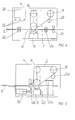
- FIG. 4 schematically shows a stripping device installed in a housing 14, that according to the figures 1 to 3 explained principle works.
- the double arrow next to the pressure device 6 illustrates their pushing motion of the ribbon cable 8 against the pulley 6 with the Volume 2 to achieve the desired friction pressure or Release of the ribbon cable after stripping.
- Volume 2 is guided over two further pulleys 16 and 18, of which one connected to a drive motor, not shown here can be to the circulating belt 2 in the required To move.
- a stripping device 20 is used Remove the plastic material from the belt 2. For example, it can be in the form of a brush.
- the tape 2 does not necessarily have to be in the form of a triangle be performed, as the drawings indicate, but it could only be performed on the two rollers 4 and 16 are, as indicated in Fig. 4.
- the one drawn next to it Double arrow illustrates the possibility of Frictional pressure due to the adjustability of the roller arrangement instead to produce the pressure device 6.
- Fig. 5 shows a device for stripping the ends of a Ribbon conductor, with an adjustable length stop 32nd is provided, on which the end of the ribbon conductor rests. This is clamped in a clamping device 34, the Clamping movement is indicated by vertical double arrows and in the direction of the horizontal double arrow using a Displacement drive 36 displaceable in the longitudinal direction of the belt is. This allows the ribbon cable to be placed over the desired one Stripping length through the friction area - program controlled - move.
- the stripping device for the insulating material carried by the tape 2 is in two parts in this embodiment formed: a scraper 20b in the form of a blade, one Spatula or the like. First removes the main mass of the Ribbon conductor removed insulation material, and a subsequent one Brush 20a provides for the cleaning of the belt 2.
- the scraper 20b with the length stop 32 can be combined, as shown in FIG. 5.
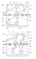
- the pressure device 6 shows an embodiment for stripping on both sides a ribbon cable, in which an additional one Ribbon / roller arrangement on the other side of the ribbon conductor is provided.
- the pressure device 6 can be here omitted, since one of the deflection rollers 4, 4a, as a pressure device works for the other.
- the vertical double arrows illustrate the adjustability of one or both Arrangements to the desired friction pressure. How it works corresponds to what has already been said above.
- FIG. 8 is a side view of a stripping device shown, which corresponds approximately to that of FIG. 4 and is therefore provided with the same reference numbers.
- the removal of the insulating material can also with the help of an abrasive disk 38, which is shown in the Example on its circumference with a plastic shot coating is provided, which is the friction and removal effect compared to, for example, a leather covering of the pane improved even further.
- the abrasive disc 38 can either Correspond to the total width of the ribbon cable to be stripped, or as wide as a single flat conductor, to expose only individual conductors.
- the disc can also be in Direction of the double arrow X over several single conductors or traversed over the entire width of the ribbon cable, to expose more than one leader.
- the double arrow Y indicates a height adjustment of the abrasive disc 38 or Tape guide mechanism.
- FIG. 9 shows an embodiment of a removal disk 40 with several raised work surfaces 42, the width of the respective Width of the flat conductor to be exposed of the one shown below Ribbon conductor 8 corresponds.
- the one between the ladders insulation is designated 44.
- the embodiment is the abrasive disc 38 or 40 on her Scope coated with plastic shot, as by the dotting indicated.
- a correspondingly provided with plastic shot Volume 2 is illustrated in FIG. 10.
- Plastic shot can also be natural shot, for example Corn grist, use to the desired erosion without Damage to the thin copper flat conductors or their tinning to achieve.
- the thickness of the shot coating is aimed the required tool life, which if desired, the entire volume of the shot can be enforced.
Landscapes
- Removal Of Insulation Or Armoring From Wires Or Cables (AREA)
- Manufacture Of Motors, Generators (AREA)
Abstract
Description
- Fig. 1 bis 3
- schematische Darstellungen von drei Bearbeitungsphasen zur Erläuterung des Prinzips der Erfindung;
- Fig. 4
- eine schematische Darstellung eines Ausführungsbeispiels der Erfindung zur Freilegung eines Fensters im Flachbandleiter;
- Fig. 5
- ein anderes Ausführungsbeispiel der Erfindung zur Abisolierung eines Endes des Flachbandleiters;
- Fig. 6
- ein Ausführungsbeispiel der Erfindung zur doppelseitigen Abisolierung des Flachbandleiters;
- Fig. 7
- ein gegenüber Figur 6 abgewandeltes Ausführungsbeispiel der Erfindung;
- Fig. 8
- eine schematische Ansicht einer der Vorrichtung nach Fig. 4 ähnlichen Ausführungsform der Erfindung von einer anderen Seite;
- Fig. 9
- ein erfindungsgemäßes Abtragwerkzeug in Form einer Walze; und
- Fig. 10
- ein erfindungsgemäßes Abtragwerkzeug in Form eines Bandes.
Claims (15)
- Vorrichtung zum Abisolieren von Flachbandleitern mit mehreren parallel nebeneinander in einer Kunststoffisolierung eingebetteten metallischen Leiterbahnen, mit einem Werkzeug zum Abtragen des Kunststoffmaterials der Isolierung unter Freilegung der Leiterbahnen, dadurch gekennzeichnet, dass die relativ zu dem Flachbandleiter (8) bewegbare aktive Arbeitsfläche des Abtragwerkzeugs (Band 2) durch ein Material geringerer Härte als diejenige des Leiterbahnmaterials (10) gebildet wird.
- Vorrichtung nach Anspruch 1, dadurch gekennzeichnet, dass die Arbeitsfläche einen Belag aus Kunststoffschrot aufweist.
- Vorrichtung nach Anspruch 1, dadurch gekennzeichnet, dass die Arbeitsfläche eine Reibfläche ist.
- Vorrichtung nach Anspruch 2 oder 3, dadurch gekennzeichnet, dass die Arbeitsfläche durch ein umlaufendes Band (2) gebildet wird.
- Vorrichtung nach Anspruch 4, gekennzeichnet durch eine den Flachbandleiter (8) gegen die Arbeitsfläche drückende Andruckvorrichtung (6).
- Vorrichtung nach Anspruch 4, gekennzeichnet durch eine Abstreifvorrichtung (20,20a,20b) für mitgenommenes Isoliermaterial von der Reibfläche.
- Vorrichtung nach Anspruch 5, dadurch gekennzeichnet, dass die Andruckvorrichtung (6) einer Umlenkwalze (4) des Reibbandes (2) gegenüberliegend angeordnet ist.
- Vorrichtung nach Anspruch 1, 2 oder 3, dadurch gekennzeichnet, dass das Abtragwerkzeug mindestens eine rotierende Scheibe/Walze aufweist.
- Vorrichtung nach Anspruch 8, dadurch gekennzeichnet, dass die Reibfläche aus Leder besteht.
- Vorrichtung nach einem der vorstehenden Ansprüche, dadurch gekennzeichnet, dass das Abtragwerkzeug zwei beiderseits des zwischen ihnen geführten Flachbandleiters (8) angeordnete Abtragflächen (Reibbänder 2,2') aufweist.
- Vorrichtung nach Anspruch 10, dadurch gekennzeichnet, dass die Abtragflächen einander gegenüberliegend angeordnet sind (Fig. 6).
- Vorrichtung nach Anspruch 10, dadurch gekennzeichnet, dass die Abtragflächen in Längsrichtung des Flachbandleiters (8) gegeneinander versetzt angeordnet sind und jeder Abtragfläche eine Andruckvorrichtung (6,6') gegenüberliegt.
- Vorrichtung nach Anspruch 11 oder 12, dadurch gekennzeichnet, dass die Reibflächen durch über Umlenkwalzen (4) laufende Teile des Reibbandes (2) gebildet werden.
- Vorrichtung nach einem der vorstehenden Ansprüche, gekennzeichnet durch eine Spannvorrichtung (34) zum Einspannen des Flachbandleiters (8), einen Verschiebungsantrieb (36) zum Verschieben der Spannvorrichtung (34) in Längsrichtung des Flachbandleiters (8) und einen verstellbaren Längenanschlag (32) für ein abgeschnittenes Ende des Flachbandleiters.
- Verfahren zum Abisolieren von Flachbandleitern mit mehreren parallel nebeneinander in einer Kunststoffisolierung eingebetteten Metallleiterbahnen, bei welchem das Kunststoffmaterial der Isolierung mit einem Werkzeug partiell so weit abgetragen wird, dass die Leiterbahnen freigelegt werden, dadurch gekennzeichnet, dass das Kunststoffmaterial durch Reibung bis zum Erweichen erwärmt und dann abgewischt wird.
Applications Claiming Priority (2)
| Application Number | Priority Date | Filing Date | Title |
|---|---|---|---|
| DE2003123495 DE10323495B3 (de) | 2003-05-23 | 2003-05-23 | Verfahren und Vorrichtung zum Abisolieren von Flachbandleitern |
| DE10323495 | 2003-05-23 |
Publications (2)
| Publication Number | Publication Date |
|---|---|
| EP1480308A2 true EP1480308A2 (de) | 2004-11-24 |
| EP1480308A3 EP1480308A3 (de) | 2006-02-08 |
Family
ID=32731184
Family Applications (1)
| Application Number | Title | Priority Date | Filing Date |
|---|---|---|---|
| EP04010714A Withdrawn EP1480308A3 (de) | 2003-05-23 | 2004-05-05 | Verfahren und Vorrichtung zum Abisolieren von Flachbandleitern |
Country Status (2)
| Country | Link |
|---|---|
| EP (1) | EP1480308A3 (de) |
| DE (1) | DE10323495B3 (de) |
Cited By (1)
| Publication number | Priority date | Publication date | Assignee | Title |
|---|---|---|---|---|
| WO2022171384A1 (de) * | 2021-02-10 | 2022-08-18 | Wafios Aktiengesellschaft | Verfahren und drahtverarbeitungsmaschine zur herstellung von formteilen aus isoliertem flachmaterial |
Families Citing this family (3)
| Publication number | Priority date | Publication date | Assignee | Title |
|---|---|---|---|---|
| RU2280302C1 (ru) * | 2004-12-24 | 2006-07-20 | Федеральное государственное унитарное предприятие "Муромский приборостроительный завод" (ФГУП "МПЗ") | Автомат изготовления мотков провода |
| DE102007050239A1 (de) * | 2007-10-20 | 2009-04-23 | Tyco Electronics Amp Gmbh | Verfahren zum Abisolieren eines Flachbandkabels an seinem freien Ende bzw. innerhalb des Flachbandkabels |
| CN114362061B (zh) * | 2021-12-22 | 2023-09-19 | 江苏安诚电缆有限公司 | 一种阻燃橡套电缆用绝缘保护层剥离设备 |
Family Cites Families (10)
| Publication number | Priority date | Publication date | Assignee | Title |
|---|---|---|---|---|
| US3346897A (en) * | 1964-08-03 | 1967-10-17 | Lockheed Aircraft Corp | Flat conductor cable stripping machine |
| GB1209311A (en) * | 1967-01-02 | 1970-10-21 | Mini Of Technology London | Improvements in or relating to tape cable stripping |
| US3385140A (en) * | 1967-06-15 | 1968-05-28 | Carpenter Mfg Co Inc | Flat multi-conductor stripping apparatus |
| DE2327620A1 (de) * | 1973-05-28 | 1974-12-19 | Siemens Ag | Verfahren und vorrichtung zum abtragen extrudierter leitschichten an elektrischen kabeln und leitungen |
| US4597176A (en) * | 1981-06-22 | 1986-07-01 | Shields Charles E | Method for removing insulation from flat cable |
| JPH05184032A (ja) * | 1991-12-26 | 1993-07-23 | Tokyo Electric Power Co Inc:The | 線条体ブラッシング装置と同装置を用いた高圧引下線工事用ロボット |
| DE50109839D1 (de) * | 2000-02-11 | 2006-06-29 | Komax Holding Ag | Verfahren und Einrichtung zur Abisolierung eines Flachkabels |
| DE10017036C2 (de) * | 2000-04-05 | 2003-07-24 | Schleuniger Holding Ag Thun | Verfahren und Vorrichtung zum partiellen Freilegen der Leiterbahnen in Flachleiter-Bandkabeln |
| WO2001099250A1 (de) * | 2000-06-23 | 2001-12-27 | Schleuniger Holding Ag | Vorrichtung zum abisolieren von flachbandkabeln |
| GB2370426B (en) * | 2000-12-22 | 2003-07-09 | Antech Ltd | Cable stripping apparatus |
-
2003
- 2003-05-23 DE DE2003123495 patent/DE10323495B3/de not_active Expired - Fee Related
-
2004
- 2004-05-05 EP EP04010714A patent/EP1480308A3/de not_active Withdrawn
Cited By (1)
| Publication number | Priority date | Publication date | Assignee | Title |
|---|---|---|---|---|
| WO2022171384A1 (de) * | 2021-02-10 | 2022-08-18 | Wafios Aktiengesellschaft | Verfahren und drahtverarbeitungsmaschine zur herstellung von formteilen aus isoliertem flachmaterial |
Also Published As
| Publication number | Publication date |
|---|---|
| EP1480308A3 (de) | 2006-02-08 |
| DE10323495B3 (de) | 2004-08-19 |
Similar Documents
| Publication | Publication Date | Title |
|---|---|---|
| DE1782447C3 (de) | Vorrichtung zum Reinigen der Seitenflächen einer Kreismesserscheibe für das Schneiden eines Zigarettenstranges od. dgl. im Bereich der Schneidkanten | |
| EP0070554B1 (de) | Handgerät zum Abschälen der äusseren Mantelschicht elektrischer Leitungen und elektrischer Kabel | |
| EP3811478B1 (de) | Vorrichtung und verfahren zum abisolieren von kabeln | |
| EP2127838B1 (de) | Einrichtung zum Positionieren und Lageerhalten von dünnen Substraten am geschnittenen Substratblock | |
| DE112017004840T5 (de) | Rotative Abisoliervorrichtung | |
| DE3309557A1 (de) | Rakel fuer eine walzenwaschvorrichtung | |
| DE2232714C3 (de) | Gerät zum Abisolieren in einem mehradrigen elektrischen Flachkabel zusammenhängender isolierter Adern | |
| DE102007029918B4 (de) | Bearbeitungsaggregat | |
| EP0999015A2 (de) | Bahnschneidvorrichtung mit einer integrierten Messeranordnung in einer Rollenrotationsdruckmaschine | |
| DE10323495B3 (de) | Verfahren und Vorrichtung zum Abisolieren von Flachbandleitern | |
| DE2825301A1 (de) | Vorrichtung zur herstellung eines waermegedaemmten verbundprofils | |
| DE102016011683A1 (de) | Vorrichtung zum Schleifen der Seitenkanten eines Wintersportgerätes | |
| DE3137616C2 (de) | ||
| DE102013100768A1 (de) | Vorrichtung und Verfahren zum Schneiden von Tabak von einem Tabakkuchen | |
| EP1294062B1 (de) | Vorrichtung zur Entfernung einer Isolierstoffschicht von einem Flachbandleiter | |
| AT520720B1 (de) | Klemmvorrichtung zum Festlegen an einer Glasscheibe | |
| DE29816176U1 (de) | Vorrichtung zum Vorbehandeln der Oberfläche einer abzulösenden Tapete | |
| DE2709367C2 (de) | Kurzfrontabbaumaschine für Grubenarbeiten | |
| DE102015206855B4 (de) | Vorrichtung und Verfahren zur spanlosen Bearbeitung einer geraden Kante an einer Platte | |
| DE1632148B1 (de) | Maschine zum Entrippen und Glätten von Tabakblättern | |
| DE2626410C2 (de) | Verfahren und Vorrichtung zum Vernichten fotografischer Materialien | |
| DE19515880C1 (de) | Vorrichtung zum Entfernen des Mantels von ummantelten Leitern oder Kabeln | |
| EP0391112A2 (de) | Vorrichtung zum Enthäuten von Fischen | |
| DE2259877C3 (de) | Vorrichtung zum Schnitzeln von Schokolade | |
| DE10160803C1 (de) | Verfahren und Vorrichtung zum partiellen Freilegen einer Leiterbahn in einem mehradrigen Flachbandkabel |
Legal Events
| Date | Code | Title | Description |
|---|---|---|---|
| PUAI | Public reference made under article 153(3) epc to a published international application that has entered the european phase |
Free format text: ORIGINAL CODE: 0009012 |
|
| AK | Designated contracting states |
Kind code of ref document: A2 Designated state(s): AT BE BG CH CY CZ DE DK EE ES FI FR GB GR HU IE IT LI LU MC NL PL PT RO SE SI SK TR |
|
| AX | Request for extension of the european patent |
Extension state: AL HR LT LV MK |
|
| PUAL | Search report despatched |
Free format text: ORIGINAL CODE: 0009013 |
|
| AK | Designated contracting states |
Kind code of ref document: A3 Designated state(s): AT BE BG CH CY CZ DE DK EE ES FI FR GB GR HU IE IT LI LU MC NL PL PT RO SE SI SK TR |
|
| AX | Request for extension of the european patent |
Extension state: AL HR LT LV MK |
|
| AKX | Designation fees paid | ||
| STAA | Information on the status of an ep patent application or granted ep patent |
Free format text: STATUS: THE APPLICATION IS DEEMED TO BE WITHDRAWN |
|
| 18D | Application deemed to be withdrawn |
Effective date: 20060809 |
|
| REG | Reference to a national code |
Ref country code: DE Ref legal event code: 8566 |