EP1480322A2 - Steuerverfahren für einen Stromrichter - Google Patents
Steuerverfahren für einen Stromrichter Download PDFInfo
- Publication number
- EP1480322A2 EP1480322A2 EP04008990A EP04008990A EP1480322A2 EP 1480322 A2 EP1480322 A2 EP 1480322A2 EP 04008990 A EP04008990 A EP 04008990A EP 04008990 A EP04008990 A EP 04008990A EP 1480322 A2 EP1480322 A2 EP 1480322A2
- Authority
- EP
- European Patent Office
- Prior art keywords
- voltage
- current
- converter
- transformer
- control method
- Prior art date
- Legal status (The legal status is an assumption and is not a legal conclusion. Google has not performed a legal analysis and makes no representation as to the accuracy of the status listed.)
- Granted
Links
Images


Classifications
-
- H—ELECTRICITY
- H02—GENERATION; CONVERSION OR DISTRIBUTION OF ELECTRIC POWER
- H02M—APPARATUS FOR CONVERSION BETWEEN AC AND AC, BETWEEN AC AND DC, OR BETWEEN DC AND DC, AND FOR USE WITH MAINS OR SIMILAR POWER SUPPLY SYSTEMS; CONVERSION OF DC OR AC INPUT POWER INTO SURGE OUTPUT POWER; CONTROL OR REGULATION THEREOF
- H02M5/00—Conversion of AC power input into AC power output, e.g. for change of voltage, for change of frequency, for change of number of phases
- H02M5/02—Conversion of AC power input into AC power output, e.g. for change of voltage, for change of frequency, for change of number of phases without intermediate conversion into DC
- H02M5/04—Conversion of AC power input into AC power output, e.g. for change of voltage, for change of frequency, for change of number of phases without intermediate conversion into DC by static converters
- H02M5/22—Conversion of AC power input into AC power output, e.g. for change of voltage, for change of frequency, for change of number of phases without intermediate conversion into DC by static converters using discharge tubes with control electrode or semiconductor devices with control electrode
- H02M5/25—Conversion of AC power input into AC power output, e.g. for change of voltage, for change of frequency, for change of number of phases without intermediate conversion into DC by static converters using discharge tubes with control electrode or semiconductor devices with control electrode using devices of a thyratron or thyristor type requiring extinguishing means
- H02M5/27—Conversion of AC power input into AC power output, e.g. for change of voltage, for change of frequency, for change of number of phases without intermediate conversion into DC by static converters using discharge tubes with control electrode or semiconductor devices with control electrode using devices of a thyratron or thyristor type requiring extinguishing means for conversion of frequency
Definitions
- the invention relates to a control method for a converter, built as a two- or three-phase bridge circuit is, with bridge branches made of any number identical bipoles exist, each an internal Have energy storage and at different controllable Switching states a different terminal voltage exhibit.
- Such converters are together with one Medium frequency transformer particularly suitable for power supply of rail vehicles and should Replace traction transformer operated with mains frequency. However, you can also, together with a medium frequency transformer, also for the power supply of stationary Facilities are used.
- a modular high-voltage converter has already been built proposed in full bridge circuit, its bridge branches from the series connection of any number of There are two poles (submodules), the two poles at different controllable switching states a different Have terminal voltage.
- the bridge exit is preferred connected to a medium frequency transformer, the Frequency is significantly higher than the network frequency.
- the submodules have an internal energy storage (capacitor) and are designed so that their terminal voltage is independent of the current direction a positive or negative value or can assume the value zero. With the submodules are stepped Tensions both on the network side and on the medium frequency side realized.
- the primary voltage of the medium frequency transformer is without additional control elements to a constant effective value controlled and stabilized.
- the structure allows a strictly modular implementation of the Converter.
- the converter can do so in a simple manner be interpreted that it with different network frequencies and voltages can be operated, so that a multi-system use is made possible.
- Each of the four converter branches must have a voltage means with regard to the number of submodules that it is the sum of half the mains voltage amplitude (inclusive the tolerances of the mains voltage) and half the transformer voltage amplitude, which is based on the nominal value of the mains voltage amplitude oriented, can muster.
- a converter phase Series connection of two converter branches in terms of voltage, therefore, about twice the mains voltage amplitude dimension, although only the mains voltage amplitude must fall off. It must therefore be significantly oversized be what's in a large number of submodules manifests.
- a disadvantage of the high-voltage converters described above are the high effort for controlling the large number of submodules as well as the effort for high-voltage insulation.
- the invention has for its object a control method to specify for a converter of the type described at the outset, with which the effort for the converter through reduction the number of submodules can be minimized.
- the current amplitude of the output voltage is on the bridge diagonal to a value in the range up to the maximum possible voltage amplitude from the current sum the voltages of the internal energy storage of the bipoles and is dependent on the current mains voltage value.
- the invention takes advantage of the possibility that the Total voltage of the energy storage (capacitors) in the Submodules can have a value that is the same or, if necessary is even greater than the mains voltage.
- the pulsating with double mains frequency Power of the single-phase network is in the capacitors Submodules temporarily stored. Through the control process however, there will be a change in power flow through the medium frequency transformer reached.
- the conditions in the zero voltage crossing are different of the network.
- control so that the current amplitudes in the individual converter branches approximately over time are the same size. This will be a good one because of the Current load more uniform utilization of the semiconductor components reached.
- control procedure is for the converters described above in full-bridge circuit and in half-bridge circuit alike applicable.
- transformer secondary voltage is, for example, by a four-quadrant controller connected to a DC link connected, rectified.
- circuit variants with several secondary windings and several four-quadrant units are also possible. The same applies to the number of DC voltage intermediate circuits.
- the control of the converter branches takes place in such a way that the terminal voltage of a submodule gradually the capacitor voltage is switched on or off.
- the number of Voltage levels depend on the number of submodules. The leave mains voltage and the medium frequency voltage independent of frequency, phase position and amplitude of each other.
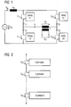
- Figure 1 first shows the general structure of the converter in a version as a full bridge circuit.
- the line voltage u N is present at the input of the converter.
- Four converter branches 11, 12, 21 and 22 are arranged in the form of a bridge circuit.
- a medium frequency transformer T with the primary voltage u T and the secondary voltage u T ' is located on the bridge diagonal.
- the converter branches 11, 12, 21, 22 each consist of several submodules with the terminal voltage u x1 ... u xn .
- FIG. 3 A possible implementation of a submodule is shown in FIG. 3.
- the submodule is in the form of a full-bridge circuit of a voltage converter, only that it is used here as a single two-pole connection.
- the bridge circuit consists of four power semiconductor switches IGBT1 ... IGBT4 with anti-parallel diodes D1 ... D4.
- a capacitor C which is charged to the voltage U d , is connected to the DC connections of the bridge circuit. Switching the power semiconductor switches IGBT1 ... IGBT4 creates switching states with which the terminal voltage u x , regardless of the direction of the current i z , becomes positive, negative or even zero (short circuit).
- the voltage u 11 , u 12 , u 21 , u 22 of a converter branch 11, 12, 21, 22 assume the value range -n U 0 ... + nU 0 and can therefore be set in discrete "stair steps" of the voltage U 0 .
- FIG. 4 shows a basic vibration equivalent circuit diagram of the converter according to FIG. 1. This is based on a mains frequency of 16 2/3 Hz, i.e. a period of 60 ms, and a transformer frequency of 300 Hz.
- FIG. 5 shows the line voltage u N and the line current i N
- FIG. 6 shows the time profile of the line power p N and the energy pulsating at twice the line frequency.
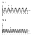
- FIG. 7 shows exemplary time profiles of the fundamental oscillations of transformer primary voltage u T and primary current i T.
- the converter or converters on the secondary side are controlled such that the fundamental oscillations of current and voltage are in phase on the primary side.
- the time profiles of the transformer power p T and of the transformer power averaged over a period of the fundamental transformer wave are shown in FIG.
- the converter branches 11, 12, 21, 22 can be embossed Voltage sources are considered, the submodules so can be controlled according to the previous method that following fundamental oscillation voltages for the converter branches 11, 12, 21, 22 result in:
- u N are the fundamental oscillation of the mains voltage and u T the fundamental oscillation of the transformer primary voltage.
- i N is the fundamental oscillation of the mains current
- i T the fundamental oscillation of the transformer primary current
- Each of the four converter branches 11, 12, 21, 22 must be designed in terms of voltage, i.e. with regard to the number of submodules, in such a way that it is the sum of half the mains voltage amplitude (including the tolerances of the mains voltage u N ) and half the transformer voltage amplitude, which is equal to the nominal value oriented to the mains voltage amplitude.
- a converter phase (series connection of two converter branches 11, 12 or 21, 22) is therefore to be dimensioned in terms of voltage to approximately twice the mains voltage amplitude, although only the mains voltage amplitude has to drop there. It must therefore be significantly oversized, which manifests itself in a large number of submodules.
- the current amplitude of the output voltage on the bridge diagonal is controlled to a value in the range up to the maximum possible voltage amplitude, which is dependent on the current sum of the voltages of the capacitors C of the submodules and the current value of the mains voltage u N ,
- FIG. 11 shows exemplary time profiles of the fundamental oscillations of transformer primary voltage u T and transformer primary current i T.
- the control can take place such that the fundamental oscillations of current and voltage are in phase on the primary side.
- the control of the secondary converter or converters takes place in such a way that the power flow shown in FIG. 12 is established. This can be achieved by a corresponding phase shift between the primary and secondary voltage on the transformer T.
- the individual converter branches 11, 12, 21, 22 can be regarded as impressed voltage sources, the submodules being controlled in such a way that the following fundamental oscillation voltages result for the converter branches 11, 12, 21, 22:
- the control can expediently take place again in such a way that the fundamental oscillations of the mains voltage u N and mains current i N have the same phase position.
- the time profiles of branch voltage u 11 and branch current i 11 are shown in FIG. The uniform utilization with regard to current and voltage can be seen there.
- the branch power p 11 u 11 * i 11 and the pulsating portion of the associated energy are shown in FIG. 14. The energy that is pulsed by a factor of 2 compared to the example shown in FIG.
- FIGS. 15 and 16 show a comparison of the previous control with the control according to the invention with regard to the sum of the capacitor voltages u d ⁇ and u d ⁇ 'of the submodules of a converter branch 11, 12, 21, 22.
- For the transformer primary voltage u T is the difference of half the mains voltage u N / 2 and the sum of the capacitor voltages u d ⁇ of the submodules of the branch can be used. If the capacitor voltages u d , as shown in FIG.
- the control method according to the invention enables the Control, energy supply and high-voltage insulation costs by reducing the number of submodules reduce.
- control method is expanded so that instead of a constant fundamental oscillation of the transformer primary current i T, this is carried out in such a way that a time curve of the current amount is set in the branches, which has approximately the same maximum values over time, an additional effort reduction can be achieved.
Landscapes
- Engineering & Computer Science (AREA)
- Power Engineering (AREA)
- Ac-Ac Conversion (AREA)
- Inverter Devices (AREA)
- Power Conversion In General (AREA)
- Control Of Motors That Do Not Use Commutators (AREA)
- Dc-Dc Converters (AREA)
Abstract
Description
- Figur 1
- den Aufbau des Stromrichters in Vollbrückenschaltung;
- Figur 2
- die Aufteilung eines Stromrichterzweiges in einzelne Submodule;
- Figur 3
- eine mögliche Realisierung für ein einzelnes Submodul;
- Figur 4
- ein Grundschwingungs-Ersatzschaltbild für den Stromrichter gemäß Figur 1;
- Figur 5
- den Zeitverlauf der Grundschwingungen von Netzspannung und Netzstrom mit dem bisherigen Verfahren;
- Figur 6
- den zugehörigen Zeitverlauf der Netzleistung und der mit doppelter Netzfrequenz pulsierenden Energie;
- Figur 7
- den zugehörigen Zeitverlauf der Grundschwingung von Transformatorspannung und -strom;
- Figur 8
- den zugehörigen Zeitverlauf der Transformatorleistung und deren über eine Periode der Transformatorgrundfrequenz gemittelten Wert;
- Figur 9
- den zugehörigen Zeitverlauf von Zweigspannung und Zweigstrom;
- Figur 10
- den zugehörigen Zeitverlauf von Zweigleistung und pulsierender Energie;
- Figur 11
- den Zeitverlauf der Grundschwingungen von Transformatorprimärspannung und -strom nach dem erfindungsgemäßen Steuerverfahren;
- Figur 12
- den zugehörigen Zeitverlauf der Transformatorleistung und deren über eine Periode der Transformatorgrundfrequenz gemittelten Wert;
- Figur 13
- den zugehörigen Zeitverlauf von Zweigspannung und Zweigstrom und
- Figur 14
- den zugehörigen Zeitverlauf von Zweigleistung und pulsierender Energie.
- Figur 15
- bzw.
- Figur 16
- den Vergleich der bisherigen mit der erfindungsgemäßen Ansteuerung bezüglich der Summe der Kondensatorspannungen udΣ bzw. udΣ.
Claims (3)
- Steuerverfahren für einen Stromrichter, der als zwei- oder dreiphasige Brückenschaltung aufgebaut ist, mit Brückenzweigen, die aus einer beliebigen Anzahl identischer Zweipole bestehen, die jeweils einen internen Energiespeicher aufweisen und bei verschiedenen steuerbaren Schaltzuständen eine unterschiedliche Klemmenspannung aufweisen, dadurch gekennzeichnet, dass die aktuelle Amplitude der Ausgangsspannung (U0) an der Brückendiagonale auf einen Wert im Bereich bis zur maximal möglichen Spannungsamplitude, die von der aktuellen Summe der Spannungen der internen Energiespeicher der Zweipole und dem aktuellen Netzspannungswert abhängig ist, gesteuert wird.
- Steuerverfahren nach Anspruch 1, dadurch gekennzeichnet, dass die Stromamplituden in den einzelnen Stromrichterzweigen (11, 12, 21, 22) so gesteuert werden, dass sie über der Zeit näherungsweise gleich groß sind.
- Steuerverfahren nach einem der vorhergehenden Ansprüche, dadurch gekennzeichnet, dass die Ausgangsspannung (U0) der Brückendiagonale auf einen Mittelfrequenztransformator geführt wird, dessen Sekundärwicklung(en) mit mindestens einem Spannungsumrichter beschaltet ist.
Applications Claiming Priority (2)
| Application Number | Priority Date | Filing Date | Title |
|---|---|---|---|
| DE10323009 | 2003-05-21 | ||
| DE10323009A DE10323009A1 (de) | 2003-05-21 | 2003-05-21 | Steuerverfahren für einen Stromrichter |
Publications (3)
| Publication Number | Publication Date |
|---|---|
| EP1480322A2 true EP1480322A2 (de) | 2004-11-24 |
| EP1480322A3 EP1480322A3 (de) | 2006-06-07 |
| EP1480322B1 EP1480322B1 (de) | 2008-07-02 |
Family
ID=33039250
Family Applications (1)
| Application Number | Title | Priority Date | Filing Date |
|---|---|---|---|
| EP04008990A Expired - Lifetime EP1480322B1 (de) | 2003-05-21 | 2004-04-15 | Steuerverfahren für einen Stromrichter |
Country Status (3)
| Country | Link |
|---|---|
| EP (1) | EP1480322B1 (de) |
| AT (1) | ATE400079T1 (de) |
| DE (2) | DE10323009A1 (de) |
Cited By (1)
| Publication number | Priority date | Publication date | Assignee | Title |
|---|---|---|---|---|
| CN107696873A (zh) * | 2017-10-23 | 2018-02-16 | 西南交通大学 | 一种动车组牵引传动供电系统 |
Family Cites Families (1)
| Publication number | Priority date | Publication date | Assignee | Title |
|---|---|---|---|---|
| GB2294821A (en) * | 1994-11-04 | 1996-05-08 | Gec Alsthom Ltd | Multilevel converter |
-
2003
- 2003-05-21 DE DE10323009A patent/DE10323009A1/de not_active Withdrawn
-
2004
- 2004-04-15 AT AT04008990T patent/ATE400079T1/de active
- 2004-04-15 EP EP04008990A patent/EP1480322B1/de not_active Expired - Lifetime
- 2004-04-15 DE DE502004007472T patent/DE502004007472D1/de not_active Expired - Lifetime
Cited By (2)
| Publication number | Priority date | Publication date | Assignee | Title |
|---|---|---|---|---|
| CN107696873A (zh) * | 2017-10-23 | 2018-02-16 | 西南交通大学 | 一种动车组牵引传动供电系统 |
| CN107696873B (zh) * | 2017-10-23 | 2023-12-22 | 西南交通大学 | 一种动车组牵引传动供电系统 |
Also Published As
| Publication number | Publication date |
|---|---|
| EP1480322A3 (de) | 2006-06-07 |
| DE10323009A1 (de) | 2004-12-16 |
| ATE400079T1 (de) | 2008-07-15 |
| EP1480322B1 (de) | 2008-07-02 |
| DE502004007472D1 (de) | 2008-08-14 |
Similar Documents
| Publication | Publication Date | Title |
|---|---|---|
| EP2391522B1 (de) | DC/DC-Wandler und AC/DC-WANDLER | |
| EP1311058B1 (de) | Frequenzumrichter | |
| EP1145416B1 (de) | Umrichter für die umformung von elektrischer energie | |
| DE19630284A1 (de) | Antriebssystem für ein Schienenfahrzeug und Ansteuerverfahren hierzu | |
| EP2299572A1 (de) | Aufstarten eines DC/DC-Wandlers mit Hochfrequenztransformator | |
| EP2678933B1 (de) | Verfahren zur erzeugung einer ausgangsspannung an einem modularen mehrstufigem stromrichter und anordnung zur durchführung des verfahrens | |
| EP2067227B1 (de) | Antriebsenergieversorgung bei schienenfahrzeugen | |
| EP2421135B1 (de) | Transformatorlose wechselrichter-schaltungsanordnung mit tiefsetzstellerschaltung | |
| WO2014206704A1 (de) | Umrichteranordnung mit parallel geschalteten mehrstufen-umrichtern sowie verfahren zu deren steuerung | |
| CH693523A5 (de) | Einrichtung zur Begrenzung der Aenderungsgeschwindigkeit der ausgangsseitigen Spannung eines selbstgeführten mehrphasigen Umrichters. | |
| EP0952030B1 (de) | Elektrische Schaltungsanordnung zum Versorgen eines elektrischen Antriebssystems | |
| EP1211788A1 (de) | Bedämpfung von Resonanzüberhöhungen bei einem an einem Umrichter mit Spannungszwischenkreis betriebenen elektrischen Motor | |
| EP0743744B1 (de) | Stromrichter | |
| DE19941170A1 (de) | Selbstsymmetrierende Einspeiseschaltung | |
| DE4344709C2 (de) | Verfahren zur Umwandlung von unterschiedlich großen Gleich- oder Wechselspannungen in eine beliebig vorgegebene Spannung | |
| EP0534242B1 (de) | Verfahren zur Reduzierung von Spannungsschwingungen eines Zwischenkreismittenanschlusses eines Dreipunktumrichters | |
| CH691720A5 (de) | Einrichtung zur Begrenzung der Aenderungsgeschwindigkeit von Strömen und Spannungen zwischen Leitungen oder gegenüber dem Erdpotential und Verwendung derselben. | |
| EP1480322B1 (de) | Steuerverfahren für einen Stromrichter | |
| DE102020106349A1 (de) | Elektrische Schaltungsanordnung und Kraftfahrzeug | |
| EP1315180A1 (de) | Transformator und Einspeiseschaltung für Mehrsystem-Triebfahrzeuge | |
| DE202024102847U1 (de) | Leistungswandler zur Umwandlung von mehrphasiger Wechselstrom-Netzeingangsleistung in Gleichstrom-Ausgangsleistung und Wasserstoffproduktionsanlage | |
| DE10323503A1 (de) | Stromrichter | |
| EP4309277A1 (de) | Verfahren zum betrieb eines gleichstromstellers zur versorgung einer elektrolyseeinrichtung mit elektrischer betriebsenergie | |
| DE10323218A1 (de) | Hochspannungsumrichter und Verfahren zu seiner Ansteuerung | |
| DE3724639C2 (de) | Netzgerät für einen Ozonerzeuger |
Legal Events
| Date | Code | Title | Description |
|---|---|---|---|
| PUAI | Public reference made under article 153(3) epc to a published international application that has entered the european phase |
Free format text: ORIGINAL CODE: 0009012 |
|
| AK | Designated contracting states |
Kind code of ref document: A2 Designated state(s): AT BE BG CH CY CZ DE DK EE ES FI FR GB GR HU IE IT LI LU MC NL PL PT RO SE SI SK TR |
|
| AX | Request for extension of the european patent |
Extension state: AL HR LT LV MK |
|
| PUAL | Search report despatched |
Free format text: ORIGINAL CODE: 0009013 |
|
| AK | Designated contracting states |
Kind code of ref document: A3 Designated state(s): AT BE BG CH CY CZ DE DK EE ES FI FR GB GR HU IE IT LI LU MC NL PL PT RO SE SI SK TR |
|
| AX | Request for extension of the european patent |
Extension state: AL HR LT LV MK |
|
| RIC1 | Information provided on ipc code assigned before grant |
Ipc: H02M 5/297 20060101AFI20060425BHEP Ipc: H02M 5/27 20060101ALI20060425BHEP |
|
| 17P | Request for examination filed |
Effective date: 20061207 |
|
| AKX | Designation fees paid |
Designated state(s): AT CH DE FR IT LI SE |
|
| 17Q | First examination report despatched |
Effective date: 20070125 |
|
| GRAP | Despatch of communication of intention to grant a patent |
Free format text: ORIGINAL CODE: EPIDOSNIGR1 |
|
| GRAS | Grant fee paid |
Free format text: ORIGINAL CODE: EPIDOSNIGR3 |
|
| GRAA | (expected) grant |
Free format text: ORIGINAL CODE: 0009210 |
|
| AK | Designated contracting states |
Kind code of ref document: B1 Designated state(s): AT CH DE FR IT LI SE |
|
| REG | Reference to a national code |
Ref country code: CH Ref legal event code: NV Representative=s name: SIEMENS SCHWEIZ AG Ref country code: CH Ref legal event code: EP |
|
| REF | Corresponds to: |
Ref document number: 502004007472 Country of ref document: DE Date of ref document: 20080814 Kind code of ref document: P |
|
| REG | Reference to a national code |
Ref country code: SE Ref legal event code: TRGR |
|
| REG | Reference to a national code |
Ref country code: CH Ref legal event code: PCAR Free format text: SIEMENS SCHWEIZ AG;INTELLECTUAL PROPERTY FREILAGERSTRASSE 40;8047 ZUERICH (CH) |
|
| PLBE | No opposition filed within time limit |
Free format text: ORIGINAL CODE: 0009261 |
|
| STAA | Information on the status of an ep patent application or granted ep patent |
Free format text: STATUS: NO OPPOSITION FILED WITHIN TIME LIMIT |
|
| 26N | No opposition filed |
Effective date: 20090403 |
|
| PGFP | Annual fee paid to national office [announced via postgrant information from national office to epo] |
Ref country code: FR Payment date: 20110427 Year of fee payment: 8 Ref country code: SE Payment date: 20110412 Year of fee payment: 8 |
|
| PGFP | Annual fee paid to national office [announced via postgrant information from national office to epo] |
Ref country code: AT Payment date: 20110309 Year of fee payment: 8 |
|
| PGFP | Annual fee paid to national office [announced via postgrant information from national office to epo] |
Ref country code: IT Payment date: 20110421 Year of fee payment: 8 |
|
| PGFP | Annual fee paid to national office [announced via postgrant information from national office to epo] |
Ref country code: CH Payment date: 20110711 Year of fee payment: 8 |
|
| PGFP | Annual fee paid to national office [announced via postgrant information from national office to epo] |
Ref country code: DE Payment date: 20110620 Year of fee payment: 8 |
|
| REG | Reference to a national code |
Ref country code: CH Ref legal event code: PL |
|
| REG | Reference to a national code |
Ref country code: SE Ref legal event code: EUG |
|
| REG | Reference to a national code |
Ref country code: AT Ref legal event code: MM01 Ref document number: 400079 Country of ref document: AT Kind code of ref document: T Effective date: 20120415 |
|
| REG | Reference to a national code |
Ref country code: FR Ref legal event code: ST Effective date: 20121228 |
|
| PG25 | Lapsed in a contracting state [announced via postgrant information from national office to epo] |
Ref country code: CH Free format text: LAPSE BECAUSE OF NON-PAYMENT OF DUE FEES Effective date: 20120430 Ref country code: AT Free format text: LAPSE BECAUSE OF NON-PAYMENT OF DUE FEES Effective date: 20120415 Ref country code: LI Free format text: LAPSE BECAUSE OF NON-PAYMENT OF DUE FEES Effective date: 20120430 |
|
| REG | Reference to a national code |
Ref country code: DE Ref legal event code: R119 Ref document number: 502004007472 Country of ref document: DE Effective date: 20121101 |
|
| PG25 | Lapsed in a contracting state [announced via postgrant information from national office to epo] |
Ref country code: FR Free format text: LAPSE BECAUSE OF NON-PAYMENT OF DUE FEES Effective date: 20120430 Ref country code: IT Free format text: LAPSE BECAUSE OF NON-PAYMENT OF DUE FEES Effective date: 20120415 Ref country code: SE Free format text: LAPSE BECAUSE OF NON-PAYMENT OF DUE FEES Effective date: 20120416 |
|
| PG25 | Lapsed in a contracting state [announced via postgrant information from national office to epo] |
Ref country code: DE Free format text: LAPSE BECAUSE OF NON-PAYMENT OF DUE FEES Effective date: 20121101 |