EP1480322B1 - Procédé de control d'un convertisseur de puissance - Google Patents
Procédé de control d'un convertisseur de puissance Download PDFInfo
- Publication number
- EP1480322B1 EP1480322B1 EP04008990A EP04008990A EP1480322B1 EP 1480322 B1 EP1480322 B1 EP 1480322B1 EP 04008990 A EP04008990 A EP 04008990A EP 04008990 A EP04008990 A EP 04008990A EP 1480322 B1 EP1480322 B1 EP 1480322B1
- Authority
- EP
- European Patent Office
- Prior art keywords
- voltage
- transformer
- mains
- power
- current
- Prior art date
- Legal status (The legal status is an assumption and is not a legal conclusion. Google has not performed a legal analysis and makes no representation as to the accuracy of the status listed.)
- Expired - Lifetime
Links
Images


Classifications
-
- H—ELECTRICITY
- H02—GENERATION; CONVERSION OR DISTRIBUTION OF ELECTRIC POWER
- H02M—APPARATUS FOR CONVERSION BETWEEN AC AND AC, BETWEEN AC AND DC, OR BETWEEN DC AND DC, AND FOR USE WITH MAINS OR SIMILAR POWER SUPPLY SYSTEMS; CONVERSION OF DC OR AC INPUT POWER INTO SURGE OUTPUT POWER; CONTROL OR REGULATION THEREOF
- H02M5/00—Conversion of AC power input into AC power output, e.g. for change of voltage, for change of frequency, for change of number of phases
- H02M5/02—Conversion of AC power input into AC power output, e.g. for change of voltage, for change of frequency, for change of number of phases without intermediate conversion into DC
- H02M5/04—Conversion of AC power input into AC power output, e.g. for change of voltage, for change of frequency, for change of number of phases without intermediate conversion into DC by static converters
- H02M5/22—Conversion of AC power input into AC power output, e.g. for change of voltage, for change of frequency, for change of number of phases without intermediate conversion into DC by static converters using discharge tubes with control electrode or semiconductor devices with control electrode
- H02M5/25—Conversion of AC power input into AC power output, e.g. for change of voltage, for change of frequency, for change of number of phases without intermediate conversion into DC by static converters using discharge tubes with control electrode or semiconductor devices with control electrode using devices of a thyratron or thyristor type requiring extinguishing means
- H02M5/27—Conversion of AC power input into AC power output, e.g. for change of voltage, for change of frequency, for change of number of phases without intermediate conversion into DC by static converters using discharge tubes with control electrode or semiconductor devices with control electrode using devices of a thyratron or thyristor type requiring extinguishing means for conversion of frequency
Definitions
- the invention relates to a control method for a power converter, which is constructed as a two- or three-phase bridge circuit with a transformer, with bridge branches, which consist of any number of identical submodules, wherein the power of the network is buffered in capacitors of the submodules.
- the bridge branches of the series circuit of any number of two-poles (submodules) consist, the two poles have different terminal voltages at different controllable switching states.
- the bridge output is preferably connected to a medium frequency transformer whose frequency is significantly higher than the mains frequency.
- the submodules have an internal energy storage (capacitor) and are designed so that their terminal voltage can assume a positive or negative value or the value zero regardless of the current direction.
- the submodules realize step-like voltages both on the network side and on the medium frequency side.
- the primary voltage of the medium-frequency transformer is controlled and stabilized without additional control elements to a constant effective value.
- the structure allows a strictly modular realization of the power converter.
- the power converter can be easily designed so that it can be operated with different mains frequencies and voltages, so that a multi-system use is made possible.
- Each of the four power converter branches must be designed in terms of voltage, that is to say in terms of the number of submodules, in such a way that it can apply the sum of half the mains voltage amplitude (including the line voltage tolerances) and half the transformer voltage amplitude, which is based on the rated voltage amplitude.
- a power converter phase (series connection of two power converter branches) is voltage-wise dimensioned approximately to twice the mains voltage amplitude, although at her only the mains voltage amplitude must drop. It must therefore be significantly oversized, which manifests itself in a large number of submodules.
- a disadvantage of the above high-voltage converters are the high cost of controlling the large number of submodules and the cost of high-voltage insulation.
- the invention has for its object to provide a control method for a power converter of the type described above, with which the cost of the inverter can be minimized by reducing the number of submodules.
- the object is achieved in that the primary voltage of the transformer from the mains voltage and the voltages across the capacitors is formed so that the primary voltage at the time maximum of the mains voltage is reduced and the time zero crossing of the mains voltage is increased by charging and discharging the capacitors.
- the current amplitude of the output voltage at the bridge diagonal is controlled to a value in the range up to the maximum possible voltage amplitude, which is dependent on the current sum of the voltages of the internal energy storage of the submodules and the current mains voltage value.
- the invention makes use of the possibility that the sum voltage of the energy storage devices (capacitors) in the submodules can take on a value that is equal to or possibly even greater than the mains voltage.
- the relationships with respect to the network remain unchanged compared to the predecessor solution.
- the power of the single-phase network, pulsating at twice the network fundamental frequency, is buffered in the capacitors of the submodules.
- the full sum of the capacitor voltages for the transformer primary voltage can be used and a correspondingly large power can be transmitted via the transformer.
- the submodules thus store a larger, pulsating with double mains frequency energy.
- the total capacitance of the capacitors of the submodules must therefore be greater than before for the same voltage ripple of the capacitor voltage.
- the control takes place in such a way that the current amplitudes in the individual power converter branches are approximately the same over time.
- control method is equally applicable to the full-bridge and half-bridge circuits described above.
- the number of submodules and thus the effort for control, power supply and high voltage isolation can be significantly reduced with the control method. Since the power converter branches must be constructed in the manner of a high-voltage cascade, a reduced number of sub-modules also requires a smaller number of post insulators.
- the structure of a branch with submodules takes place in the previously known manner, that is to say with double poles which have an internal energy store and which can assume a different terminal voltage regardless of the current direction in the case of different switching states.
- the transformer secondary voltage is rectified, for example, by a four-quadrant controller connected to a DC intermediate circuit.
- Circuit variants with several secondary windings and several four-quadrant actuators are also possible. The same applies to the number of DC voltage intermediate circuits.
- the control of the power converter branches takes place in such a way that the capacitor voltage is gradually switched on or off via the terminal voltage of a submodule.
- the number of voltage levels depends on the number of submodules.
- the line-side voltage and the medium-frequency voltage can be specified independently of one another with regard to frequency, phase position and amplitude.
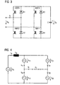
- FIG. 1 shows first the general structure of the converter in a version as a full bridge circuit.
- the mains voltage u N on At the input of the power converter is the mains voltage u N on.
- four power converter branches 11, 12, 21 and 22 are arranged.
- At the bridge diagonal is a medium-frequency transformer T with the primary voltage u T and the secondary voltage u T '.
- the power converter branches 11, 12, 21, 22 each consist of several submodules with the terminal voltage u x1 ... u xn .
- the submodule has the form of a full bridge circuit of a voltage converter, except that this is used here as a single two-terminal.
- the bridge circuit consists of four power semiconductor switches IGBT1 ... IGBT4 with antiparallel connected diodes D1 ... D4.
- a capacitor C is connected, which is charged to the voltage U d .
- the capacitors C of all submodules have a same output state with the capacitor voltage U d and in the Figures 1 and 2 a number n of submodules per power converter branch 11, 12, 21, 22 is present, the voltage u 11 , u 12 , u 21 , u 22 of a power converter branch 11, 12, 21, 22 the value range -n U d ... + nU d and can thus be placed in discrete "stairs" of the voltage U d .
- the fundamental frequency of the transformer transformer voltage u T and transformer current i T is significantly greater as those of the grid sizes mains voltage u N and mains current.
- the ratio of the fundamental frequencies of transformer sizes and network sizes is preferably integer.
- FIG. 4 is a fundamental equivalent circuit of the inverter according to FIG. 1 shown. This is based on a mains frequency of 16 2/3 Hz, ie a period of 60 ms, and a transformer frequency of 300 Hz. The power of the single-phase network pulsating at twice the mains frequency is buffered in the capacitors C of the submodules. Thus, an independent of the mains frequency power flow through the transformer T is possible.
- FIG. 5 shows the time course of the mains voltage u N and the mains current i N
- FIG. 6 the temporal course of the network power p N and the energy pulsating at twice the mains frequency.
- the control is performed so that the fundamental effective values of mains voltage u N (nominal value) and transformer primary voltage u T are about the same size.
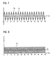
- Exemplary Time Losses of the Basic Voltages of Transformer Primary Voltage u T and Primary Current i T shows FIG. 7 .
- the control of the secondary-side power converter or is carried out so that the fundamental oscillations of current and voltage on the primary side are in phase.
- the time profiles of the transformer power p T and the transformer power averaged over a period of the transformer fundamental oscillation p T are in FIG. 8 shown.
- the power converter branches 11, 12, 21, 22 can be regarded as impressed voltage sources, wherein the submodules are controlled in accordance with the previous method, resulting in the following fundamental vibration voltages for the power converter branches 11, 12, 21, 22:
- FIG. 4 shows the fundamental equivalent circuit.
- u N is the fundamental of the mains voltage and u T is the fundamental of the transformer primary voltage.
- i N is the fundamental frequency of the mains current
- i T is the fundamental frequency of the transformer primary current
- the branch power p 11 u 11 * i 11 and the pulsating portion of the associated energy shows FIG. 10 ,
- Each of the four power converter branches 11, 12, 21, 22 must be designed to be the sum of half the mains voltage amplitude (including the tolerances of the network voltage u N ) and half the transformer voltage amplitude, which is at the rated value, in terms of the number of submodules the mains voltage amplitude oriented, can muster.
- An inverter phase (series connection of two power converter branches 11, 12 or 21, 22) is voltage-wise thus approximately to twice the mains voltage amplitude to dimension, although on her only the mains voltage amplitude must drop. It must therefore be significantly oversized, which manifests itself in a large number of submodules.
- the current amplitude of the output voltage at the bridge diagonal which corresponds to the transformer primary voltage u T , to a value in the range up to the maximum possible voltage amplitude, the current sum of the voltages of the capacitors C submodules and the current value of the mains voltage u N dependent is controlled.
- Exemplary time profiles of the fundamental oscillations of transformer primary voltage u T and transformer primary current i T shows FIG. 11 , Again, the control can be done as shown so that the fundamental oscillations of current and voltage on the primary side are in phase.
- the control of the secondary or the secondary converter is such that the in figure 12 setting shown power flow. This can be achieved by appropriate phase shift between the primary and secondary voltage at the transformer T.
- the individual power converter branches 11, 12, 21, 22 can also be regarded as impressed voltage sources in the inventive driving method, the submodules being controlled such that the following fundamental voltage voltages result for the power converter branches 11, 12, 21, 22:
- the control can be appropriately carried out again so that the fundamental of mains voltage u N and mains current i N have the same phase position.
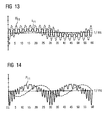
- the time profiles of branch voltage u 11 and branch current i 11 are in FIG. 13 shown. There, the uniform utilization in terms of current and voltage can be seen.
- the branch power p 11 u 11 * i 11 and the pulsating portion of the associated energy shows FIG. 14 , Visible is the opposite of the in FIG. 10 example increased by about a factor of 2, with double mains frequency pulsating energy.
- FIGS. 15 and 16 show a comparison of the previous with the inventive control with respect to the sum of the capacitor voltages u d ⁇ and u d ⁇ ' the submodules of a power converter branch 11, 12, 21, 22.
- For the transformer primary voltage u T is the difference of half the mains voltage u N / 2 and the sum the capacitor voltages u d ⁇ of the submodules of the Branch usable. Will the capacitor voltages u d , as FIG.
- control method By the control method according to the invention, the cost of control, power supply and high voltage insulation can be significantly reduced by reducing the number of submodules.
Landscapes
- Engineering & Computer Science (AREA)
- Power Engineering (AREA)
- Ac-Ac Conversion (AREA)
- Inverter Devices (AREA)
- Power Conversion In General (AREA)
- Control Of Motors That Do Not Use Commutators (AREA)
- Dc-Dc Converters (AREA)
Claims (3)
- Procédé de commande d'un convertisseur, qui est sous la forme d'un circuit en pont biphasé ou triphasé ayant un transformateur (T ) et ayant des branches de pont qui sont constituées d'un nombre quelconque de sous-modules identiques, la puissance du secteur étant emmagasinée intermédiairement dans des condensateurs (C ) des sous-modules, caractérisé en ce que la tension primaire du transformateur est formée de la tension (UN ) du secteur et des tensions sur les condensateurs (C ) de sorte que la tension primaire est diminuée lors du maximum dans le temps de la tension du secteur et est augmentée lors du passage par zéro dans le temps de la tension du secteur par charge et décharge des condensateurs (C ).
- Procédé de commande suivant la revendication 1, caractérisé en ce que les amplitudes de courant dans les diverses branches (11, 12, 21, 22) du convertisseur sont commandées de manière à être à peu près égales dans le temps.
- Procédé de commande suivant l'une des revendications précédentes, caractérisé en ce qu'au circuit en pont, la tension de sortie des diagonales du pont est appliquée sur un transformateur (T ) de fréquence médian, dont l'enroulement ou les enroulements secondaires sont reliés à au moins un convertisseur de tension.
Applications Claiming Priority (2)
| Application Number | Priority Date | Filing Date | Title |
|---|---|---|---|
| DE10323009 | 2003-05-21 | ||
| DE10323009A DE10323009A1 (de) | 2003-05-21 | 2003-05-21 | Steuerverfahren für einen Stromrichter |
Publications (3)
| Publication Number | Publication Date |
|---|---|
| EP1480322A2 EP1480322A2 (fr) | 2004-11-24 |
| EP1480322A3 EP1480322A3 (fr) | 2006-06-07 |
| EP1480322B1 true EP1480322B1 (fr) | 2008-07-02 |
Family
ID=33039250
Family Applications (1)
| Application Number | Title | Priority Date | Filing Date |
|---|---|---|---|
| EP04008990A Expired - Lifetime EP1480322B1 (fr) | 2003-05-21 | 2004-04-15 | Procédé de control d'un convertisseur de puissance |
Country Status (3)
| Country | Link |
|---|---|
| EP (1) | EP1480322B1 (fr) |
| AT (1) | ATE400079T1 (fr) |
| DE (2) | DE10323009A1 (fr) |
Families Citing this family (1)
| Publication number | Priority date | Publication date | Assignee | Title |
|---|---|---|---|---|
| CN107696873B (zh) * | 2017-10-23 | 2023-12-22 | 西南交通大学 | 一种动车组牵引传动供电系统 |
Family Cites Families (1)
| Publication number | Priority date | Publication date | Assignee | Title |
|---|---|---|---|---|
| GB2294821A (en) * | 1994-11-04 | 1996-05-08 | Gec Alsthom Ltd | Multilevel converter |
-
2003
- 2003-05-21 DE DE10323009A patent/DE10323009A1/de not_active Withdrawn
-
2004
- 2004-04-15 AT AT04008990T patent/ATE400079T1/de active
- 2004-04-15 EP EP04008990A patent/EP1480322B1/fr not_active Expired - Lifetime
- 2004-04-15 DE DE502004007472T patent/DE502004007472D1/de not_active Expired - Lifetime
Also Published As
| Publication number | Publication date |
|---|---|
| EP1480322A3 (fr) | 2006-06-07 |
| EP1480322A2 (fr) | 2004-11-24 |
| DE10323009A1 (de) | 2004-12-16 |
| ATE400079T1 (de) | 2008-07-15 |
| DE502004007472D1 (de) | 2008-08-14 |
Similar Documents
| Publication | Publication Date | Title |
|---|---|---|
| EP1311058B1 (fr) | Convertisseur de frequence | |
| DE102008014898B4 (de) | Verfahren zur Steuerung eines mehrphasigen Stromrichters mit verteilten Energiespeichern bei niedrigen Ausgangsfrequenzen | |
| EP2537239A2 (fr) | Onduleur à découpage à 3 étages avec réseau de délestage | |
| DE19750041C1 (de) | Halbleitersteller zur Erzeugung einer konstanten Ausgleichspannung U¶a¶ ohne Eingangsstromverzerrung bei variabler oder gleichgerichteter Eingangsgleichspannung U¶e¶ | |
| EP2586646B1 (fr) | Dispositif électrique d'alimentation en énergie pour dispositifs d'entraînement destiné au fonctionnement d'un véhicule sur rail sur des réseaux d'alimentation électriques | |
| EP2067227B1 (fr) | Alimentation en énergie motrice pour véhicules ferroviaires | |
| EP2421135B1 (fr) | Onduleur sans transformateur avec convertisseur abaisseur | |
| EP2592745A1 (fr) | Convertisseur électrique | |
| WO1997013309A1 (fr) | Transformateur oblique de puissance elevee, compatible avec le reseau, pilote par convertisseur de courant et appliquant une tension | |
| EP0952030B1 (fr) | Circuit électrique d'alimentation pour un système d'entraînement électrique | |
| EP0373381B1 (fr) | Procédé de commande d'un onduleur triphasé | |
| EP4378061A1 (fr) | Circuit convertisseur permettant de générer une tension continue isolée | |
| EP2786477B1 (fr) | Procédé de modulation d'un convertisseur continu-continu à résonance série d'une alimentation multi-niveaux moyenne fréquence d'un convertisseur de traction | |
| EP0534242B1 (fr) | Méthode pour la réduction des oscillations de tension au point neutre d'un onduleur à trois niveaux | |
| EP1480322B1 (fr) | Procédé de control d'un convertisseur de puissance | |
| EP3531547B1 (fr) | Circuit de commande permettant de coupler une machine synchrone avec un réseau de tension et procédé de fonctionnement dudit circuit | |
| EP3656032B1 (fr) | Dispositif compensateur série | |
| EP0534285B1 (fr) | Circuit de filtrage | |
| DE10323503A1 (de) | Stromrichter | |
| EP0015462B1 (fr) | Dispositif d'alimentation d'appareils de consommation d'énergie électrique sur un véhicule ferroviaire | |
| EP1870996A1 (fr) | Circuit pour alimenter d'énergie electrique dans un reseau de distribution électrique | |
| DE10323218A1 (de) | Hochspannungsumrichter und Verfahren zu seiner Ansteuerung | |
| DE10138751A1 (de) | Wechselrichter mit schnellschaltenden ansteuerbaren elektronischen Schaltern, insbesondere IGBT-Schaltern, sowie Verfahren zur Ansteuerung eines derartigen Wechselrichters | |
| AT402133B (de) | Steuereinrichtung für die energieversorgung eines verbraucherkreises eines gleichstromverbrauchers und ein verfahren zum betrieb einer derartigen steuereinrichtung | |
| EP4518136A1 (fr) | Convertisseur cc-cc résonant et procédé de fonctionnement d'un convertisseur cc-cc résonant |
Legal Events
| Date | Code | Title | Description |
|---|---|---|---|
| PUAI | Public reference made under article 153(3) epc to a published international application that has entered the european phase |
Free format text: ORIGINAL CODE: 0009012 |
|
| AK | Designated contracting states |
Kind code of ref document: A2 Designated state(s): AT BE BG CH CY CZ DE DK EE ES FI FR GB GR HU IE IT LI LU MC NL PL PT RO SE SI SK TR |
|
| AX | Request for extension of the european patent |
Extension state: AL HR LT LV MK |
|
| PUAL | Search report despatched |
Free format text: ORIGINAL CODE: 0009013 |
|
| AK | Designated contracting states |
Kind code of ref document: A3 Designated state(s): AT BE BG CH CY CZ DE DK EE ES FI FR GB GR HU IE IT LI LU MC NL PL PT RO SE SI SK TR |
|
| AX | Request for extension of the european patent |
Extension state: AL HR LT LV MK |
|
| RIC1 | Information provided on ipc code assigned before grant |
Ipc: H02M 5/297 20060101AFI20060425BHEP Ipc: H02M 5/27 20060101ALI20060425BHEP |
|
| 17P | Request for examination filed |
Effective date: 20061207 |
|
| AKX | Designation fees paid |
Designated state(s): AT CH DE FR IT LI SE |
|
| 17Q | First examination report despatched |
Effective date: 20070125 |
|
| GRAP | Despatch of communication of intention to grant a patent |
Free format text: ORIGINAL CODE: EPIDOSNIGR1 |
|
| GRAS | Grant fee paid |
Free format text: ORIGINAL CODE: EPIDOSNIGR3 |
|
| GRAA | (expected) grant |
Free format text: ORIGINAL CODE: 0009210 |
|
| AK | Designated contracting states |
Kind code of ref document: B1 Designated state(s): AT CH DE FR IT LI SE |
|
| REG | Reference to a national code |
Ref country code: CH Ref legal event code: NV Representative=s name: SIEMENS SCHWEIZ AG Ref country code: CH Ref legal event code: EP |
|
| REF | Corresponds to: |
Ref document number: 502004007472 Country of ref document: DE Date of ref document: 20080814 Kind code of ref document: P |
|
| REG | Reference to a national code |
Ref country code: SE Ref legal event code: TRGR |
|
| REG | Reference to a national code |
Ref country code: CH Ref legal event code: PCAR Free format text: SIEMENS SCHWEIZ AG;INTELLECTUAL PROPERTY FREILAGERSTRASSE 40;8047 ZUERICH (CH) |
|
| PLBE | No opposition filed within time limit |
Free format text: ORIGINAL CODE: 0009261 |
|
| STAA | Information on the status of an ep patent application or granted ep patent |
Free format text: STATUS: NO OPPOSITION FILED WITHIN TIME LIMIT |
|
| 26N | No opposition filed |
Effective date: 20090403 |
|
| PGFP | Annual fee paid to national office [announced via postgrant information from national office to epo] |
Ref country code: FR Payment date: 20110427 Year of fee payment: 8 Ref country code: SE Payment date: 20110412 Year of fee payment: 8 |
|
| PGFP | Annual fee paid to national office [announced via postgrant information from national office to epo] |
Ref country code: AT Payment date: 20110309 Year of fee payment: 8 |
|
| PGFP | Annual fee paid to national office [announced via postgrant information from national office to epo] |
Ref country code: IT Payment date: 20110421 Year of fee payment: 8 |
|
| PGFP | Annual fee paid to national office [announced via postgrant information from national office to epo] |
Ref country code: CH Payment date: 20110711 Year of fee payment: 8 |
|
| PGFP | Annual fee paid to national office [announced via postgrant information from national office to epo] |
Ref country code: DE Payment date: 20110620 Year of fee payment: 8 |
|
| REG | Reference to a national code |
Ref country code: CH Ref legal event code: PL |
|
| REG | Reference to a national code |
Ref country code: SE Ref legal event code: EUG |
|
| REG | Reference to a national code |
Ref country code: AT Ref legal event code: MM01 Ref document number: 400079 Country of ref document: AT Kind code of ref document: T Effective date: 20120415 |
|
| REG | Reference to a national code |
Ref country code: FR Ref legal event code: ST Effective date: 20121228 |
|
| PG25 | Lapsed in a contracting state [announced via postgrant information from national office to epo] |
Ref country code: CH Free format text: LAPSE BECAUSE OF NON-PAYMENT OF DUE FEES Effective date: 20120430 Ref country code: AT Free format text: LAPSE BECAUSE OF NON-PAYMENT OF DUE FEES Effective date: 20120415 Ref country code: LI Free format text: LAPSE BECAUSE OF NON-PAYMENT OF DUE FEES Effective date: 20120430 |
|
| REG | Reference to a national code |
Ref country code: DE Ref legal event code: R119 Ref document number: 502004007472 Country of ref document: DE Effective date: 20121101 |
|
| PG25 | Lapsed in a contracting state [announced via postgrant information from national office to epo] |
Ref country code: FR Free format text: LAPSE BECAUSE OF NON-PAYMENT OF DUE FEES Effective date: 20120430 Ref country code: IT Free format text: LAPSE BECAUSE OF NON-PAYMENT OF DUE FEES Effective date: 20120415 Ref country code: SE Free format text: LAPSE BECAUSE OF NON-PAYMENT OF DUE FEES Effective date: 20120416 |
|
| PG25 | Lapsed in a contracting state [announced via postgrant information from national office to epo] |
Ref country code: DE Free format text: LAPSE BECAUSE OF NON-PAYMENT OF DUE FEES Effective date: 20121101 |