EP1480565B1 - Vaskuläre okklusionsvorrichtung - Google Patents
Vaskuläre okklusionsvorrichtung Download PDFInfo
- Publication number
- EP1480565B1 EP1480565B1 EP03716279A EP03716279A EP1480565B1 EP 1480565 B1 EP1480565 B1 EP 1480565B1 EP 03716279 A EP03716279 A EP 03716279A EP 03716279 A EP03716279 A EP 03716279A EP 1480565 B1 EP1480565 B1 EP 1480565B1
- Authority
- EP
- European Patent Office
- Prior art keywords
- occlusion device
- disk
- central
- ribs
- members
- Prior art date
- Legal status (The legal status is an assumption and is not a legal conclusion. Google has not performed a legal analysis and makes no representation as to the accuracy of the status listed.)
- Expired - Lifetime
Links
- 206010053648 Vascular occlusion Diseases 0.000 title description 22
- 208000021331 vascular occlusion disease Diseases 0.000 title description 22
- 239000000463 material Substances 0.000 claims abstract description 30
- 229920000954 Polyglycolide Polymers 0.000 claims description 2
- 229920000747 poly(lactic acid) Polymers 0.000 claims description 2
- 229920002463 poly(p-dioxanone) polymer Polymers 0.000 claims description 2
- 229920001610 polycaprolactone Polymers 0.000 claims description 2
- 239000004632 polycaprolactone Substances 0.000 claims description 2
- 239000000622 polydioxanone Substances 0.000 claims description 2
- 239000004633 polyglycolic acid Substances 0.000 claims description 2
- 239000004626 polylactic acid Substances 0.000 claims description 2
- 230000007547 defect Effects 0.000 description 19
- 239000012528 membrane Substances 0.000 description 11
- 210000001367 artery Anatomy 0.000 description 8
- 238000000034 method Methods 0.000 description 8
- 208000025339 heart septal defect Diseases 0.000 description 5
- 229920000642 polymer Polymers 0.000 description 5
- 238000001361 intraarterial administration Methods 0.000 description 4
- 238000007789 sealing Methods 0.000 description 4
- 208000013914 atrial heart septal defect Diseases 0.000 description 3
- 230000003628 erosive effect Effects 0.000 description 3
- 229920003023 plastic Polymers 0.000 description 3
- 239000004033 plastic Substances 0.000 description 3
- 208000035478 Interatrial communication Diseases 0.000 description 2
- 208000001910 Ventricular Heart Septal Defects Diseases 0.000 description 2
- 210000000709 aorta Anatomy 0.000 description 2
- 230000000712 assembly Effects 0.000 description 2
- 238000000429 assembly Methods 0.000 description 2
- 206010003664 atrial septal defect Diseases 0.000 description 2
- 239000008280 blood Substances 0.000 description 2
- 210000004369 blood Anatomy 0.000 description 2
- 239000007943 implant Substances 0.000 description 2
- 229920002635 polyurethane Polymers 0.000 description 2
- 239000004814 polyurethane Substances 0.000 description 2
- 229920002379 silicone rubber Polymers 0.000 description 2
- 230000002792 vascular Effects 0.000 description 2
- 210000003462 vein Anatomy 0.000 description 2
- 206010002329 Aneurysm Diseases 0.000 description 1
- 208000032170 Congenital Abnormalities Diseases 0.000 description 1
- 238000002679 ablation Methods 0.000 description 1
- 230000003466 anti-cipated effect Effects 0.000 description 1
- 230000010100 anticoagulation Effects 0.000 description 1
- 230000001746 atrial effect Effects 0.000 description 1
- 238000010009 beating Methods 0.000 description 1
- 239000004621 biodegradable polymer Substances 0.000 description 1
- 230000015572 biosynthetic process Effects 0.000 description 1
- 230000000740 bleeding effect Effects 0.000 description 1
- 210000004204 blood vessel Anatomy 0.000 description 1
- 230000000747 cardiac effect Effects 0.000 description 1
- 238000004891 communication Methods 0.000 description 1
- 208000028831 congenital heart disease Diseases 0.000 description 1
- 230000007797 corrosion Effects 0.000 description 1
- 238000005260 corrosion Methods 0.000 description 1
- 230000003247 decreasing effect Effects 0.000 description 1
- 238000013461 design Methods 0.000 description 1
- 230000000694 effects Effects 0.000 description 1
- 239000004744 fabric Substances 0.000 description 1
- 210000001105 femoral artery Anatomy 0.000 description 1
- 239000006260 foam Substances 0.000 description 1
- 239000003102 growth factor Substances 0.000 description 1
- 230000023597 hemostasis Effects 0.000 description 1
- 230000002439 hemostatic effect Effects 0.000 description 1
- 210000003090 iliac artery Anatomy 0.000 description 1
- 238000003384 imaging method Methods 0.000 description 1
- 238000002347 injection Methods 0.000 description 1
- 239000007924 injection Substances 0.000 description 1
- 238000003780 insertion Methods 0.000 description 1
- 230000037431 insertion Effects 0.000 description 1
- 230000003601 intercostal effect Effects 0.000 description 1
- 230000007774 longterm Effects 0.000 description 1
- 210000004072 lung Anatomy 0.000 description 1
- 238000013507 mapping Methods 0.000 description 1
- 239000002184 metal Substances 0.000 description 1
- 239000007769 metal material Substances 0.000 description 1
- 239000003226 mitogen Substances 0.000 description 1
- 230000003387 muscular Effects 0.000 description 1
- 208000003278 patent ductus arteriosus Diseases 0.000 description 1
- 230000035515 penetration Effects 0.000 description 1
- 230000002035 prolonged effect Effects 0.000 description 1
- 210000001147 pulmonary artery Anatomy 0.000 description 1
- 238000001356 surgical procedure Methods 0.000 description 1
- 230000001225 therapeutic effect Effects 0.000 description 1
- 230000008467 tissue growth Effects 0.000 description 1
- 201000003130 ventricular septal defect Diseases 0.000 description 1
Images








Classifications
-
- A—HUMAN NECESSITIES
- A61—MEDICAL OR VETERINARY SCIENCE; HYGIENE
- A61B—DIAGNOSIS; SURGERY; IDENTIFICATION
- A61B17/00—Surgical instruments, devices or methods
- A61B17/0057—Implements for plugging an opening in the wall of a hollow or tubular organ, e.g. for sealing a vessel puncture or closing a cardiac septal defect
-
- A—HUMAN NECESSITIES
- A61—MEDICAL OR VETERINARY SCIENCE; HYGIENE
- A61B—DIAGNOSIS; SURGERY; IDENTIFICATION
- A61B17/00—Surgical instruments, devices or methods
- A61B2017/00004—(bio)absorbable, (bio)resorbable or resorptive
-
- A—HUMAN NECESSITIES
- A61—MEDICAL OR VETERINARY SCIENCE; HYGIENE
- A61B—DIAGNOSIS; SURGERY; IDENTIFICATION
- A61B17/00—Surgical instruments, devices or methods
- A61B17/00234—Surgical instruments, devices or methods for minimally invasive surgery
- A61B2017/00238—Type of minimally invasive operation
- A61B2017/00243—Type of minimally invasive operation cardiac
-
- A—HUMAN NECESSITIES
- A61—MEDICAL OR VETERINARY SCIENCE; HYGIENE
- A61B—DIAGNOSIS; SURGERY; IDENTIFICATION
- A61B17/00—Surgical instruments, devices or methods
- A61B17/0057—Implements for plugging an opening in the wall of a hollow or tubular organ, e.g. for sealing a vessel puncture or closing a cardiac septal defect
- A61B2017/00575—Implements for plugging an opening in the wall of a hollow or tubular organ, e.g. for sealing a vessel puncture or closing a cardiac septal defect for closure at remote site, e.g. closing atrial septum defects
-
- A—HUMAN NECESSITIES
- A61—MEDICAL OR VETERINARY SCIENCE; HYGIENE
- A61B—DIAGNOSIS; SURGERY; IDENTIFICATION
- A61B17/00—Surgical instruments, devices or methods
- A61B17/0057—Implements for plugging an opening in the wall of a hollow or tubular organ, e.g. for sealing a vessel puncture or closing a cardiac septal defect
- A61B2017/00575—Implements for plugging an opening in the wall of a hollow or tubular organ, e.g. for sealing a vessel puncture or closing a cardiac septal defect for closure at remote site, e.g. closing atrial septum defects
- A61B2017/00592—Elastic or resilient implements
-
- A—HUMAN NECESSITIES
- A61—MEDICAL OR VETERINARY SCIENCE; HYGIENE
- A61B—DIAGNOSIS; SURGERY; IDENTIFICATION
- A61B17/00—Surgical instruments, devices or methods
- A61B17/0057—Implements for plugging an opening in the wall of a hollow or tubular organ, e.g. for sealing a vessel puncture or closing a cardiac septal defect
- A61B2017/00575—Implements for plugging an opening in the wall of a hollow or tubular organ, e.g. for sealing a vessel puncture or closing a cardiac septal defect for closure at remote site, e.g. closing atrial septum defects
- A61B2017/00597—Implements comprising a membrane
-
- A—HUMAN NECESSITIES
- A61—MEDICAL OR VETERINARY SCIENCE; HYGIENE
- A61B—DIAGNOSIS; SURGERY; IDENTIFICATION
- A61B17/00—Surgical instruments, devices or methods
- A61B17/0057—Implements for plugging an opening in the wall of a hollow or tubular organ, e.g. for sealing a vessel puncture or closing a cardiac septal defect
- A61B2017/00575—Implements for plugging an opening in the wall of a hollow or tubular organ, e.g. for sealing a vessel puncture or closing a cardiac septal defect for closure at remote site, e.g. closing atrial septum defects
- A61B2017/00606—Implements H-shaped in cross-section, i.e. with occluders on both sides of the opening
Definitions
- This invention relates to the field of medical devices, and more specifically to an apparatus for vascular occlusion.
- Vascular occlusion devices such as atrial septal defect closure devices are used for closing defects or holes in the vascular system of a body.
- Such devices usually include an occluding member which is dimensioned larger than the hole, and some technique for mounting the occluding member to the tissue proximate the defect or hole.
- U.S. Patent No. 6,312,446 B1 (Buscemi Paul J. et al. ) discloses a catheter delivered device to close a septal defect, the device comprising a cylindrical shaft of metal or polymeric material with concentric parallel cuts through the wall of the device which create flattened support struts.
- the center of the support struts move radially away from the axis in a hinge like fashion in response to the movement of the device's proximal and distal ends toward the center of the device. This movement is reversibly effected through mechanical means.
- the device can be coated with growth factors, mitogenic factors or other determinants which can improve tissue growth such that tissue ingrowth can occur over a period of time.
- the catheter itself may be an ultrasonic imaging catheter.
- WO 96/32882 A discloses devices, systems, and methods for accessing the interior of the heart, and performing procedures therein while the heart is beating.
- a tubular access device is positioned through an intercostal space and through a muscular wall of the heart.
- the access device includes a balloon or flange for sealing the penetration to prevent leakage of blood.
- An obturator is positionable in the access device, and includes cutting means located at its distal end. Elongated instruments are introduced through the access device to perform surgical procedures including septal device repair, ablation, and electrophysiological mapping.
- U.S. Patent No. 5,904,703 discloses a transcatheter occluder device for closing an opening in a tissue wall that includes a body member formed of an open cell polymer foam capable of holding a predetermined occluder shape and being resiliently compressible for transcatheter deployment.
- the occluder device includes a pair of spaced-apart disks interconnected by a narrow neck portion. Grip means are provided in the neck portion to releasably engage a guide wire for deployment of the occluder device through a catheter.
- WO 01/17435 A discloses a septal defect closure device having a first occluding disk having a first flexible membrane attached to a first frame and a second occluding disk having a second flexible membrane attached to a separate second frame.
- the first frame has at least two outwardly extending loops joined to one another by flexible joints. These loops are attached to the first membrane to define taut fabric petals when the first disk is in a deployed configuration.
- a central portion of the first membrane is joined to the central portion of the second membrane via a joining segment, which may comprise a conjoint disk.
- the flexible joints of the first frame are received within the joining segment.
- GB Patent No. 2,269,321 A discloses an occluder device for a body duct that comprises first and second expansion assemblies connected to each other and provided with attachment means for connection to a wire and catheter positioning system, each assembly comprising a web of material and at least three resilient arms projecting, when undeformed, radially from the device and carrying the web, the arms being resiliently biased apart to open up and resiliently deformable to close down the associated web in an umbrella-like manner.
- the assemblies are joined at their central portions and arranged oppositely to each other.
- Each arm is bent through an angle such that, when the webs are opened up, the distal ends of the arms of each web point generally towards the other web and the two webs are biased into contact with one another at their peripheries.
- U.S. Patent No. 5,350,399 (Erlenbacher et al. ) recites that the sealing device is composed of an intra-arterial occluder and an extra-arterial occluder, both made of resilient biocompatible and/or bioabsorbable material and held in place via a saw-toothed guide extending integrally from the intra-arterial occluder.
- An insertion tool is provided to effect sliding of the extra-arterial occluder over the guide and fixation of the extra-arterial occluder to the guide in sealed relation over an opening in body tissue and safe cutting of the guide.
- a force gauge is provided on the tool to indicate the sealing pressure on the intra-arterial occluder.
- U.S. Patent No. 5,342,393 (Stack Richard ) recites that a method and device are provided for sealing a perforation in the wall of, for example, a blood vessel.
- the device is in the form of a two part closure which seals the hole by clamping the tissue surrounding the hole from both the inside and the outside of the vessel.
- two rivet portions are provided which are bayonet or screw threadedly interlocked to clamp the vessel wall about the perforation.
- An alternate embodiment applies heat to couple the rivet parts as well as to cauterize the wound site. Heat may also advantageously be used to separate the rivet from its delivery system.
- U.S. Patent No. 5,827,325 recites an implant, in particular for the closure of trocar puncture points, that has a flexible, flat base part and a stopper part that starts from one side of the base part and extends in an essentially perpendicular manner relative to the base part.
- the stopper part can be provided with a waist in the vicinity of the base part.
- the devices are typically made of a wire frame or skeleton which can become fatigued or perforate the tissue wall. It is also desirable to center the device within the hole and provide a stable technique for keeping the device securely mounted to the tissue.
- the present system provides a device that can be used to occlude defects in the vascular system by minimally invasive means.
- Patients are often born with congenital defects in the heart commonly alluded to as “holes in the heart.” This may be between the upper chambers in the heart called “atrial septal defects” or between the lower chambers of the heart called” ventricular septal defects. "In other instances, it may be "patent ductus arteriosii” when it is a communication between the aorta and pulmonary artery.
- arteriovenous fistulae at several sites within the body, or the presence of collateral arteries to the lungs that bring excessive amounts of blood and require closure.
- the present system includes a vascular occlusion device that can be self-centering, can completely occlude defects, and can also be retrieved back into the delivery catheter in case of sub-optimal deployments.
- a vascular occlusion device can include no metallic components.
- the device can be made from bio-compatible plastic materials that permit it to be injection molded, vacuum formed, or extruded.
- the device is made from a bio-adsorbable polymer or a bio-degradable polymer. After deployment of the device, such a polymer is gradually replaced by fibrous tissue and resorbed over a period of months. No metallic components remain and this permits the most desirable form of repair of such defects. In other instances, where a bio-adsorbable material is not appropriate, for fear of aneurysm formation in high pressure shunts, silicone elastomers, polyurethanes or combinations of the two can be used.
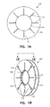
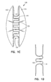
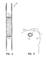
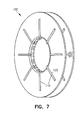
- Figure 1A-7 show a vascular occlusion device 100 according to one embodiment.
- Device 100 includes a double disk device, with two flanges 102 and 104 that extend outwards from a central area 106.
- the central area 106 is dimensioned to act as a self-centering mechanism to allow the flanges and the device to be substantially centered over the defect.
- the central area occludes the defect and extends to the double flanges circumferentially.
- central area 106 has a diameter of approximately 12 mm, with the flanges 102 and 104 having a diameter of approximately 30 mm.
- Device 100 includes a self-expanding skeleton structure 110 that provides the major structural strength of the device.
- Skeleton structure 110 includes a plurality of ribs 125. Between each of the ribs 125 are thinner membrane portions 127. In one example, the membrane portions 127 can be approximately 0,254 mm (0.01 inches) thick, or less. Ribs 125 can be approximately 0,635 mm (0.025 inches) thick.
- Skeleton 110 supports a main body structure which includes the flanges 102 and 104. As seen in Figures 1C, 1D , 3 , 4, 5 , 6 and 7 , the skeleton has a sinuous structure around the central rim 120 that permits the rim area to be collapsed down.
- ribs 125 extend radially along each disk.
- holes 130 are incorporated whose function is to be the sites to tether it to the release mechanism (see Figure 5 ) with a tether 139.
- holes 130 are located at the ends of ribs 125 with a section of rib encircling the hole.
- Device 100 is flexible, compressible, and self-expandable and can be used in a manner known in the art.
- the device 100 can be collapsed into a catheter by folding the flanges 102 and 104 outwards and collapsing the central rim 120.
- the catheter is then passed through an atrial or ventricular septal defect, or other hole in a body.
- the first disk 102 of device 100 is pushed out of the catheter and springably opens on one side of the defect.
- the rib configuration of the skeleton structure of each flange automatically expands the flange to its original dimensions on release from the confines of the catheter.
- the expanded disk 102 is then drawn back to the defect.
- the catheter is pulled back, and second disk 104 then springably opens on the second side of the defect.
- the central rim area 120 also expands to its original size and abuts the inner diameter surface of the defect. This acts as a centering mechanism to center the flanges of the device on each side of the defect.
- the outer surface of rim 120 diametrically extends from a first surface 121 to a second surface 123. These surfaces and the rest of the expanded rim surface are biased towards and can contact the inner surface of the defect to help center the device.
- tethers 139 which are attached at one or more of holes 130 can be used to retrieve the device.
- the device can be re-collapsed into the catheter.
- holes 130 are structurally connected to ribs 125.
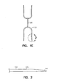
- Figure 2 shows one example of a distal end of a rib 125 of device 100.
- the end 141 of rib 125 is thinner (approximately 0,254 mm (0.01 inches)) than the inner portion 143 (approximately 0,635 mm (0.025 inches)) of the rib.
- Figure 2 shows one example of a distal end of a rib 125 of device 100.
- the end 141 of rib 125 is thinner (approximately 0,254 mm (0.01 inches)) than the inner portion 143 (approximately 0,635 mm (0.025 inches)) of the rib.
- the periphery area of each flange is a little more flexible and softer than the middle regions. This can help eliminate tissue erosion by the device once it is implanted.
- device 100 is molded from a non-metallic material. Such an occlusion device has better tolerance than prior devices and has better long-term stability. Possible materials include: silicone elastomers, polyurethanes, or combinations of the two, and other compatible materials.
- device 100 is a one-piece, completely integrated device formed of a single material with ribs 110 being thicker parts of the material. This allows for fast manufacturability since the device can be molded or otherwise formed in a single process.
- the ribs are formed of one type of material and the membrane portion from a different type of material.
- the device includes a bio-adsorbable material.
- bio-adsorbable material examples include: polyglycolic acid, polydioxanone, polylactic acid, and polycaprolactone, etc. Some embodiments use other bio-degradable and bioabsorbable plastics. Again, in some embodiments, these poly materials can be used to form the device as a single integrated unit formed of a single, moldable material. Using a bioabsorbable material as described above allows the device to slowly be resorbed into the body while the poly material is replaced by tissue. This results in a closed defect and leaves no metallic parts in a body.
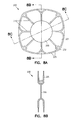
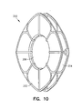
- Figures 8A-10 show a vascular occlusion device 200 according to one embodiment not forming part of the present invention.
- Device 200 includes a pair of disk members defining a pair of flange members 202 and 204 connected by a central area 206.
- the skeleton structure 210 of occlusion device 200 includes an appearance of the petals of a flower.
- the skeleton 210 of device 200 runs across from one side to the other through a central area 206.
- skeleton 210 includes rib portions 225 running towards and around the periphery of each flange of the device.
- Holes 230 are provided similar to holes 130 described above.
- the central area 206 can be dimensioned to provide a self-centering device by having an outer rim surface 220 to abut the defect. While the disk shape shown is square- shaped, it may be round, oval, rectangular, or any other desirable shape.
- the thickness of the skeleton is variable and is determined by the occlusive pressures that will force the device from the defect.
- the thickness of the membrane can be variable. In one example, the membrane portion can be about 0,254 mm (0.010 inches) or less, with the ribs being about 0,502 mm (0.020 inches) to 0,635 mm (0.025 inches).
- the membrane in both the flanges can be perforated, and sieve like, to reduce the bulk of the device, so that it can be more easily loaded into a catheter. It would be desirable for the central area to be free of perforations for the shunt to be occluded.
- the central area 206 is about 10 mm in diameter and each flange has a diameter of approximately 28 mm.
- Device 200 can be constructed of the same material as for device 100 and the above discussion is incorporated herein by reference.
- Figures 11A-11C show a device 300 for closure of patent ductus arteriosii (PDA), according to one embodiment not forming part of the present invention.
- Device 300 includes only one disk 302. There is a central tubular area 306 that is sized to fit into the patent ductus arteriosus.
- the circular ring 310 is for the release mechanism.
- Device 300 can be loaded into a catheter and this is used to cross the PDA.
- the circular disk 302 and the tubular section 306 are opened in the aorta and then it is pulled back into the PDA, so that the disk occludes the defect, and the tubular section seated in the PDA, keeps it in place and centered. If required, the device can be drawn back into the catheter for retrieval in case of sub-optimal deployment.
- Device 300 can be constructed of the same material as for device 100 and the above discussion is incorporated herein by reference.
- Device 300 can include ribs 320 extending outwardly along a face of the disk 302.
- device 300 can be formed as an integral, one-piece design.
- device 300 can be molded from a plastic material, such as a bioabsorbable material as discussed above.
- FIGS 12A-13D show a device 400 that can be used to occlude puncture sites in the fomoral artery or vein after percutaneous interventions, in accordance with one embodiment not forming part of the present invention.
- device 400 includes a bio-adsorbable polymer. It has an intra-vascular member 402 that is rectangular in shape or oval. This is connected by a wide "waist" 404 to the extra-vascular member 406, that leads to a ring 408.
- the waist is designed to be slightly larger than the puncture hole in the artery or vein. For instance, with 6, 8 or 10 French catheter systems, the hole in the vessel can be as large as 1.98, 2.64, or 3.3 mm.
- the occluder is designed in different sizes so that the waist between the intravascular and extravascular disks are 2,2. 75 or 3.5 mm in diameter. This allows the present device to fit into the hole and tightly occlude it.
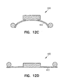
- Figures 12B-12D show the shape of intra-vascular member 402 according to one embodiment.
- member 402 has a rectangle shape of approximately 6 mm by 8 mm, and which is curved to form a partial cylindrical shape. This allows the member to sit flush against an inner surface along the axis of the artery (See Figure 13D ).
- the external disk 406 is structured to prevent device 400 from prolapsing back into the artery and producing a total occlusion of the artery.
- Device 400 can be constructed of the same material as for device 100 and the above discussion is incorporated herein by reference.
- Figures 13A-13D show one example of device 400 in use.
- an angiogram is obtained to identify the site of puncture, to ensure that it is above the bifurcation of the femoral artery.
- Device 400 is loaded into its sheath and this is passed through the previous sheath into the common iliac artery.
- the device is partially extruded until the intravascular disk 402 opens inside the artery.
- the whole unit is withdrawn, until the intravascular disk is snug against the artery.
- the device is held in place, using the release device 430, and the sheath 440 is drawn back so that the extravascular disk is opened.
- the sheaths are drawn back.
- the "self-centering" mechanism of the device permits the device to tightly occlude the defect.
- the intravascular disk prevents the device from being blown out by the intra-arterial pressure. Once hemostasis is confirmed, the device is released. It is anticipated that the bioabsorbable polymer would resorb over the course of a few weeks and heal with no foreign bodies remaining in the site.
- the material of a device can be modified as necessary to prolong or shorten the resorption period to allow for predictable resorption times.
Landscapes
- Health & Medical Sciences (AREA)
- Surgery (AREA)
- Life Sciences & Earth Sciences (AREA)
- Animal Behavior & Ethology (AREA)
- Public Health (AREA)
- Engineering & Computer Science (AREA)
- Biomedical Technology (AREA)
- Heart & Thoracic Surgery (AREA)
- Medical Informatics (AREA)
- Molecular Biology (AREA)
- Cardiology (AREA)
- General Health & Medical Sciences (AREA)
- Nuclear Medicine, Radiotherapy & Molecular Imaging (AREA)
- Veterinary Medicine (AREA)
- Surgical Instruments (AREA)
- Compounds Of Unknown Constitution (AREA)
- Medicines Containing Antibodies Or Antigens For Use As Internal Diagnostic Agents (AREA)
- Medicines That Contain Protein Lipid Enzymes And Other Medicines (AREA)
- Materials For Medical Uses (AREA)
- Media Introduction/Drainage Providing Device (AREA)
- Prostheses (AREA)
Claims (16)
- Verschlussvorrichtung (100, 200), aufweisend:ein erstes und ein zweites Scheibenelement (102, 104), wobei das erste und das zweite Scheibenelement (102, 104) jeweils einen selbst aufspreizenden, nicht metallischen Aufbau haben, der mehrere integrale Rippenelemente (125) aufweist, die biegsam sind, so dass sie innerhalb eines Katheters zusammengedrückt werden können, und die zu einer offenen Position zum Aufspreizen der Scheibenelemente (102, 104), wenn sie von dem Katheter entfernt werden, vorgespannt sind, undeinen zentralen Rand (120), der zusammenlegbar ist und mittels welchem das erste und das zweite Scheibenelement (102, 104) miteinander verbunden sind, und wobei die Verschlussvorrichtung (100) eine wellenförmige Struktur um den zentralen Rand (120) aufweist.
- Verschlussvorrichtung nach Anspruch 1, wobei die Verschlussvorrichtung (100, 200) ein bioabsorbierbares Material aufweist.
- Verschlussvorrichtung nach Anspruch 2, wobei das bioabsorbierbare Material Polyglykolsäure aufweist.
- Verschlussvorrichtung nach Anspruch 2, wobei das bioabsorbierbare Material Polydioxanon aufweist.
- Verschlussvorrichtung nach Anspruch 2, wobei das bioabsorbierbare Material Polymilchsäure aufweist.
- Verschlussvorrichtung nach Anspruch 2, wobei das bioabsorbierbare Material Polycaprolacton aufweist.
- Verschlussvorrichtung nach Anspruch 1, wobei das erste und das zweite Scheibenelement (102, 104) miteinander an einem zentralen Bereich (106) verbunden sind, der einen Umfang hat und wobei mehrere Rippen (125) um den Umfang des zentralen Bereichs (106) angeordnet sind.
- Verschlussvorrichtung nach Anspruch 1, wobei jede der mehreren Rippen (125) radial auf dem ersten und dem zweiten Scheibenelement (102, 104) ausgerichtet ist.
- Verschlussvorrichtung nach Anspruch 1, wobei mindestens ein Teil der mehreren Rippen (125) eine blütenblattförmige Konfiguration definiert.
- Verschlussvorrichtung nach Anspruch 1, wobei das erste und das zweite Scheibenelement (102, 104) zwischeneinander einen zentralen Bereich (106) haben, wobei der zentrale Bereich (106) bemessen ist, um sich über ein Loch in einem Gewebe zu erstrecken, wobei der zentrale Bereich (106) einen Außenumfang aufweist, der mehrere Rippen aufweist, um den Umfang gegen das Gewebe vorzuspannen.
- Verschlussvorrichtung nach Anspruch 1, die ferner ein oder mehrere Löcher (130) aufweist, die in einem der Scheibenelemente (102, 104) in der Nähe eines Umfangs des Scheibenelements ausgebildet ist/sind.
- Verschlussvorrichtung nach Anspruch 11, wobei das eine oder die mehreren Löcher von einem Teil der Rippenelemente (125) eingefasst ist.
- Verschlussvorrichtung nach Anspruch 1, wobei eines oder mehrere Rippenelemente (125) zu einem Außenende des Rippenelements dünner ausgebildet sind.
- Verschlussvorrichtung nach Anspruch 1, wobei die Verschlussvorrichtung (100, 200) eine einstückige Vorrichtung ist.
- Verschlussvorrichtung nach Anspruch 1, wobei die Vorrichtung eine einzige integrierte Formeinheit aufweist, die das erste und das zweite Scheibenelement, die Rippen und eine zentrierende Zentralscheibe aufweist.
- Verschlussvorrichtung nach Anspruch 1, wobei die Vorrichtung eine einzige integrierte geformte Einheit aufweist, die aus einem bioabsorbierbaren Material gebildet ist, die das erste und das zweite Scheibenelement, die Rippen und eine zentrierende Zentralscheibe aufweist, wobei die Zentralscheibe zusammendrückbar und bemessen ist, um sich bei ihrem Aufspreizen über ein Loch in einem Gewebe zu erstrecken.
Applications Claiming Priority (3)
| Application Number | Priority Date | Filing Date | Title |
|---|---|---|---|
| US36112202P | 2002-03-01 | 2002-03-01 | |
| US361122P | 2002-03-01 | ||
| PCT/US2003/006473 WO2003073944A1 (en) | 2002-03-01 | 2003-03-03 | Vascular occlusion device |
Publications (3)
| Publication Number | Publication Date |
|---|---|
| EP1480565A1 EP1480565A1 (de) | 2004-12-01 |
| EP1480565B1 true EP1480565B1 (de) | 2008-12-10 |
| EP1480565B8 EP1480565B8 (de) | 2009-04-01 |
Family
ID=27789072
Family Applications (1)
| Application Number | Title | Priority Date | Filing Date |
|---|---|---|---|
| EP03716279A Expired - Lifetime EP1480565B8 (de) | 2002-03-01 | 2003-03-03 | Vaskuläre okklusionsvorrichtung |
Country Status (8)
| Country | Link |
|---|---|
| EP (1) | EP1480565B8 (de) |
| JP (1) | JP4373221B2 (de) |
| AT (1) | ATE416676T1 (de) |
| AU (1) | AU2003219991A1 (de) |
| CA (1) | CA2477833C (de) |
| DE (1) | DE60325175D1 (de) |
| ES (1) | ES2319273T3 (de) |
| WO (1) | WO2003073944A1 (de) |
Cited By (6)
| Publication number | Priority date | Publication date | Assignee | Title |
|---|---|---|---|---|
| US10806458B2 (en) | 2014-05-02 | 2020-10-20 | W. L. Gore & Associates, Inc. | Anastomosis devices |
| US10980663B2 (en) | 2011-03-08 | 2021-04-20 | W. L. Gore & Associates, Inc. | Medical device for use with a stoma |
| WO2023101921A1 (en) * | 2021-12-03 | 2023-06-08 | Edwards Lifesciences Corporation | Surgical pad reinforcement |
| US11712230B2 (en) | 2014-05-02 | 2023-08-01 | W. L. Gore & Associates, Inc. | Occluder and anastomosis devices |
| US11724075B2 (en) | 2017-04-18 | 2023-08-15 | W. L. Gore & Associates, Inc. | Deployment constraining sheath that enables staged deployment by device section |
| US12303132B2 (en) | 2014-05-02 | 2025-05-20 | W. L. Gore & Associates, Inc. | Occluder and anastomosis devices |
Families Citing this family (20)
| Publication number | Priority date | Publication date | Assignee | Title |
|---|---|---|---|---|
| EP1509144A4 (de) | 2002-06-03 | 2008-09-03 | Nmt Medical Inc | Vorrichtung mit einem biologischen gewebegerüst für den intrakardialen defektverschluss |
| US7192435B2 (en) * | 2003-09-18 | 2007-03-20 | Cardia, Inc. | Self centering closure device for septal occlusion |
| US20050113868A1 (en) * | 2003-11-20 | 2005-05-26 | Devellian Carol A. | Device, with electrospun fabric, for a percutaneous transluminal procedure, and methods thereof |
| US9259267B2 (en) | 2005-09-06 | 2016-02-16 | W.L. Gore & Associates, Inc. | Devices and methods for treating cardiac tissue |
| US7797056B2 (en) | 2005-09-06 | 2010-09-14 | Nmt Medical, Inc. | Removable intracardiac RF device |
| US9232997B2 (en) | 2006-11-07 | 2016-01-12 | Corvia Medical, Inc. | Devices and methods for retrievable intra-atrial implants |
| US20110257723A1 (en) | 2006-11-07 | 2011-10-20 | Dc Devices, Inc. | Devices and methods for coronary sinus pressure relief |
| CA2664557C (en) | 2006-11-07 | 2015-05-26 | Corvia Medical, Inc. | Devices and methods for the treatment of heart failure |
| US10413284B2 (en) | 2006-11-07 | 2019-09-17 | Corvia Medical, Inc. | Atrial pressure regulation with control, sensing, monitoring and therapy delivery |
| US8343029B2 (en) * | 2007-10-24 | 2013-01-01 | Circulite, Inc. | Transseptal cannula, tip, delivery system, and method |
| US8858591B2 (en) * | 2007-10-31 | 2014-10-14 | Radi Medical Systems Ab | Method and device for sealing a puncture hole in a bodily organ |
| EP2163205A1 (de) * | 2008-09-11 | 2010-03-17 | Beat Dr. Wicky | Vorrichtung zum Verschliessen von Wunden, insbesondere von Wunden, die durch einen Eingriff mittels eines Trokars in der Bauchdecke entstehen |
| IN2012DN05147A (de) * | 2009-11-09 | 2015-10-23 | Cardiovascular Technologies Inc | |
| JP5730909B2 (ja) | 2010-01-29 | 2015-06-10 | ディーシー ディヴァイシーズ インコーポレイテッド | 心不全を治療するためのデバイス及びシステム |
| AU2012214279A1 (en) | 2011-02-10 | 2013-08-22 | Corvia Medical, Inc. | Apparatus and methods to create and maintain an intra-atrial pressure relief opening |
| US12303119B2 (en) | 2011-02-10 | 2025-05-20 | Corvia Medical, Inc. | Apparatus and methods to create and maintain an intra-atrial pressure relief opening |
| US20130178784A1 (en) | 2011-12-22 | 2013-07-11 | Dc Devices, Inc. | Methods and devices for intra-atrial shunts having adjustable sizes |
| US10675450B2 (en) | 2014-03-12 | 2020-06-09 | Corvia Medical, Inc. | Devices and methods for treating heart failure |
| WO2016014821A1 (en) | 2014-07-23 | 2016-01-28 | Corvia Medical, Inc. | Devices and methods for treating heart failure |
| US10588637B2 (en) | 2016-05-17 | 2020-03-17 | Cook Medical Technologies Llc | Temporary occlusion of blood vessel using extra-luminal balloon |
Family Cites Families (9)
| Publication number | Priority date | Publication date | Assignee | Title |
|---|---|---|---|---|
| CA2078530A1 (en) * | 1991-09-23 | 1993-03-24 | Jay Erlebacher | Percutaneous arterial puncture seal device and insertion tool therefore |
| GB2269321B (en) * | 1992-08-05 | 1996-06-26 | Nat Heart & Lung Inst | Implantable occluder devices for medical use |
| US5342393A (en) * | 1992-08-27 | 1994-08-30 | Duke University | Method and device for vascular repair |
| US5797960A (en) * | 1993-02-22 | 1998-08-25 | Stevens; John H. | Method and apparatus for thoracoscopic intracardiac procedures |
| DE4306850C1 (de) * | 1993-03-01 | 1994-08-18 | Ethicon Gmbh | Implantat, insbesondere zum Verschluß von Trokareinstichstellen |
| US5312435A (en) * | 1993-05-17 | 1994-05-17 | Kensey Nash Corporation | Fail predictable, reinforced anchor for hemostatic puncture closure |
| US5853422A (en) * | 1996-03-22 | 1998-12-29 | Scimed Life Systems, Inc. | Apparatus and method for closing a septal defect |
| EP0900051A1 (de) * | 1996-05-08 | 1999-03-10 | Salviac Limited | Okklusionsvorrichtung |
| AU5812299A (en) * | 1999-09-07 | 2001-04-10 | Microvena Corporation | Retrievable septal defect closure device |
-
2003
- 2003-03-03 ES ES03716279T patent/ES2319273T3/es not_active Expired - Lifetime
- 2003-03-03 AT AT03716279T patent/ATE416676T1/de not_active IP Right Cessation
- 2003-03-03 DE DE60325175T patent/DE60325175D1/de not_active Expired - Lifetime
- 2003-03-03 AU AU2003219991A patent/AU2003219991A1/en not_active Abandoned
- 2003-03-03 JP JP2003572469A patent/JP4373221B2/ja not_active Expired - Fee Related
- 2003-03-03 CA CA2477833A patent/CA2477833C/en not_active Expired - Fee Related
- 2003-03-03 WO PCT/US2003/006473 patent/WO2003073944A1/en not_active Ceased
- 2003-03-03 EP EP03716279A patent/EP1480565B8/de not_active Expired - Lifetime
Cited By (14)
| Publication number | Priority date | Publication date | Assignee | Title |
|---|---|---|---|---|
| US10980663B2 (en) | 2011-03-08 | 2021-04-20 | W. L. Gore & Associates, Inc. | Medical device for use with a stoma |
| US12232732B2 (en) | 2014-05-02 | 2025-02-25 | W. L. Gore & Associates, Inc. | Anastomosis devices |
| US11344307B2 (en) | 2014-05-02 | 2022-05-31 | W. L. Gore & Associates, Inc. | Anastomosis devices |
| US11596409B2 (en) | 2014-05-02 | 2023-03-07 | W.L. Gore & Associates, Inc. | Anastomosis devices |
| US11712230B2 (en) | 2014-05-02 | 2023-08-01 | W. L. Gore & Associates, Inc. | Occluder and anastomosis devices |
| US11980367B2 (en) | 2014-05-02 | 2024-05-14 | W. L. Gore & Associates, Inc. | Anastomosis devices |
| US12023031B2 (en) | 2014-05-02 | 2024-07-02 | W. L. Gore & Associates, Inc. | Anastomosis devices |
| US10806458B2 (en) | 2014-05-02 | 2020-10-20 | W. L. Gore & Associates, Inc. | Anastomosis devices |
| US12268392B2 (en) | 2014-05-02 | 2025-04-08 | W. L. Gore & Associates, Inc. | Anastomosis devices |
| US12303132B2 (en) | 2014-05-02 | 2025-05-20 | W. L. Gore & Associates, Inc. | Occluder and anastomosis devices |
| US12478362B2 (en) | 2014-05-02 | 2025-11-25 | W. L. Gore & Associates, Inc. | Occluder and anastomosis devices |
| US12478376B2 (en) | 2014-05-02 | 2025-11-25 | W. L. Gore & Associates, Inc. | Anastomosis devices |
| US11724075B2 (en) | 2017-04-18 | 2023-08-15 | W. L. Gore & Associates, Inc. | Deployment constraining sheath that enables staged deployment by device section |
| WO2023101921A1 (en) * | 2021-12-03 | 2023-06-08 | Edwards Lifesciences Corporation | Surgical pad reinforcement |
Also Published As
| Publication number | Publication date |
|---|---|
| WO2003073944A1 (en) | 2003-09-12 |
| ATE416676T1 (de) | 2008-12-15 |
| EP1480565B8 (de) | 2009-04-01 |
| AU2003219991A1 (en) | 2003-09-16 |
| ES2319273T3 (es) | 2009-05-06 |
| JP2005518863A (ja) | 2005-06-30 |
| CA2477833A1 (en) | 2003-09-12 |
| EP1480565A1 (de) | 2004-12-01 |
| JP4373221B2 (ja) | 2009-11-25 |
| DE60325175D1 (de) | 2009-01-22 |
| CA2477833C (en) | 2011-05-10 |
Similar Documents
| Publication | Publication Date | Title |
|---|---|---|
| US8430934B2 (en) | Vascular occlusion device | |
| CA2477833C (en) | Vascular occlusion device | |
| US20240065840A1 (en) | Flow regulating device in the heart | |
| AU2009341808B2 (en) | Heart occlusion devices | |
| US8114123B2 (en) | Apparatus and methods for tissue gathering and securing | |
| US10143458B2 (en) | Intracardiac cage and method of delivering same | |
| US7905901B2 (en) | Self-centering occlusion device | |
| US20050256532A1 (en) | Cardiovascular defect patch device and method | |
| US20120065673A1 (en) | Septal defect closure device | |
| CA2844300C (en) | Heart occlusion devices | |
| US20220346803A1 (en) | Occluder, occluding system, and knotting method for tightening element in occluder | |
| EA001447B1 (ru) | Окклюзионное приспособление, направляемое с помощью чрескожного катетера | |
| HK40042657A (zh) | 心脏中的流量调节装置 |
Legal Events
| Date | Code | Title | Description |
|---|---|---|---|
| PUAI | Public reference made under article 153(3) epc to a published international application that has entered the european phase |
Free format text: ORIGINAL CODE: 0009012 |
|
| 17P | Request for examination filed |
Effective date: 20040826 |
|
| AK | Designated contracting states |
Kind code of ref document: A1 Designated state(s): AT BE BG CH CY CZ DE DK EE ES FI FR GB GR HU IE IT LI LU MC NL PT RO SE SI SK TR |
|
| AX | Request for extension of the european patent |
Extension state: AL LT LV MK |
|
| 17Q | First examination report despatched |
Effective date: 20060905 |
|
| GRAP | Despatch of communication of intention to grant a patent |
Free format text: ORIGINAL CODE: EPIDOSNIGR1 |
|
| GRAS | Grant fee paid |
Free format text: ORIGINAL CODE: EPIDOSNIGR3 |
|
| GRAA | (expected) grant |
Free format text: ORIGINAL CODE: 0009210 |
|
| AK | Designated contracting states |
Kind code of ref document: B1 Designated state(s): AT BE BG CH CY CZ DE DK EE ES FI FR GB GR HU IE IT LI LU MC NL PT RO SE SI SK TR |
|
| REG | Reference to a national code |
Ref country code: GB Ref legal event code: FG4D |
|
| REG | Reference to a national code |
Ref country code: CH Ref legal event code: EP |
|
| RAP2 | Party data changed (patent owner data changed or rights of a patent transferred) |
Owner name: REGENTS OF THE UNIVERSITY OF MINNESOTA |
|
| REG | Reference to a national code |
Ref country code: IE Ref legal event code: FG4D |
|
| REF | Corresponds to: |
Ref document number: 60325175 Country of ref document: DE Date of ref document: 20090122 Kind code of ref document: P |
|
| NLT2 | Nl: modifications (of names), taken from the european patent patent bulletin |
Owner name: REGENTS OF THE UNIVERSITY OF MINNESOTA Effective date: 20090114 |
|
| REG | Reference to a national code |
Ref country code: ES Ref legal event code: FG2A Ref document number: 2319273 Country of ref document: ES Kind code of ref document: T3 |
|
| PG25 | Lapsed in a contracting state [announced via postgrant information from national office to epo] |
Ref country code: FI Free format text: LAPSE BECAUSE OF FAILURE TO SUBMIT A TRANSLATION OF THE DESCRIPTION OR TO PAY THE FEE WITHIN THE PRESCRIBED TIME-LIMIT Effective date: 20081210 Ref country code: SI Free format text: LAPSE BECAUSE OF FAILURE TO SUBMIT A TRANSLATION OF THE DESCRIPTION OR TO PAY THE FEE WITHIN THE PRESCRIBED TIME-LIMIT Effective date: 20081210 Ref country code: NL Free format text: LAPSE BECAUSE OF FAILURE TO SUBMIT A TRANSLATION OF THE DESCRIPTION OR TO PAY THE FEE WITHIN THE PRESCRIBED TIME-LIMIT Effective date: 20081210 |
|
| NLV1 | Nl: lapsed or annulled due to failure to fulfill the requirements of art. 29p and 29m of the patents act | ||
| PG25 | Lapsed in a contracting state [announced via postgrant information from national office to epo] |
Ref country code: EE Free format text: LAPSE BECAUSE OF FAILURE TO SUBMIT A TRANSLATION OF THE DESCRIPTION OR TO PAY THE FEE WITHIN THE PRESCRIBED TIME-LIMIT Effective date: 20081210 Ref country code: BG Free format text: LAPSE BECAUSE OF FAILURE TO SUBMIT A TRANSLATION OF THE DESCRIPTION OR TO PAY THE FEE WITHIN THE PRESCRIBED TIME-LIMIT Effective date: 20090310 Ref country code: RO Free format text: LAPSE BECAUSE OF FAILURE TO SUBMIT A TRANSLATION OF THE DESCRIPTION OR TO PAY THE FEE WITHIN THE PRESCRIBED TIME-LIMIT Effective date: 20081210 |
|
| PG25 | Lapsed in a contracting state [announced via postgrant information from national office to epo] |
Ref country code: SE Free format text: LAPSE BECAUSE OF FAILURE TO SUBMIT A TRANSLATION OF THE DESCRIPTION OR TO PAY THE FEE WITHIN THE PRESCRIBED TIME-LIMIT Effective date: 20090310 Ref country code: CZ Free format text: LAPSE BECAUSE OF FAILURE TO SUBMIT A TRANSLATION OF THE DESCRIPTION OR TO PAY THE FEE WITHIN THE PRESCRIBED TIME-LIMIT Effective date: 20081210 Ref country code: PT Free format text: LAPSE BECAUSE OF FAILURE TO SUBMIT A TRANSLATION OF THE DESCRIPTION OR TO PAY THE FEE WITHIN THE PRESCRIBED TIME-LIMIT Effective date: 20090511 Ref country code: AT Free format text: LAPSE BECAUSE OF FAILURE TO SUBMIT A TRANSLATION OF THE DESCRIPTION OR TO PAY THE FEE WITHIN THE PRESCRIBED TIME-LIMIT Effective date: 20081210 |
|
| PG25 | Lapsed in a contracting state [announced via postgrant information from national office to epo] |
Ref country code: SK Free format text: LAPSE BECAUSE OF FAILURE TO SUBMIT A TRANSLATION OF THE DESCRIPTION OR TO PAY THE FEE WITHIN THE PRESCRIBED TIME-LIMIT Effective date: 20081210 |
|
| PLBE | No opposition filed within time limit |
Free format text: ORIGINAL CODE: 0009261 |
|
| STAA | Information on the status of an ep patent application or granted ep patent |
Free format text: STATUS: NO OPPOSITION FILED WITHIN TIME LIMIT |
|
| PG25 | Lapsed in a contracting state [announced via postgrant information from national office to epo] |
Ref country code: MC Free format text: LAPSE BECAUSE OF NON-PAYMENT OF DUE FEES Effective date: 20090331 Ref country code: DK Free format text: LAPSE BECAUSE OF FAILURE TO SUBMIT A TRANSLATION OF THE DESCRIPTION OR TO PAY THE FEE WITHIN THE PRESCRIBED TIME-LIMIT Effective date: 20081210 |
|
| REG | Reference to a national code |
Ref country code: CH Ref legal event code: PL |
|
| 26N | No opposition filed |
Effective date: 20090911 |
|
| PG25 | Lapsed in a contracting state [announced via postgrant information from national office to epo] |
Ref country code: LI Free format text: LAPSE BECAUSE OF NON-PAYMENT OF DUE FEES Effective date: 20090331 Ref country code: CH Free format text: LAPSE BECAUSE OF NON-PAYMENT OF DUE FEES Effective date: 20090331 Ref country code: IE Free format text: LAPSE BECAUSE OF NON-PAYMENT OF DUE FEES Effective date: 20090303 |
|
| PG25 | Lapsed in a contracting state [announced via postgrant information from national office to epo] |
Ref country code: GR Free format text: LAPSE BECAUSE OF FAILURE TO SUBMIT A TRANSLATION OF THE DESCRIPTION OR TO PAY THE FEE WITHIN THE PRESCRIBED TIME-LIMIT Effective date: 20090311 |
|
| PG25 | Lapsed in a contracting state [announced via postgrant information from national office to epo] |
Ref country code: LU Free format text: LAPSE BECAUSE OF NON-PAYMENT OF DUE FEES Effective date: 20090303 |
|
| PG25 | Lapsed in a contracting state [announced via postgrant information from national office to epo] |
Ref country code: HU Free format text: LAPSE BECAUSE OF FAILURE TO SUBMIT A TRANSLATION OF THE DESCRIPTION OR TO PAY THE FEE WITHIN THE PRESCRIBED TIME-LIMIT Effective date: 20090611 |
|
| PG25 | Lapsed in a contracting state [announced via postgrant information from national office to epo] |
Ref country code: TR Free format text: LAPSE BECAUSE OF FAILURE TO SUBMIT A TRANSLATION OF THE DESCRIPTION OR TO PAY THE FEE WITHIN THE PRESCRIBED TIME-LIMIT Effective date: 20081210 |
|
| PG25 | Lapsed in a contracting state [announced via postgrant information from national office to epo] |
Ref country code: CY Free format text: LAPSE BECAUSE OF FAILURE TO SUBMIT A TRANSLATION OF THE DESCRIPTION OR TO PAY THE FEE WITHIN THE PRESCRIBED TIME-LIMIT Effective date: 20081210 |
|
| PGFP | Annual fee paid to national office [announced via postgrant information from national office to epo] |
Ref country code: FR Payment date: 20120406 Year of fee payment: 10 |
|
| PGFP | Annual fee paid to national office [announced via postgrant information from national office to epo] |
Ref country code: IT Payment date: 20120326 Year of fee payment: 10 Ref country code: BE Payment date: 20120330 Year of fee payment: 10 Ref country code: GB Payment date: 20120326 Year of fee payment: 10 |
|
| PGFP | Annual fee paid to national office [announced via postgrant information from national office to epo] |
Ref country code: DE Payment date: 20120328 Year of fee payment: 10 |
|
| PGFP | Annual fee paid to national office [announced via postgrant information from national office to epo] |
Ref country code: ES Payment date: 20120326 Year of fee payment: 10 |
|
| BERE | Be: lapsed |
Owner name: REGENTS OF THE UNIVERSITY OF MINNESOTA Effective date: 20130331 |
|
| GBPC | Gb: european patent ceased through non-payment of renewal fee |
Effective date: 20130303 |
|
| REG | Reference to a national code |
Ref country code: FR Ref legal event code: ST Effective date: 20131129 |
|
| REG | Reference to a national code |
Ref country code: DE Ref legal event code: R119 Ref document number: 60325175 Country of ref document: DE Effective date: 20131001 |
|
| PG25 | Lapsed in a contracting state [announced via postgrant information from national office to epo] |
Ref country code: GB Free format text: LAPSE BECAUSE OF NON-PAYMENT OF DUE FEES Effective date: 20130303 Ref country code: DE Free format text: LAPSE BECAUSE OF NON-PAYMENT OF DUE FEES Effective date: 20131001 Ref country code: FR Free format text: LAPSE BECAUSE OF NON-PAYMENT OF DUE FEES Effective date: 20130402 Ref country code: BE Free format text: LAPSE BECAUSE OF NON-PAYMENT OF DUE FEES Effective date: 20130331 |
|
| PG25 | Lapsed in a contracting state [announced via postgrant information from national office to epo] |
Ref country code: IT Free format text: LAPSE BECAUSE OF NON-PAYMENT OF DUE FEES Effective date: 20130303 |
|
| REG | Reference to a national code |
Ref country code: ES Ref legal event code: FD2A Effective date: 20140611 |
|
| PG25 | Lapsed in a contracting state [announced via postgrant information from national office to epo] |
Ref country code: ES Free format text: LAPSE BECAUSE OF NON-PAYMENT OF DUE FEES Effective date: 20130304 |