EP1480902B1 - Dispositif de transport - Google Patents
Dispositif de transport Download PDFInfo
- Publication number
- EP1480902B1 EP1480902B1 EP03743294A EP03743294A EP1480902B1 EP 1480902 B1 EP1480902 B1 EP 1480902B1 EP 03743294 A EP03743294 A EP 03743294A EP 03743294 A EP03743294 A EP 03743294A EP 1480902 B1 EP1480902 B1 EP 1480902B1
- Authority
- EP
- European Patent Office
- Prior art keywords
- cylinder
- cutting
- signature
- conveying
- signatures
- Prior art date
- Legal status (The legal status is an assumption and is not a legal conclusion. Google has not performed a legal analysis and makes no representation as to the accuracy of the status listed.)
- Expired - Lifetime
Links
- 238000005520 cutting process Methods 0.000 claims description 94
- 230000002093 peripheral effect Effects 0.000 claims description 4
- 238000011144 upstream manufacturing Methods 0.000 claims 1
- 239000000463 material Substances 0.000 description 6
- 241000792859 Enema Species 0.000 description 3
- 239000007920 enema Substances 0.000 description 3
- 229940095399 enema Drugs 0.000 description 2
- 229920001875 Ebonite Polymers 0.000 description 1
- 230000000295 complement effect Effects 0.000 description 1
- 238000013461 design Methods 0.000 description 1
- 229940079360 enema for constipation Drugs 0.000 description 1
- 238000003780 insertion Methods 0.000 description 1
- 230000037431 insertion Effects 0.000 description 1
- 238000000034 method Methods 0.000 description 1
- 238000012545 processing Methods 0.000 description 1
- 230000001360 synchronised effect Effects 0.000 description 1
- 238000012546 transfer Methods 0.000 description 1
Images


Classifications
-
- B—PERFORMING OPERATIONS; TRANSPORTING
- B65—CONVEYING; PACKING; STORING; HANDLING THIN OR FILAMENTARY MATERIAL
- B65H—HANDLING THIN OR FILAMENTARY MATERIAL, e.g. SHEETS, WEBS, CABLES
- B65H45/00—Folding thin material
- B65H45/12—Folding articles or webs with application of pressure to define or form crease lines
- B65H45/28—Folding in combination with cutting
-
- B—PERFORMING OPERATIONS; TRANSPORTING
- B26—HAND CUTTING TOOLS; CUTTING; SEVERING
- B26D—CUTTING; DETAILS COMMON TO MACHINES FOR PERFORATING, PUNCHING, CUTTING-OUT, STAMPING-OUT OR SEVERING
- B26D1/00—Cutting through work characterised by the nature or movement of the cutting member or particular materials not otherwise provided for; Apparatus or machines therefor; Cutting members therefor
- B26D1/01—Cutting through work characterised by the nature or movement of the cutting member or particular materials not otherwise provided for; Apparatus or machines therefor; Cutting members therefor involving a cutting member which does not travel with the work
- B26D1/12—Cutting through work characterised by the nature or movement of the cutting member or particular materials not otherwise provided for; Apparatus or machines therefor; Cutting members therefor involving a cutting member which does not travel with the work having a cutting member moving about an axis
- B26D1/25—Cutting through work characterised by the nature or movement of the cutting member or particular materials not otherwise provided for; Apparatus or machines therefor; Cutting members therefor involving a cutting member which does not travel with the work having a cutting member moving about an axis with a non-circular cutting member
- B26D1/34—Cutting through work characterised by the nature or movement of the cutting member or particular materials not otherwise provided for; Apparatus or machines therefor; Cutting members therefor involving a cutting member which does not travel with the work having a cutting member moving about an axis with a non-circular cutting member moving about an axis parallel to the line of cut
- B26D1/40—Cutting through work characterised by the nature or movement of the cutting member or particular materials not otherwise provided for; Apparatus or machines therefor; Cutting members therefor involving a cutting member which does not travel with the work having a cutting member moving about an axis with a non-circular cutting member moving about an axis parallel to the line of cut and coacting with a rotary member
- B26D1/405—Cutting through work characterised by the nature or movement of the cutting member or particular materials not otherwise provided for; Apparatus or machines therefor; Cutting members therefor involving a cutting member which does not travel with the work having a cutting member moving about an axis with a non-circular cutting member moving about an axis parallel to the line of cut and coacting with a rotary member for thin material, e.g. for sheets, strips or the like
-
- B—PERFORMING OPERATIONS; TRANSPORTING
- B26—HAND CUTTING TOOLS; CUTTING; SEVERING
- B26D—CUTTING; DETAILS COMMON TO MACHINES FOR PERFORATING, PUNCHING, CUTTING-OUT, STAMPING-OUT OR SEVERING
- B26D1/00—Cutting through work characterised by the nature or movement of the cutting member or particular materials not otherwise provided for; Apparatus or machines therefor; Cutting members therefor
- B26D1/56—Cutting through work characterised by the nature or movement of the cutting member or particular materials not otherwise provided for; Apparatus or machines therefor; Cutting members therefor involving a cutting member which travels with the work otherwise than in the direction of the cut, i.e. flying cutter
- B26D1/62—Cutting through work characterised by the nature or movement of the cutting member or particular materials not otherwise provided for; Apparatus or machines therefor; Cutting members therefor involving a cutting member which travels with the work otherwise than in the direction of the cut, i.e. flying cutter and is rotating about an axis parallel to the line of cut, e.g. mounted on a rotary cylinder
- B26D1/626—Cutting through work characterised by the nature or movement of the cutting member or particular materials not otherwise provided for; Apparatus or machines therefor; Cutting members therefor involving a cutting member which travels with the work otherwise than in the direction of the cut, i.e. flying cutter and is rotating about an axis parallel to the line of cut, e.g. mounted on a rotary cylinder for thin material, e.g. for sheets, strips or the like
-
- B—PERFORMING OPERATIONS; TRANSPORTING
- B26—HAND CUTTING TOOLS; CUTTING; SEVERING
- B26D—CUTTING; DETAILS COMMON TO MACHINES FOR PERFORATING, PUNCHING, CUTTING-OUT, STAMPING-OUT OR SEVERING
- B26D7/00—Details of apparatus for cutting, cutting-out, stamping-out, punching, perforating, or severing by means other than cutting
- B26D7/01—Means for holding or positioning work
- B26D7/015—Means for holding or positioning work for sheet material or piles of sheets
-
- B—PERFORMING OPERATIONS; TRANSPORTING
- B65—CONVEYING; PACKING; STORING; HANDLING THIN OR FILAMENTARY MATERIAL
- B65H—HANDLING THIN OR FILAMENTARY MATERIAL, e.g. SHEETS, WEBS, CABLES
- B65H35/00—Delivering articles from cutting or line-perforating machines; Article or web delivery apparatus incorporating cutting or line-perforating devices, e.g. adhesive tape dispensers
- B65H35/04—Delivering articles from cutting or line-perforating machines; Article or web delivery apparatus incorporating cutting or line-perforating devices, e.g. adhesive tape dispensers from or with transverse cutters or perforators
- B65H35/08—Delivering articles from cutting or line-perforating machines; Article or web delivery apparatus incorporating cutting or line-perforating devices, e.g. adhesive tape dispensers from or with transverse cutters or perforators from or with revolving, e.g. cylinder, cutters or perforators
-
- B—PERFORMING OPERATIONS; TRANSPORTING
- B65—CONVEYING; PACKING; STORING; HANDLING THIN OR FILAMENTARY MATERIAL
- B65H—HANDLING THIN OR FILAMENTARY MATERIAL, e.g. SHEETS, WEBS, CABLES
- B65H45/00—Folding thin material
- B65H45/12—Folding articles or webs with application of pressure to define or form crease lines
- B65H45/16—Rotary folders
- B65H45/162—Rotary folders with folding jaw cylinders
- B65H45/165—Details of sheet gripping means therefor
-
- B—PERFORMING OPERATIONS; TRANSPORTING
- B65—CONVEYING; PACKING; STORING; HANDLING THIN OR FILAMENTARY MATERIAL
- B65H—HANDLING THIN OR FILAMENTARY MATERIAL, e.g. SHEETS, WEBS, CABLES
- B65H2220/00—Function indicators
- B65H2220/09—Function indicators indicating that several of an entity are present
-
- B—PERFORMING OPERATIONS; TRANSPORTING
- B65—CONVEYING; PACKING; STORING; HANDLING THIN OR FILAMENTARY MATERIAL
- B65H—HANDLING THIN OR FILAMENTARY MATERIAL, e.g. SHEETS, WEBS, CABLES
- B65H2301/00—Handling processes for sheets or webs
- B65H2301/50—Auxiliary process performed during handling process
- B65H2301/51—Modifying a characteristic of handled material
- B65H2301/515—Cutting handled material
- B65H2301/5153—Details of cutting means
-
- B—PERFORMING OPERATIONS; TRANSPORTING
- B65—CONVEYING; PACKING; STORING; HANDLING THIN OR FILAMENTARY MATERIAL
- B65H—HANDLING THIN OR FILAMENTARY MATERIAL, e.g. SHEETS, WEBS, CABLES
- B65H2405/00—Parts for holding the handled material
- B65H2405/60—Penetrating means
-
- B—PERFORMING OPERATIONS; TRANSPORTING
- B65—CONVEYING; PACKING; STORING; HANDLING THIN OR FILAMENTARY MATERIAL
- B65H—HANDLING THIN OR FILAMENTARY MATERIAL, e.g. SHEETS, WEBS, CABLES
- B65H2513/00—Dynamic entities; Timing aspects
- B65H2513/40—Movement
-
- B—PERFORMING OPERATIONS; TRANSPORTING
- B65—CONVEYING; PACKING; STORING; HANDLING THIN OR FILAMENTARY MATERIAL
- B65H—HANDLING THIN OR FILAMENTARY MATERIAL, e.g. SHEETS, WEBS, CABLES
- B65H2701/00—Handled material; Storage means
- B65H2701/10—Handled articles or webs
- B65H2701/13—Parts concerned of the handled material
- B65H2701/131—Edges
- B65H2701/1311—Edges leading edge
-
- B—PERFORMING OPERATIONS; TRANSPORTING
- B65—CONVEYING; PACKING; STORING; HANDLING THIN OR FILAMENTARY MATERIAL
- B65H—HANDLING THIN OR FILAMENTARY MATERIAL, e.g. SHEETS, WEBS, CABLES
- B65H2701/00—Handled material; Storage means
- B65H2701/10—Handled articles or webs
- B65H2701/13—Parts concerned of the handled material
- B65H2701/131—Edges
- B65H2701/1313—Edges trailing edge
Definitions
- the invention relates to a transport device according to the preamble of claims 1 or 4.
- the CH 278 305 describes a folder in which for cutting shorter Insertion sheet the puncture needles are moved.
- US 4,445,881 A shows a Winder with a folding blade and a Device for partially enlarging the bale in the region of one end of a signature, around this end in the circumferential direction of an abutment for a cutting blade move away.
- the invention has for its object to provide a transport device.
- the advantages achieved by the invention are, in particular, that they simultaneous merging of the web with already on the transport cylinder held, separated from the same or another material web signatures and the cutting of the fed material web into individual signatures without the Danger of damage or the risk of re-cutting the already allows the transport cylinder held signatures.
- the truncated signatures whose edges from the abutment section move out, is at the height of the abutment portion of the transport cylinder a gap between previously separated, consecutive signatures created, in which engage a cutting blade of the cutting cylinder and the supplied Rail can cut without the risk of re-cutting the already previously held on the transport cylinder and separated from each other signatures.
- the gap with the aid of a Holding device for the signature generates the signature before reaching the first Cutting gap against the transport direction and / or after passing through the shifts first cutting gap in the transport direction.
- a holding device can in easily be realized by a spur strip.
- a radially displaceable segment of the transport cylinder is a radially displaceable segment of the transport cylinder, the after its passage through the first cutting gap to a movement radially to externally drivable so as to increase the size of the transport cylinder locally and so the trailing end of the sliding segments touching cut product in the transport direction from the abutment section out advance.
- Another way to prefer this lagging edge is to attach a Groove and a complementary bar on the transport cylinder and the first Cutting cylinder, such that these each shortly before the cutting blade in the Cutting gap occur.
- the cutting device may be equipped with two cutting cylinders, wherein the second cutting cylinder serves to signatures of a second track to be cut off, which subsequently passes along with the first track through the first Cutting gap are performed.
- the cutter with a use single cutting cylinder on a single material web in collective operation, in which case each signature cut off from the one web will be written once around the Transport cylinder rotates and at its second passage through the cutting gap with a second signature is covered before both signatures from Transport cylinder to be handed over to a processing facility.
- Fig. 1 shows a schematic side view of a folding apparatus.
- This folder has two enemas 01; 02 for multilayer material webs 03; 04, in particular Paper webs 03; 04, which in the following as inner or outer web 03; 04 be designated.
- Both tracks 03; 04 each pass through a pair of draw rollers 06; 07 to adjust their voltage and meet a transport cylinder 11 each in height cutting gaps 08; 09 between the transport cylinder 11 on the one hand and one of Cutting cylinder 12, 13 on the other.
- two inlets 01; 02 and two Cutting gaps 08; 09 three or more may be provided.
- Contact us the tracks 03; 04 preferably each first the respective cutting cylinder 12; 13 and then the transport cylinder 11, d. H. the tracks 03; 04 first wrap around the Cutting cylinder 12; 13 and then the transport cylinder 11th
- Each cutting cylinder 12 ′ has a circumference corresponding to two lengths of the tracks 03; 04 products to be produced and carries two cutting blades 14th
- the circumference of the transport cylinder 11 corresponds to more than five, preferably seven Lengths of the product. Seven at equal intervals in the peripheral surface of the Transport cylinder 11 recessed counter cutting strips, z. B. serve hard rubber strips as an abutment 15, each at the cutting of the webs 03; 04 with one Cutter 14 cooperate. Each of the abutments 15 is adjacent each a holding device 16, z. B. a spur strip 16 with retractable NOTEurnadein 23rd (see Fig. 2 to 5) arranged on the transport cylinder 11.
- the rotation of the two cutting cylinders 12; 13 is so synchronized that the Cutting knife 14 of the cutting cylinders 12 and 13 always in a narrow section the surface of the abutment 15, ideally each on a same line meet.
- the Width of the gap 26 is slightly larger than that of the abutment portion, in which the Hit cutting blade 14 to avoid having these signatures 24; 27 at her Passage through the cutting gap 09 are cut again.
- the angular distance between the two cutting gaps 08; 09 is shown here Example about 75 °. It is advantageous that this angular distance from the angular distance of Punctuation strips 16 from each other (51.5 °) or a multiple thereof, not so at the two cutting gaps 08; 09 is cut simultaneously; also a half-integer Many of this value is from the viewpoint of vibration avoidance unfavorable.
- each spur strip 16 engages Total product, each consisting of a cut off from the inner web 03 signature 24 and a cut off from the outer panel 04 signature 27 composed is.
- Total product each consisting of a cut off from the inner web 03 signature 24 and a cut off from the outer panel 04 signature 27 composed is.
- each upon reaching a gap 17 between the transport cylinder 11th and a jaw cylinder 18 are extended to the transport cylinder 11th transported products 24, 27 to the jaw cylinder 18 in a conventional manner to hand over and fold.
- the folded products 24, 27 are from the Folding flap cylinder 18 passed to a paddle wheel 19 and from this to a Conveyor belt 21 designed.
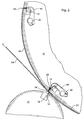
- FIG. 2 shows a detailed view of the cutting gap 09 and its surroundings according to a first embodiment of the invention.
- Two of the seven spiked strips 16 of the Transport cylinder 11 are shown in FIG. 2 and with mandaturologyn 16 '; 16 " designated. Both are each pivotable about a shaft 22 and carry Pointing needles 23, which are oriented so that their out of the scope of Transport cylinder 11 outstanding tip in each case further from the center of the shaft 22nd is removed as their lying within the transport cylinder 11 base.
- the point needles 23 of the spur strip 16 ' are in a comparatively far extended Position in which they have previously gone through the cutting gap 08. This same Position is drawn at the location of the spur strip 16 "dashed.
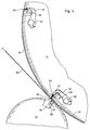
- Fig. 3 shows an alternative embodiment of the transport cylinder 11 and the Cutting cylinder 13 in a partial section analogous to that of Fig. 2.
- the cutting cylinder 13th has for each cutting blade 14 a projecting beyond its outer circumference Strip 28, the cutting gap 09 each just before the associated cutting blade 14 goes through.
- a complementarily shaped groove 29 on the transport cylinder 11 is the Bar 28 in each gap passage opposite, so that the spur strip 16 a trailing edge region of the cut off from the inner web 03 signature 24th and the outer web 04 pushes into the groove 29. This will make the lagging Edge of the signature 27 and pulled the gap 26 open. It is therefore with this Design does not require that the spur strip 16 "after its passage through the cutting gap 09 pivots outwards again to create the gap 26.
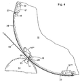
- FIG. 4 A third embodiment is again shown in FIG. 4 with reference to a partial section of FIG Transport cylinder 11 and the cutting cylinder 13 is shown.
- the cutting cylinder 13 is identical to that of Fig. 2, the transport cylinder 11 differs by the Arrangement of the shafts 22 about which the spurs 16 are pivotable. While at the embodiments of FIGS. 2 and 3, these waves 22 in the direction of rotation of the Transport cylinder 11 are located in front of the point needles 23, they are in the embodiment of Fig. 4 arranged behind this.
- the orientation of the puncturing needles 23 with respect to Surface of the transport cylinder 11 is the same in all cases, they are against the Surface normal slightly in the direction of rotation of the transport cylinder 11 forward inclined so that acting on on the puncturing needles 23 signatures acting Tension this holds pressed against the surface of the transport cylinder 11.
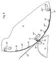
- a fourth embodiment of the cutting device is again shown in FIG. 5 in FIG. 4 analog view shown.
- Each of these segments 32 *, 32 ** ... sits down together from a plurality of flexible lamellae in the axial direction of the Transport cylinder 11 are arranged side by side and spaced by column 17.
- These column 17 are used in the transfer of finished cut products 24, 27 to the Jaw cylinder 18 each as outlet openings for tines one (not shown) Folding blade.
- the ends of the fins are each in the circumferential direction of the Transport cylinder 11 sliding head strips 33 anchored.
- the segment 32 * is a configuration in which the course of its slats of the Cylindrical shape of the transport cylinder 11 corresponds. After passage of such Segment 32 * through the cutting gaps 09 whose head strips 33, z. B. controlled by a (not shown) cam, shifted towards each other, so its lamellae, as shown by dashed lines on the segment 32 **, one over the circumference of the Forming transport cylinder 11 protruding projection. In consequence of this projection is the measured along the surface of the transport cylinder 11 distance between the Punctuation strips 16 ** and 16 *** larger than the one between the Puncture strips 16 * and 16 ** the latter corresponds to the length of the signatures 24 generated at the cutting gap 08; 27.
- the Bulge of the segment 32 ** therefore causes between the signatures 24 and 27 the gap 26 is formed, into which the cutting blade 14 of the cutting cylinder 13 engage can.
- a modified embodiment of the cutting device differs from that in Fig. 1 shown by the fact that they only a single inlet 01; 02 for a single too cutting path 03; 04 has.
- FIG taken the web 03 and the cutting cylinder 12 as not available be accepted.
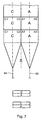
- the second transverse cutting device 11, 13 is on the circumference of the transport cylinder eleventh arranged out of phase cutting.
- the section of the first transverse cutting device 11, 12 takes place on the transport cylinder 11 short beside, in particular 10 mm next to, the other cut of the second Cross cutting device 11, 13.
- the first and second cross-cutting devices 11, 13 are in the circumferential direction on Transport cylinder 11 is arranged.
- jaw cylinder 18 can in all modes of operation also another Transport cylinder be followed to take over the signatures, in turn a Jaw cylinder or a belt system can be connected downstream.
- each of the tracks 03; 04 same patterns A and B in succession, d. H. has in the transport direction.
- These patterns A and B are preferably with printed at least one forme cylinder of a printing unit, the same on the circumference Pattern A or B is wearing.
- the tracks 03; 04 are superimposed, so that Signatures with superimposed patterns A and B arise, each in the gap 17th go over to the following Falklappenzylinder 18. This must be the Transport cylinder 11 does not necessarily have an odd division, sondem may also have an even division, preferably greater than 4 or 6.
- Patterns A, B, C, D preferably each designate two newspaper pages, where A1, A2; B1, B2; C1, C2; D1, D2 each denote a newspaper page.
- Bahn 03 is at least one track 03; 04 to understand Preferably, however, one of several superimposed webs is below each 03; 04 existing strand to understand.
- the tracks 03; 04 each printed with form cylinders of printing units be either a pattern A or B on the circumference (simple scope) or wear two patterns A and B on the circumference (double circumference).
- double-circumference form cylinder can have two same patterns A, A and B, B or two different patterns A, B be arranged on the circumference.
- the tracks carry 03; 04 in a first mode of operation in succession Patterns A and C, and it will be on the transport cylinder 11 in a row at each Turn same products made and directly to the subsequent ones Jaw cylinder 18 delivered.
- the webs 03; 04 alternating in a row Patterns A, B and C, D which in a first revolution of the odd number of fields provided transport cylinder 11 ( collecting cylinder) alternately on the Transport cylinder 11 are stored and in the second revolution in addition to a second layer of the folding product part are provided.
Landscapes
- Life Sciences & Earth Sciences (AREA)
- Forests & Forestry (AREA)
- Engineering & Computer Science (AREA)
- Mechanical Engineering (AREA)
- Folding Of Thin Sheet-Like Materials, Special Discharging Devices, And Others (AREA)
- Auxiliary Devices For And Details Of Packaging Control (AREA)
- Discharge By Other Means (AREA)
- Feeding Of Articles By Means Other Than Belts Or Rollers (AREA)
- Electrical Discharge Machining, Electrochemical Machining, And Combined Machining (AREA)
- Threshing Machine Elements (AREA)
- Branching, Merging, And Special Transfer Between Conveyors (AREA)
- Glass Compositions (AREA)
- Liquid Crystal (AREA)
- Insulated Conductors (AREA)
Claims (11)
- Dispositif de transport dans un appareil de pliage, comprenant un cylindre de transport (11), pour le transport de signatures (24 ; 27), au cylindre de transport (11) étant associé au moins un autre cylindre (12), une position de l'extrémité arrière de la signature étant modifiable sur le cylindre de transport (11), l'autre cylindre (12) présentant une bande (28) prolongeant son extrémité, pressant sur la signature, caractérisé en ce que le cylindre de transport (11) présente une cannelure (29) coopérant avec la bande (28).
- Dispositif de transport selon la revendication 1, caractérisé en ce que le cylindre (12) est réalisé sous la forme de cylindre de découpage (13) et présente au moins une lame de découpage (14).
- Dispositif de transport selon la revendication 1, caractérisé en ce que la bande (28) est localement fixe sur le cylindre (12) rotatif.
- Dispositif de transport dans un appareil de pliage, muni d'un cylindre de transport (11), présentant au moins un dispositif de maintien (16 ; 16' ; 16" ; 16* ; 16** ; 16***) modifiable en direction périphérique pour le transport de signatures, le dispositif de maintien (16 ; 16' ; 16" ; 16* ; 16** ; 16***) présentant en direction périphérique trois positions, sachant que, en une première position, le dispositif de maintien est disposé en recevant une première signature (24) ou une première couche de signatures (24), où, en une deuxième position, le dispositif de maintien (16 ; 16' ; 16" ; 16* ; 16**; 16***) est disposée en recevant une deuxième signature (27) ou une deuxième couche de signature (27), sachant que la deuxième position, en se référant à la direction de transport du cylindre de transport (11), est située derrière la première position, caractérisé en ce que, en une troisième position, située à l'avant de la première position, en se référant à la direction de transport du cylindre de transport (11) sont logées au moins deux couches de signatures (24 ; 27).
- Dispositif de transport selon la revendication 4, caractérisé en ce que le déplacement du dispositif de maintien (16 ; 16' ; 16" ; 16* ; 16** ; 16***) en direction périphérique est couplé à un déplacement en direction radiale.
- Dispositif de transport selon la revendication 5, caractérisé en ce que le dispositif de maintien (16 ; 16' ; 16" ; 16* ; 16** ; 16***), à la deuxième position, est disposé le plus profondément en direction radiale.
- Dispositif de transport selon la revendication 5, caractérisé en ce que le dispositif de maintien (16 ; 16' ; 16" ; 16* ; 16** ; 16***), à la troisième position, est disposé le plus haut en direction radiale.
- Dispositif de transport selon la revendication 1, caractérisé en ce que, en plus de la bande (28) et de la cannelure (29), est disposé un dispositif de maintien (16 ; 16' ; 16" ; 16* ; 16** ; 16***) pour modifier une position d'une extrémité avant de la signature (24 ; 27).
- Dispositif de transport selon la revendication 4, caractérisé en ce que, en plus du dispositif de maintien (16 ; 16' ; 16" ; 16* ; 16** ; 16***), est disposé un autre dispositif (29, 28), pour modifier la position de l'extrémité arrière de la troisième signature (24) reçue.
- Dispositif de transport selon la revendication 8 ou 9, caractérisé en ce que les deux dispositifs (16 ; 28, 29) sont disposés en agissant à des moments différents sur les signatures (24 ; 27).
- Dispositif de transport selon la revendication 4 ou 8, caractérisé en ce que le dispositif de maintien (16 ; 16' ; 16" ; 16* ; 16** ; 16***) est réalisé sous la forme de bandes de pointure.
Priority Applications (2)
| Application Number | Priority Date | Filing Date | Title |
|---|---|---|---|
| DE20320941U DE20320941U1 (de) | 2002-03-04 | 2003-02-28 | Transportvorrichtung |
| EP04105612A EP1505028A3 (fr) | 2002-03-04 | 2003-02-28 | Dispositif de transport |
Applications Claiming Priority (3)
| Application Number | Priority Date | Filing Date | Title |
|---|---|---|---|
| DE10209213 | 2002-03-04 | ||
| DE10209213A DE10209213B4 (de) | 2002-03-04 | 2002-03-04 | Transportvorrichtung |
| PCT/DE2003/000674 WO2003074400A1 (fr) | 2002-03-04 | 2003-02-28 | Dispositif de transport |
Related Child Applications (1)
| Application Number | Title | Priority Date | Filing Date |
|---|---|---|---|
| EP04105612A Division EP1505028A3 (fr) | 2002-03-04 | 2003-02-28 | Dispositif de transport |
Publications (2)
| Publication Number | Publication Date |
|---|---|
| EP1480902A1 EP1480902A1 (fr) | 2004-12-01 |
| EP1480902B1 true EP1480902B1 (fr) | 2005-11-09 |
Family
ID=27770933
Family Applications (2)
| Application Number | Title | Priority Date | Filing Date |
|---|---|---|---|
| EP03743294A Expired - Lifetime EP1480902B1 (fr) | 2002-03-04 | 2003-02-28 | Dispositif de transport |
| EP04105612A Withdrawn EP1505028A3 (fr) | 2002-03-04 | 2003-02-28 | Dispositif de transport |
Family Applications After (1)
| Application Number | Title | Priority Date | Filing Date |
|---|---|---|---|
| EP04105612A Withdrawn EP1505028A3 (fr) | 2002-03-04 | 2003-02-28 | Dispositif de transport |
Country Status (6)
| Country | Link |
|---|---|
| US (2) | US7311651B2 (fr) |
| EP (2) | EP1480902B1 (fr) |
| AT (1) | ATE309167T1 (fr) |
| AU (1) | AU2003227015A1 (fr) |
| DE (3) | DE10209213B4 (fr) |
| WO (1) | WO2003074400A1 (fr) |
Families Citing this family (4)
| Publication number | Priority date | Publication date | Assignee | Title |
|---|---|---|---|---|
| US7896795B2 (en) * | 2005-10-25 | 2011-03-01 | Goss International Americas, Inc. | Folder with signature support |
| DE202009018120U1 (de) * | 2009-12-16 | 2011-01-27 | Manroland Ag | Vorrichtung zur Verarbeitung von aus mehreren Papierlagen bestehenden Druckprodukten sowie Perforiermesser |
| US20130269493A1 (en) * | 2012-04-17 | 2013-10-17 | Goss International Americas, Inc. | Variable cutoff in a cutter folder |
| US11618177B1 (en) | 2022-04-12 | 2023-04-04 | Bradley W Boesel | Orbital knife |
Family Cites Families (37)
| Publication number | Priority date | Publication date | Assignee | Title |
|---|---|---|---|---|
| US730892A (en) * | 1902-03-26 | 1903-06-16 | Goss Printing Press Co Ltd | Delivery apparatus for printing-presses. |
| US1798910A (en) * | 1929-06-13 | 1931-03-31 | Goss Printing Press Co Ltd | Sheet cutting and handling mechanism |
| US2211046A (en) * | 1938-04-01 | 1940-08-13 | Cottrell C B & Sons Co | Cutting and folding machine |
| US2364504A (en) * | 1942-06-24 | 1944-12-05 | Hoe & Co R | Stapling mechanism for rotary printing machines |
| CH278305A (de) * | 1949-05-25 | 1951-10-15 | Maschf Augsburg Nuernberg Ag | Verfahren und Einrichtung zum Sammeln von Bogen auf dem Falzzylinder von Rotationsdruckmaschinen. |
| AT222671B (de) * | 1959-01-22 | 1962-08-10 | Winkler Fallert & Co Maschf | Falzapparat |
| DE1611283C2 (de) * | 1967-08-09 | 1975-11-27 | Koenig & Bauer Ag, 8700 Wuerzburg | Schneid- und Falzapparat an Rollenrotationsmaschinen |
| DE1955351C3 (de) * | 1969-11-04 | 1975-07-24 | Roland Offsetmaschinenfabrik Faber & Schleicher Ag, 6050 Offenbach | Vorrichtung zum Verschwenken des Falzmessers eines Falzmesserzylinders |
| DE2142902A1 (de) * | 1971-08-27 | 1973-03-08 | Dornier Ag | Vorrichtung zum schneiden, sammeln und falzen einer oder mehrerer ankommender papierbahnen |
| DE2805643C2 (de) | 1978-02-10 | 1986-08-07 | M.A.N. Maschinenfabrik Augsburg-Nürnberg AG, 8900 Augsburg | Falzwerk für Rollen-Rotationsdruckmaschinen, bei welchem aufeinander gesammelte Druckbogen mit Hilfe einer Verdrängerleiste auslenkbar sind |
| DE2936768C2 (de) * | 1979-09-12 | 1986-02-20 | M.A.N.- Roland Druckmaschinen AG, 6050 Offenbach | Verstellbare Falzvorrichtung für Rotationsdruckmaschinen |
| US4445881A (en) * | 1982-03-31 | 1984-05-01 | Publishers Equipment Corporation | Method and apparatus for improving newspaper folding and cutting mechanisms |
| US4519597A (en) * | 1984-05-10 | 1985-05-28 | The Lehigh Press, Inc. | Folding apparatus with compound tucker blade motion |
| JPS61182798A (ja) * | 1985-02-05 | 1986-08-15 | 福崎 英機 | ダイカツタ−ロ−ル |
| DE3527710A1 (de) * | 1985-08-02 | 1987-02-12 | Roland Man Druckmasch | Falzapparat zum querfalzen zugeschnittener druckexemplare |
| US4754959A (en) * | 1985-08-02 | 1988-07-05 | M.A.N. Roland Druckmaschinen Aktiengesellschaft | Folding apparatus for transverse folding and transporting of two types of printed substrates |
| DE3726239A1 (de) * | 1987-08-07 | 1989-02-16 | Frankenthal Ag Albert | Falzapparat |
| US5037365A (en) * | 1989-12-20 | 1991-08-06 | Harris Graphics Corporation | Folder with belt speed control |
| DE4120628A1 (de) * | 1991-06-22 | 1992-12-24 | Roland Man Druckmasch | Einrichtung zum querschneiden und/oder -perforieren von bahnen |
| DE4316134C2 (de) * | 1993-05-13 | 1997-03-13 | Heidelberger Druckmasch Ag | Verfahren zur Querfalzung von Bahnen sowie Falzapparat zur Durchführung des Verfahrens |
| DE4340858C2 (de) * | 1993-12-01 | 1998-02-12 | Koenig & Bauer Albert Ag | Zylinder |
| DE4342037C1 (de) * | 1993-12-09 | 1995-03-02 | Frankenthal Ag Albert | Verfahren und Vorrichtung zum Querfalzen von Signaturen |
| DE4344362C2 (de) * | 1993-12-24 | 1998-02-26 | Koenig & Bauer Albert Ag | Vorrichtung zum Herstellen von Falzprodukten |
| DE4424919C1 (de) * | 1994-07-14 | 1995-09-28 | Koenig & Bauer Ag | Schneidmesserbalken eines Schneidzylinders in Falzwerken von Rollenrotationsdruckmaschinen |
| US5707330A (en) * | 1995-03-24 | 1998-01-13 | Goss Graphic Systems, Inc. | Folding machine for folding and cutting webs in a rotary printing press |
| EP0734988B1 (fr) * | 1995-03-25 | 2001-09-26 | Koenig & Bauer Aktiengesellschaft | Méthode et appareil pour mettre en mouvement des aiguilles de perforation |
| ES2149549T3 (es) * | 1996-10-15 | 2000-11-01 | Komori Printing Mach | Plegadora sin agujas. |
| DE59703827D1 (de) * | 1996-10-25 | 2001-07-26 | Koenig & Bauer Ag | Falzapparat |
| US6093139A (en) * | 1998-01-27 | 2000-07-25 | Heidelberger Druckmaschinen Ag | Folding apparatus for rotary printing presses |
| US6551227B1 (en) * | 1999-12-08 | 2003-04-22 | Heidelberger Druckmaschinen Ag | Device for seizing of flat material on a transporting surface |
| GB2358898B (en) * | 1999-12-09 | 2002-04-24 | Usui Kokusai Sangyo Kk | Diesel engine fuel injection pipe |
| US6652437B1 (en) * | 1999-12-28 | 2003-11-25 | Heidelberger Druckmaschinen Ag | Actuated product seizing element in a folder apparatus |
| US7338425B1 (en) | 2000-01-12 | 2008-03-04 | Goss International Americas, Inc. | Variable length cutting device |
| US6279890B1 (en) * | 2000-04-11 | 2001-08-28 | Goss Graphic Systems, Inc. | Combination rotary and jaw folder for a printing press |
| JP3983547B2 (ja) * | 2000-05-17 | 2007-09-26 | ケーニツヒ ウント バウエル アクチエンゲゼルシヤフト | 折り装置 |
| JP2001341932A (ja) * | 2000-06-01 | 2001-12-11 | Toshiba Tec Corp | ロータリカッタおよびプリンタユニット |
| JP3697694B2 (ja) * | 2002-05-09 | 2005-09-21 | 株式会社東京機械製作所 | 輪転機の折部の咥え装置 |
-
2002
- 2002-03-04 DE DE10209213A patent/DE10209213B4/de not_active Expired - Fee Related
-
2003
- 2003-02-28 EP EP03743294A patent/EP1480902B1/fr not_active Expired - Lifetime
- 2003-02-28 EP EP04105612A patent/EP1505028A3/fr not_active Withdrawn
- 2003-02-28 DE DE50301616T patent/DE50301616D1/de not_active Expired - Lifetime
- 2003-02-28 US US10/505,873 patent/US7311651B2/en not_active Expired - Fee Related
- 2003-02-28 AT AT03743294T patent/ATE309167T1/de active
- 2003-02-28 DE DE20320941U patent/DE20320941U1/de not_active Expired - Lifetime
- 2003-02-28 AU AU2003227015A patent/AU2003227015A1/en not_active Abandoned
- 2003-02-28 WO PCT/DE2003/000674 patent/WO2003074400A1/fr not_active Ceased
-
2006
- 2006-01-24 US US11/337,566 patent/US20060128544A1/en not_active Abandoned
Also Published As
| Publication number | Publication date |
|---|---|
| US20060128544A1 (en) | 2006-06-15 |
| DE20320941U1 (de) | 2005-06-30 |
| EP1480902A1 (fr) | 2004-12-01 |
| US20050107234A1 (en) | 2005-05-19 |
| EP1505028A3 (fr) | 2005-03-02 |
| ATE309167T1 (de) | 2005-11-15 |
| US7311651B2 (en) | 2007-12-25 |
| WO2003074400A1 (fr) | 2003-09-12 |
| AU2003227015A1 (en) | 2003-09-16 |
| DE50301616D1 (de) | 2005-12-15 |
| DE10209213B4 (de) | 2004-03-25 |
| DE10209213A1 (de) | 2003-09-25 |
| EP1505028A2 (fr) | 2005-02-09 |
| WO2003074400B1 (fr) | 2004-03-04 |
Similar Documents
| Publication | Publication Date | Title |
|---|---|---|
| EP0859733B1 (fr) | Procede et dispositif permettant de produire des journaux a couches multiples avec une partie de format tabloide | |
| DE60111037T2 (de) | Kombination einer rotationsfalzmaschine mit einem falzklappenzylinder für eine druckmaschine | |
| EP2039640B1 (fr) | Dispositif et procédé de production d'un produit d'impression et produit d'impression | |
| EP2177465A2 (fr) | Plieuse et procédé de pliage | |
| EP1922276B1 (fr) | Appareil de pliage | |
| EP2030935B1 (fr) | Dispositif de coupe transversale d'au moins une bande de matériau | |
| EP1480902B1 (fr) | Dispositif de transport | |
| DE10238736A1 (de) | Verfahren und Vorrichtung zum Falzen eines Druckprodukts | |
| EP1103508A2 (fr) | Dispositif de pliage d'exemplaires plats | |
| EP1483189B1 (fr) | Dispositif de coupe | |
| EP0222150B1 (fr) | Plieuse à lames engageantes | |
| EP1802466A2 (fr) | Procede et imprimante pour produire des produits imprimes avec plusieurs livres | |
| DE102014205939A1 (de) | Verfahren und Vorrichtung zur Herstellung eines Druckproduktes sowie Druckprodukt | |
| EP1156006B1 (fr) | Dispositif de pliage à tambour avec un cylindre à lame de pliage | |
| DE102006057453B4 (de) | Falzapparat | |
| EP1620343B1 (fr) | Appareil de pliage roues doté d'un dispositif de coupe pour couper en travers au moins une bande de matériau | |
| EP4282657A1 (fr) | Plieuse d'une machine d'impression offset á bobines et machine d'impression offset á bobines | |
| DE102004005807B4 (de) | Falzapparat | |
| DE102014222387B4 (de) | Verfahren zur Herstellung eines Druckproduktes sowie Druckprodukt | |
| DE102016216429B4 (de) | Druckprodukt, Verfahren und Rollendruckmaschine zur Herstellung eines Druckproduktes | |
| DE102012203102B4 (de) | Rollendruckmaschine sowie Verfahren zum Betrieb einer Rollendruckmaschine | |
| DE102014207835B4 (de) | Verfahren und Druckmaschine zur Herstellung von Druckprodukten | |
| DE2060989A1 (de) | Vorrichtung zum Vereinzeln von gestapelten Papierbogen,insbesondere von mehrfach gefalteten Papierbogen,wie z.B.Zeitungsbeilagen | |
| DE102011102542A1 (de) | Falzwerk |
Legal Events
| Date | Code | Title | Description |
|---|---|---|---|
| PUAI | Public reference made under article 153(3) epc to a published international application that has entered the european phase |
Free format text: ORIGINAL CODE: 0009012 |
|
| 17P | Request for examination filed |
Effective date: 20040427 |
|
| AK | Designated contracting states |
Kind code of ref document: A1 Designated state(s): AT BE BG CH CY CZ DE DK EE ES FI FR GB GR HU IE IT LI LU MC NL PT SE SI SK TR |
|
| AX | Request for extension of the european patent |
Extension state: AL LT LV MK RO |
|
| GRAP | Despatch of communication of intention to grant a patent |
Free format text: ORIGINAL CODE: EPIDOSNIGR1 |
|
| GRAS | Grant fee paid |
Free format text: ORIGINAL CODE: EPIDOSNIGR3 |
|
| GRAA | (expected) grant |
Free format text: ORIGINAL CODE: 0009210 |
|
| AK | Designated contracting states |
Kind code of ref document: B1 Designated state(s): AT BE BG CH CY CZ DE DK EE ES FI FR GB GR HU IE IT LI LU MC NL PT SE SI SK TR |
|
| PG25 | Lapsed in a contracting state [announced via postgrant information from national office to epo] |
Ref country code: NL Free format text: LAPSE BECAUSE OF FAILURE TO SUBMIT A TRANSLATION OF THE DESCRIPTION OR TO PAY THE FEE WITHIN THE PRESCRIBED TIME-LIMIT Effective date: 20051109 Ref country code: SI Free format text: LAPSE BECAUSE OF FAILURE TO SUBMIT A TRANSLATION OF THE DESCRIPTION OR TO PAY THE FEE WITHIN THE PRESCRIBED TIME-LIMIT Effective date: 20051109 Ref country code: FI Free format text: LAPSE BECAUSE OF FAILURE TO SUBMIT A TRANSLATION OF THE DESCRIPTION OR TO PAY THE FEE WITHIN THE PRESCRIBED TIME-LIMIT Effective date: 20051109 Ref country code: CZ Free format text: LAPSE BECAUSE OF FAILURE TO SUBMIT A TRANSLATION OF THE DESCRIPTION OR TO PAY THE FEE WITHIN THE PRESCRIBED TIME-LIMIT Effective date: 20051109 Ref country code: SK Free format text: LAPSE BECAUSE OF FAILURE TO SUBMIT A TRANSLATION OF THE DESCRIPTION OR TO PAY THE FEE WITHIN THE PRESCRIBED TIME-LIMIT Effective date: 20051109 Ref country code: IE Free format text: LAPSE BECAUSE OF FAILURE TO SUBMIT A TRANSLATION OF THE DESCRIPTION OR TO PAY THE FEE WITHIN THE PRESCRIBED TIME-LIMIT Effective date: 20051109 |
|
| REG | Reference to a national code |
Ref country code: GB Ref legal event code: FG4D Free format text: NOT ENGLISH |
|
| REG | Reference to a national code |
Ref country code: CH Ref legal event code: EP |
|
| REG | Reference to a national code |
Ref country code: IE Ref legal event code: FG4D Free format text: LANGUAGE OF EP DOCUMENT: GERMAN |
|
| REF | Corresponds to: |
Ref document number: 50301616 Country of ref document: DE Date of ref document: 20051215 Kind code of ref document: P |
|
| REG | Reference to a national code |
Ref country code: SE Ref legal event code: TRGR |
|
| GBT | Gb: translation of ep patent filed (gb section 77(6)(a)/1977) |
Effective date: 20060108 |
|
| PG25 | Lapsed in a contracting state [announced via postgrant information from national office to epo] |
Ref country code: BG Free format text: LAPSE BECAUSE OF FAILURE TO SUBMIT A TRANSLATION OF THE DESCRIPTION OR TO PAY THE FEE WITHIN THE PRESCRIBED TIME-LIMIT Effective date: 20060209 Ref country code: GR Free format text: LAPSE BECAUSE OF FAILURE TO SUBMIT A TRANSLATION OF THE DESCRIPTION OR TO PAY THE FEE WITHIN THE PRESCRIBED TIME-LIMIT Effective date: 20060209 Ref country code: DK Free format text: LAPSE BECAUSE OF FAILURE TO SUBMIT A TRANSLATION OF THE DESCRIPTION OR TO PAY THE FEE WITHIN THE PRESCRIBED TIME-LIMIT Effective date: 20060209 |
|
| PG25 | Lapsed in a contracting state [announced via postgrant information from national office to epo] |
Ref country code: ES Free format text: LAPSE BECAUSE OF FAILURE TO SUBMIT A TRANSLATION OF THE DESCRIPTION OR TO PAY THE FEE WITHIN THE PRESCRIBED TIME-LIMIT Effective date: 20060220 |
|
| PG25 | Lapsed in a contracting state [announced via postgrant information from national office to epo] |
Ref country code: LU Free format text: LAPSE BECAUSE OF NON-PAYMENT OF DUE FEES Effective date: 20060228 Ref country code: MC Free format text: LAPSE BECAUSE OF NON-PAYMENT OF DUE FEES Effective date: 20060228 Ref country code: BE Free format text: LAPSE BECAUSE OF NON-PAYMENT OF DUE FEES Effective date: 20060228 |
|
| PG25 | Lapsed in a contracting state [announced via postgrant information from national office to epo] |
Ref country code: PT Free format text: LAPSE BECAUSE OF FAILURE TO SUBMIT A TRANSLATION OF THE DESCRIPTION OR TO PAY THE FEE WITHIN THE PRESCRIBED TIME-LIMIT Effective date: 20060410 |
|
| NLV1 | Nl: lapsed or annulled due to failure to fulfill the requirements of art. 29p and 29m of the patents act | ||
| PG25 | Lapsed in a contracting state [announced via postgrant information from national office to epo] |
Ref country code: HU Free format text: LAPSE BECAUSE OF FAILURE TO SUBMIT A TRANSLATION OF THE DESCRIPTION OR TO PAY THE FEE WITHIN THE PRESCRIBED TIME-LIMIT Effective date: 20060510 |
|
| ET | Fr: translation filed | ||
| REG | Reference to a national code |
Ref country code: IE Ref legal event code: FD4D |
|
| PLBE | No opposition filed within time limit |
Free format text: ORIGINAL CODE: 0009261 |
|
| STAA | Information on the status of an ep patent application or granted ep patent |
Free format text: STATUS: NO OPPOSITION FILED WITHIN TIME LIMIT |
|
| 26N | No opposition filed |
Effective date: 20060810 |
|
| BERE | Be: lapsed |
Owner name: KOENIG & BAUER A.G. Effective date: 20060228 |
|
| PG25 | Lapsed in a contracting state [announced via postgrant information from national office to epo] |
Ref country code: EE Free format text: LAPSE BECAUSE OF FAILURE TO SUBMIT A TRANSLATION OF THE DESCRIPTION OR TO PAY THE FEE WITHIN THE PRESCRIBED TIME-LIMIT Effective date: 20051109 |
|
| PG25 | Lapsed in a contracting state [announced via postgrant information from national office to epo] |
Ref country code: TR Free format text: LAPSE BECAUSE OF FAILURE TO SUBMIT A TRANSLATION OF THE DESCRIPTION OR TO PAY THE FEE WITHIN THE PRESCRIBED TIME-LIMIT Effective date: 20051109 |
|
| PG25 | Lapsed in a contracting state [announced via postgrant information from national office to epo] |
Ref country code: CY Free format text: LAPSE BECAUSE OF FAILURE TO SUBMIT A TRANSLATION OF THE DESCRIPTION OR TO PAY THE FEE WITHIN THE PRESCRIBED TIME-LIMIT Effective date: 20051109 |
|
| PGFP | Annual fee paid to national office [announced via postgrant information from national office to epo] |
Ref country code: IT Payment date: 20110218 Year of fee payment: 9 Ref country code: CH Payment date: 20110225 Year of fee payment: 9 Ref country code: AT Payment date: 20110223 Year of fee payment: 9 Ref country code: SE Payment date: 20110222 Year of fee payment: 9 |
|
| PGFP | Annual fee paid to national office [announced via postgrant information from national office to epo] |
Ref country code: FR Payment date: 20120229 Year of fee payment: 10 |
|
| PGFP | Annual fee paid to national office [announced via postgrant information from national office to epo] |
Ref country code: DE Payment date: 20120315 Year of fee payment: 10 |
|
| PGFP | Annual fee paid to national office [announced via postgrant information from national office to epo] |
Ref country code: GB Payment date: 20120221 Year of fee payment: 10 |
|
| REG | Reference to a national code |
Ref country code: CH Ref legal event code: PL |
|
| REG | Reference to a national code |
Ref country code: SE Ref legal event code: EUG |
|
| PG25 | Lapsed in a contracting state [announced via postgrant information from national office to epo] |
Ref country code: SE Free format text: LAPSE BECAUSE OF NON-PAYMENT OF DUE FEES Effective date: 20120301 Ref country code: LI Free format text: LAPSE BECAUSE OF NON-PAYMENT OF DUE FEES Effective date: 20120229 Ref country code: CH Free format text: LAPSE BECAUSE OF NON-PAYMENT OF DUE FEES Effective date: 20120229 |
|
| PG25 | Lapsed in a contracting state [announced via postgrant information from national office to epo] |
Ref country code: IT Free format text: LAPSE BECAUSE OF NON-PAYMENT OF DUE FEES Effective date: 20120228 |
|
| REG | Reference to a national code |
Ref country code: AT Ref legal event code: MM01 Ref document number: 309167 Country of ref document: AT Kind code of ref document: T Effective date: 20120228 |
|
| PG25 | Lapsed in a contracting state [announced via postgrant information from national office to epo] |
Ref country code: AT Free format text: LAPSE BECAUSE OF NON-PAYMENT OF DUE FEES Effective date: 20120228 |
|
| GBPC | Gb: european patent ceased through non-payment of renewal fee |
Effective date: 20130228 |
|
| REG | Reference to a national code |
Ref country code: FR Ref legal event code: ST Effective date: 20131031 |
|
| REG | Reference to a national code |
Ref country code: DE Ref legal event code: R119 Ref document number: 50301616 Country of ref document: DE Effective date: 20130903 |
|
| PG25 | Lapsed in a contracting state [announced via postgrant information from national office to epo] |
Ref country code: DE Free format text: LAPSE BECAUSE OF NON-PAYMENT OF DUE FEES Effective date: 20130903 Ref country code: GB Free format text: LAPSE BECAUSE OF NON-PAYMENT OF DUE FEES Effective date: 20130228 Ref country code: FR Free format text: LAPSE BECAUSE OF NON-PAYMENT OF DUE FEES Effective date: 20130228 |