EP1481441B1 - Diversityantenne für einen unii-zugangspunkt - Google Patents
Diversityantenne für einen unii-zugangspunkt Download PDFInfo
- Publication number
- EP1481441B1 EP1481441B1 EP03717925A EP03717925A EP1481441B1 EP 1481441 B1 EP1481441 B1 EP 1481441B1 EP 03717925 A EP03717925 A EP 03717925A EP 03717925 A EP03717925 A EP 03717925A EP 1481441 B1 EP1481441 B1 EP 1481441B1
- Authority
- EP
- European Patent Office
- Prior art keywords
- diversity antenna
- antenna system
- diversity
- access point
- antenna
- Prior art date
- Legal status (The legal status is an assumption and is not a legal conclusion. Google has not performed a legal analysis and makes no representation as to the accuracy of the status listed.)
- Expired - Lifetime
Links
- 238000009434 installation Methods 0.000 claims abstract description 14
- 239000004065 semiconductor Substances 0.000 claims description 6
- 238000004891 communication Methods 0.000 description 6
- 230000008901 benefit Effects 0.000 description 5
- 230000005855 radiation Effects 0.000 description 5
- 238000010586 diagram Methods 0.000 description 4
- 230000001419 dependent effect Effects 0.000 description 2
- 230000003071 parasitic effect Effects 0.000 description 2
- 229910001218 Gallium arsenide Inorganic materials 0.000 description 1
- 230000033228 biological regulation Effects 0.000 description 1
- 230000008878 coupling Effects 0.000 description 1
- 238000010168 coupling process Methods 0.000 description 1
- 238000005859 coupling reaction Methods 0.000 description 1
- 238000000034 method Methods 0.000 description 1
- 230000005404 monopole Effects 0.000 description 1
- 230000001629 suppression Effects 0.000 description 1
Images


Classifications
-
- H—ELECTRICITY
- H01—ELECTRIC ELEMENTS
- H01Q—ANTENNAS, i.e. RADIO AERIALS
- H01Q21/00—Antenna arrays or systems
- H01Q21/28—Combinations of substantially independent non-interacting antenna units or systems
-
- H—ELECTRICITY
- H01—ELECTRIC ELEMENTS
- H01Q—ANTENNAS, i.e. RADIO AERIALS
- H01Q1/00—Details of, or arrangements associated with, antennas
- H01Q1/08—Means for collapsing antennas or parts thereof
- H01Q1/084—Pivotable antennas
-
- H—ELECTRICITY
- H01—ELECTRIC ELEMENTS
- H01Q—ANTENNAS, i.e. RADIO AERIALS
- H01Q1/00—Details of, or arrangements associated with, antennas
- H01Q1/12—Supports; Mounting means
-
- H—ELECTRICITY
- H01—ELECTRIC ELEMENTS
- H01Q—ANTENNAS, i.e. RADIO AERIALS
- H01Q25/00—Antennas or antenna systems providing at least two radiating patterns
- H01Q25/002—Antennas or antenna systems providing at least two radiating patterns providing at least two patterns of different beamwidth; Variable beamwidth antennas
-
- H—ELECTRICITY
- H01—ELECTRIC ELEMENTS
- H01Q—ANTENNAS, i.e. RADIO AERIALS
- H01Q3/00—Arrangements for changing or varying the orientation or the shape of the directional pattern of the waves radiated from an antenna or antenna system
- H01Q3/02—Arrangements for changing or varying the orientation or the shape of the directional pattern of the waves radiated from an antenna or antenna system using mechanical movement of antenna or antenna system as a whole
-
- H—ELECTRICITY
- H01—ELECTRIC ELEMENTS
- H01Q—ANTENNAS, i.e. RADIO AERIALS
- H01Q3/00—Arrangements for changing or varying the orientation or the shape of the directional pattern of the waves radiated from an antenna or antenna system
- H01Q3/24—Arrangements for changing or varying the orientation or the shape of the directional pattern of the waves radiated from an antenna or antenna system varying the orientation by switching energy from one active radiating element to another, e.g. for beam switching
Definitions
- This invention relates to wireless communications systems and more specifically to a diversity antenna for a UNII band access point.
- the U.S. Federal Communications Commission's (“FCC”) promulgated rules for the Unlicensed National Information Infrastructure (“UNII”) bands, 5.15 - 5.35 GHz and 5725 MHz to 5825 MHz. There are three UNII bands, each are 100 MHz bands. Of interest in the present application are the UNII-1 band, 5150-5250 MHz and the UNII -2 band, 5250-5350 MHz.
- the UNII-1 band is reserved for indoor wireless use.
- the UNII-2 band is designed for indoor or outdoor wireless LANs and allows for a higher powered, customizable antenna.
- the FCC UNII rules require captured antennas for all products that operate in the UNII-1 band. Effectively, this rule does not allow a user to change antennas in the field.
- Access Points benefit from a variety of antennas that may be chosen or spatially oriented to suit the installation. Most applications can be installed with either a dipole antenna for an omni-directional coverage pattern or an external patch antenna for a directional coverage pattern.
- APs and antennas may be mounted in a variety of environments. They may, for example, be mounted vertically on a wall, horizontally on a shelf, or hung from a ceiling.
- US 5,649,306 describes a radio communication device having a first housing element and a second housing element with the first housing element being movable between an extended and a closed position.
- the radio communication device has at least two antennas and switches provided to switch between antennas, dependent upon the position of the first housing element.
- a first antenna disposed in the first housing element may be a half-way dipole antenna or a loop type, patch type or monopole antenna.
- the second antenna may be a patch antenna integrated into a battery housing of the radio communications device.
- the radio communications device also has a third antenna in the form of a retractable whip antenna which is coupled in diversity with either the first or the second antenna, dependent upon the position of the first housing element.
- EP1168487A2 describes a switching and connecting arrangement for coupling external and internal antennas wherein the arrangement comprises a diversity switch for selecting a first or a second antenna.
- a first integrated antenna switch is forced mechanically to select a first external antenna instead of a first internal antenna when the first external antenna is coupled to the first antenna switch and to select the first internal antenna when it is disconnected.
- a second antenna switch is forced mechanically to select a second external antenna instead of a second internal antenna when the second external antenna is coupled to the switch and to select the second internal antenna when the second external antenna is disconnected.
- the present invention provides a diversity antenna system for an access point, as set out in claim 1.
- the present invention provides a diversity antenna system for an access point as set out in claim 2.
- the present invention also provides a wireless access point as set out in claim 12.
- An embodiment of the present invention provides an antenna system and a wireless access point suitable for UNII access points that conforms to the FCC UNII rules, offers the most flexibility matching the characteristic of the antenna to the installation requirement and has the benefits of a diversity antenna,
- a diversity antenna system embodying the invention provides a combination of a near omni-directional antenna (almost omni-directional in the H-plane), and an internal, configurable low gain patch array that are all built into the access point in accordance with the FCC requirements.
- the antenna system is preferably rotatable so that the correct antenna orientation can be achieved to allow for more optimal coverage.
- the antenna system When deploying the near-omni antennas, the antenna system is preferably rotated to the vertical and when deploying the patches, the system is preferably rotated to the horizontal.
- the present invention essentially provides the flexibility to meet the needs of the majority of access point installations encountered. The higher frequency of the UNII bands, 5 GHz, makes smaller geometry antennas possible within the product envelope.
- the near omni-directional antenna (near omni-antenna) is preferably constructed on the same printed circuit board (PCB) as the patch array. These antennas preferably have a (roughly) 180-degree 3-dB beamwidth and only about 10dB maximum side lobe suppression, mostly in the direction of the other near omni-directionat antenna.
- the directional antenna preferably comprises a typical TM10 mode rectangular patch antenna, probably realized with a stacked parasitic element to meet bandwidth requirements. Size and other physical dimensions determine the characteristics of the TM10 mode stacked patch antenna array.
- a means for selecting the antenna type may be provided by either a configuration utility at installation or a small mechanical detect switch could be utilized to sense the orientation of the antenna system. If the AP is mounted on the ceiling or on a bookshelf (or any horizontal mounting), the near omni-directional antenna should be used and the installer will rotate the antenna system to the upright position. The mechanical detect switch will open causing the near-omnis to be deployed. If the AP is mounted on a wall, the installer will rotate the antenna system to the horizontal position causing the detect switch to close, thus deploying the patch antennas.
- the present invention enables a single product to give a UNII 1-2 access point nearly all the required antenna flexibility of enterprise 2.4 GHz access points.
- the present invention provides adequate diversity for 5 GHz. OFDM systems are inherently robust against multipath conditions and the packet-by-packet diversity algorithms controlled by the MAC are applicable.
- the MAC diversity algorithm naturally converges to the strongest antenna as the default whether it is the near omni-directional antenna or the directional patch antenna, under normal use.
- the present invention would provide a huge degree of application flexibility at a very lost cost, if all the antennas are constructed on a single RF circuit board.
- the present invention utilizes the combination of captured near omni-directional antennas and internal patch antennas that are preferably built into a UNII access point in accordance with FCC requirements. This combination provides the flexibility to meet the needs of the majority of installations for an access point. Smaller geometry antennas are possible at 5 GHz.
- the near omni-directional antennas are an array of elements that are simple structures constructed on an RF circuit board, providing approximately 5-dBN gain.
- the entire antenna system can be rotated so that the near omnidirectional antennas can be perpendicular to the ground, even when the access point is mounted in a non-perpendicular orientation, as is well known in the art and utilized in common dipole designs.
- the directional antenna is a TM10 mode patch antenna design that provides a conventional hemispherical pattern suitable for vertically mounted access points.
- the antenna system is rotated to the horizontal position when deploying the patch antennas.
- the choice of antenna type is made with a detect switch in the antenna system housing that senses whether the antenna system is rotated vertically or horizontally.
- the antennas previously discussed are used.
- the installer chooses the antenna type to be used with the setup utility of the access point, and a control line from the radio MAC processor switches the antenna type. For example, if the installer wants a more hemispherical coverage pattern, he rotates the antenna system to the horizontal position, and selects "patch antenna" (or something similar) with the access point's setup utility.
- the MAC provides the control signal to do the switching.
- the antenna type (either omni-directional or directional) is selected (in practice) at the time of installation and it depends on the type of coverage pattern desired. The selection should be made based on how the access point is mounted. If the AP is mounted horizontally (for example, on the ceiling or on a shelf), then the near omni-directional antenna should be deployed. If the AP is mounted on a wall, the patch antenna should be used. This selectable antenna feature allows one single AP to be used in most mounting scenarios, even though all the antennas are integral to the AP itself.
- the MAC controls the diversity operation of the AP. That is, the MAC will determine whether the left antenna (of a given type) or the right antenna (of the same type) yields the best performance.
- the present invention enables a single product to provide a 5 GHz UNII access point with the flexibility to select antenna functionality similar to 2.4 GHz access points and yet still allow for a low cost solution.
- Both the near omni-directional antennas and the patch antennas are constructed on the same printed circuit board that is integral to the access point enclosure to satisfy the FCC regulations.
- the near omni antennas (along with diversity) provide a traditional circular coverage pattern.
- the TM10 mode patch antenna provides the traditional hemispherical pattern, suitable for corridor or narrow room coverage when the access point is mounted on a wall. This access point antenna system provides a large degree of application flexibility at a very low cost.
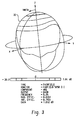
- FIG. 1 there is shown a radiation pattern for the typical near omnidirectional antenna.
- the antenna is aligned with the Z-axis.
- the radiation from the antenna propagates primarily in the X-Y axis, normal to the Z-axis.
- the Z-axis coverage of this antenna is very small, and for practical purposes non-existent.
- the near omni antenna can be deployed in such a manner that it would always be in the vertical position regardless of the orientation of the access point.
- FIG 2 shows the basic geometry of a circular TM10 mode patch antenna, generally designated 20.
- the radiator 21 of the typical TM10 antenna 20 for use in a UNII access point would be approximately 17 mm x 17 mm and have parasitic element deployed at a height of roughly 4mm above the circuit board depending on bandwidth requirements.
- Figure 3 shows the radiation pattern 30 from a TM10 mode patch as described in Figure 2 .
- the typical pattern of the TM10 mode patch antenna is hemispherical with E-plane 3-dB beamwidth of around 65 degrees and an H-plane 3-dB beamwidth of around 60 degrees in free space.
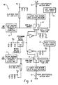
- FIG. 4 is a block diagram 40 of the preferred embodiment of the configurable antenna system showing the near omni-directional antennas and patch antennas in pairs, as is common in diversity systems. Both antenna ports, left antenna 42 and right antenna 44, have a vertical near omnidirectional antenna 46, and a rectangular TM10 mode patch antenna 20 accessible to them.
- the detect switch 48 controls the antenna type selection. Typically a single pole-double throw GaAs switch may be used for detect switch 48, however as those skilled in the art can readily appreciate a number of switches are available to perform the equivalent function.
- the switch 48 is set to cause the near-omni directional antennas 46 to be deployed automatically. If the antenna system is rotated to the horizontal, the detect switch 48 is set to cause the patch antennas 20 to be deployed automatically. This operation is done one time only, at installation.
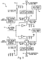
- a medium access controller antenna type select signal (MAC ATS signal) 52 is used to select the antenna type.
- the installer determines the type of antenna coverage required, rotates the antenna system to the desired position (vertical or horizontal) and then sets the antenna type using setup utility of the access point.
- the MAC controller then sets switches 54 based on the antenna type selected at installation. Normally, switches 54 would be semiconductor switches. The same antenna types are used as in the preferred embodiment, but the method of selection is different.
- either the access point or a user in the field could change the antenna type without being able to change antennas external to the AP itself.
- the MAC 52 will dynamically select either the left or the right antenna, based on system performance. OFDM systems are inherently robust against multipath conditions and packet-by-packet (or other) diversity algorithms are controlled by the MAC processor entirely on the radio board.
- the patch antennas may be mounted on a single RF circuit board or on a plurality of RF circuit boards.
- the near omni-directional antennas 46 could be external, captured antennas that are rotatably mounted so that they can always be positioned in an appropriate manner.
- the present invention may also be utilized in other fixed environments such as repeaters, or for mobile units being utilized as repeaters.
Landscapes
- Waveguide Aerials (AREA)
- Variable-Direction Aerials And Aerial Arrays (AREA)
- Radio Transmission System (AREA)
- Details Of Aerials (AREA)
Claims (12)
- Diversity-Antennensystem (40; 50) für einen Zugriffspunkt, mit:ersten und zweiten nahen Omnidirectional-Antennen (46), die ein erstes Diversity-Antennenpaar des Diversity-Antennensystems bilden;ersten und zweiten Innen-Patchantennen (20), die ein zweites Diversity-Antennenpaar des Diversity-Antennensystems bilden; undKonfigurationseinrichtungen (48; 52, 54), die so ausgelegt sind, dass sie, wobei sowohl das erste als auch das zweite Diversity-Antennenpaar an das Antennensystem gekoppelt ist, zum Zeitpunkt der Installation des Diversity-Antennensystems eine Auswahl entweder des ersten Diversity-Antennenpaars oder des zweiten Diversity-Antennenpaars ermöglichen, abhängig davon, wie der Zugriffspunkt angebracht ist, wobei die Konfigurationseinrichtungen einen mechanischen Erkennungsschalter (48) aufweisen, der so betreibbar ist, dass er den anzuwendenden Antennentyp bestimmt.
- Diversity-Antennensystem (40; 50) für einen Zugriffspunkt, mit:ersten und zweiten nahen Omnidirectional-Antennen (46), die ein erstes Diversity-Antennenpaar des Diversity-Antennensystems bilden;ersten und zweiten Innen-Patchantennen (20), die ein zweites Diversity-Antennenpaar des Diversity-Antennensystems bilden; undKonfigurationseinrichtungen (48; 52, 54), die so ausgelegt sind, dass sie, wobei sowohl das erste als auch das zweite Diversity-Antennenpaar an das Antennensystem gekoppelt ist, zum Zeitpunkt der Installation des Diversity-Antennensystems eine Auswahl entweder des ersten Diversity-Antennenpaars oder des zweiten Diversity-Antennenpaars ermöglichen, abhängig davon, wie der Zugriffspunkt angebracht ist, wobei die Konfigurationseinrichtungen einen Controller aufweisen, um ein Steuersignal (52) zum Schalten des Antennentyps bereitzustellen.
- Diversity-Antennensystem (40; 50) nach Anspruch 2, wobei der Controller ein Mikroprozessor ist, um das Steuersignal (52) bereitzustellen, wobei der Mikroprozessor veranlasst, dass computerlesbare Befehle auf einem computerlesbaren Medium gespeichert werden, wobei die computerlesbaren Befehle umfassen:computerlesbare Befehle zum Empfangen von Eingaben von einem Benutzer; undcomputerlesbare Befehle, die auf die Eingaben ansprechen, zum Auswählen der Art der Antenne basierend auf den Eingaben.
- Diversity-Antennensystem (40; 50) nach Anspruch 1, wobei der mechanische Erkennungsschalter (48) so betreibbar ist, dass er die Ausrichtung der Diversity-Antenne erkennt und die Antennenart basierend auf der Ausrichtung auswählt.
- Diversity-Antennensystem (40; 50) nach Anspruch 1, 2, 3 oder 4, wobei das Diversity-Antennensystem (40; 50) drehbar angebracht ist.
- Diversity-Antennensystem (40; 50) nach Anspruch 1, 2, 3 oder 4, wobei die Innen-Patenantennen (20) TM 10 - Modus Patchantennen aufweisen.
- Diversity-Antennensystem (40; 50) nach einem vorhergehenden Anspruch, wobei die nahen Omnidirectional-Antennen (46) und die Innen-Patchantennen (20) auf derselben Platine konstruiert sind.
- Diversity-Antennensystem (40; 50) nach Anspruch 1 oder 2, wobei das Diversity-Antennensystem für einen Zugriffspunkt ist, der in einem UNII - Band arbeitet, wobei das zweite Diversity-Paar TM 10 - Modus Antennen (20) aufweist, die auf einer Platine angebracht sind, die innerhalb des Zugriffspunkts anzubringen ist, und wobei die nahen Omnidirectional-Antennen des ersten Diversity-Paars so konfiguriert sind, dass sie extern, "gefangen" (captured) und drehbar angebracht sind.
- Diversity-Antennensystem (50) nach Anspruch 2, wobei das Diversity-Antennensystem für einen Zugriffspunkt ist, der in einem UNII - Band arbeitet, wobei das zweite Diversity-Paar TM 10 - Modus Patchantennen (20) aufweist, die auf einer Platine angebracht sind, die innerhalb des Zugriffspunkts anzubringen ist,
wobei die nahen Omnidirectional-Antennen des ersten Diversity-Paars so konfiguriert sind, dass sie extern, "gefangen" und drehbar angebracht sind, und
wobei die Konfigurationseinrichtungen einen Halbleiterschalter (54) aufweisen und der Controller ein Mikroprozessor ist, der veranlasst, dass computerlesbare Befehle auf einem computerlesbaren Medium gespeichert werden, wobei die computerlesbaren Befehle umfassen:computerlesbare Befehle zum Empfangen von Eingaben von einem Benutzer; undcomputerlesbare Befehle, die auf die Eingaben ansprechen, zum Auswählen der Art von Antenne basierend auf den Eingaben durch Bereitstellen des Steuersignals (52), um den Halbleiterschalter zu steuern. - Diversity-Antennensystem (40; 50) nach Anspruch 1, 8 oder 9, wobei das Diversity-Antennensystem für einen Zugriffspunkt ist, der so ausgelegt ist, dass er im 5150-5250 MHz - Band oder im 5250-5350 MHz - Band arbeitet.
- Diversity-Antennensystem (40; 50) nach Anspruch 2, wobei das Diversity-Antennensystem für einen Zugriffspunkt ist, der in einem UNII - Band arbeitet,
wobei das zweite Diversity-Paar TM 10 - Modus Patchantennen (20) aufweist, die auf einer Platine angebracht sind, die innerhalb des Zugriffspunkts anzubringen ist, wobei die nahen Omnidirectional-Antennen des ersten Diversity-Paars so konfiguriert sind, dass sie extern, "gefangen" und drehbar angeordnet sind, und wobei die Konfigurationseinrichtungen (52, 54) aufweisen:einen Halbleiterschalter (54) zum Schalten zwischen den nahen Omnidirectional-Antennen und den Patchantennen (46 und 20); undeine Verbindungseinrichtung, die so ausgelegt ist, dass sie die nahen Omnidirectional-Antennen und die Patchantennen (46 und 20) mit dem Halbleiterschalter verbindet;wobei das Steuersignal (52) so ausgelegt ist, dass es den Halbleiter zum Schalten veranlasst, um die Antennenart auszuwählen. - Drahtloser Zugriffspunkt, der das Diversity-Antennensystem eines vorhergehenden Anspruchs aufweist.
Applications Claiming Priority (3)
| Application Number | Priority Date | Filing Date | Title |
|---|---|---|---|
| US10/091,164 US6781544B2 (en) | 2002-03-04 | 2002-03-04 | Diversity antenna for UNII access point |
| US91164 | 2002-03-04 | ||
| PCT/US2003/006303 WO2003085776A1 (en) | 2002-03-04 | 2003-03-04 | Diversity antenna for unii access point |
Publications (2)
| Publication Number | Publication Date |
|---|---|
| EP1481441A1 EP1481441A1 (de) | 2004-12-01 |
| EP1481441B1 true EP1481441B1 (de) | 2008-06-11 |
Family
ID=28789727
Family Applications (1)
| Application Number | Title | Priority Date | Filing Date |
|---|---|---|---|
| EP03717925A Expired - Lifetime EP1481441B1 (de) | 2002-03-04 | 2003-03-04 | Diversityantenne für einen unii-zugangspunkt |
Country Status (8)
| Country | Link |
|---|---|
| US (1) | US6781544B2 (de) |
| EP (1) | EP1481441B1 (de) |
| CN (1) | CN100541909C (de) |
| AT (1) | ATE398344T1 (de) |
| AU (2) | AU2003222242B9 (de) |
| CA (1) | CA2478628C (de) |
| DE (1) | DE60321546D1 (de) |
| WO (1) | WO2003085776A1 (de) |
Cited By (1)
| Publication number | Priority date | Publication date | Assignee | Title |
|---|---|---|---|---|
| US12620701B2 (en) * | 2022-09-02 | 2026-05-05 | Hyundai Mobis Co., Ltd. | Switching antenna for automotive UWB communication |
Families Citing this family (78)
| Publication number | Priority date | Publication date | Assignee | Title |
|---|---|---|---|---|
| US6778844B2 (en) * | 2001-01-26 | 2004-08-17 | Dell Products L.P. | System for reducing multipath fade of RF signals in a wireless data application |
| JP2005531202A (ja) | 2002-06-21 | 2005-10-13 | ワイデファイ インコーポレイテッド | 無線ローカル・エリア・ネットワーク・リピータ |
| US8885688B2 (en) | 2002-10-01 | 2014-11-11 | Qualcomm Incorporated | Control message management in physical layer repeater |
| KR101012629B1 (ko) | 2002-10-11 | 2011-02-09 | 퀄컴 인코포레이티드 | Wlan 중계기 내에서의 루프 효과의 감소 방법 |
| BR0315372A (pt) | 2002-10-15 | 2005-08-23 | Widefi Inc | Repetidor de translação de frequência, e, método para translação de frequência |
| US8078100B2 (en) | 2002-10-15 | 2011-12-13 | Qualcomm Incorporated | Physical layer repeater with discrete time filter for all-digital detection and delay generation |
| US7230935B2 (en) | 2002-10-24 | 2007-06-12 | Widefi, Inc. | Physical layer repeater with selective use of higher layer functions based on network operating conditions |
| JP3920196B2 (ja) * | 2002-11-11 | 2007-05-30 | 松下電器産業株式会社 | 携帯無線装置 |
| BR0316218A (pt) | 2002-11-15 | 2005-09-27 | Widefi Inc | Método e aparelho para detectar a presença de um sinal em um de pelo menos dois canais de frequência em um repetidor de translação de frequência para uso em uma rede de área local sem fios (wlan) |
| JP2004180038A (ja) * | 2002-11-28 | 2004-06-24 | Nec Infrontia Corp | 無線lanアクセスポイント,無線lanシステム,無線lanアクセスポイントの干渉防止方法 |
| AU2003300938A1 (en) | 2002-12-16 | 2004-07-29 | Widefi, Inc. | Improved wireless network repeater |
| ATE328400T1 (de) * | 2003-03-19 | 2006-06-15 | Sony Ericsson Mobile Comm Ab | Schaltbare antennenanordnung |
| US6924766B2 (en) * | 2003-04-03 | 2005-08-02 | Kyocera Wireless Corp. | Wireless telephone antenna diversity system |
| US20050186991A1 (en) * | 2004-02-10 | 2005-08-25 | Bateman Blaine R. | Wireless access point with enhanced coverage |
| US7499673B2 (en) * | 2004-03-23 | 2009-03-03 | Cisco Technology, Inc. | Configurable diversity antenna system for wireless access points |
| US8027642B2 (en) | 2004-04-06 | 2011-09-27 | Qualcomm Incorporated | Transmission canceller for wireless local area network |
| CN1993904B (zh) | 2004-05-13 | 2011-09-07 | 高通股份有限公司 | 具有用于上行链路及下行链路同步之下行链路检测的非变频中继器 |
| US7187904B2 (en) | 2004-06-03 | 2007-03-06 | Widefi, Inc. | Frequency translating repeater with low cost high performance local oscillator architecture |
| US8031129B2 (en) | 2004-08-18 | 2011-10-04 | Ruckus Wireless, Inc. | Dual band dual polarization antenna array |
| US7899497B2 (en) | 2004-08-18 | 2011-03-01 | Ruckus Wireless, Inc. | System and method for transmission parameter control for an antenna apparatus with selectable elements |
| US7362280B2 (en) | 2004-08-18 | 2008-04-22 | Ruckus Wireless, Inc. | System and method for a minimized antenna apparatus with selectable elements |
| US7652632B2 (en) | 2004-08-18 | 2010-01-26 | Ruckus Wireless, Inc. | Multiband omnidirectional planar antenna apparatus with selectable elements |
| US7292198B2 (en) | 2004-08-18 | 2007-11-06 | Ruckus Wireless, Inc. | System and method for an omnidirectional planar antenna apparatus with selectable elements |
| US7880683B2 (en) | 2004-08-18 | 2011-02-01 | Ruckus Wireless, Inc. | Antennas with polarization diversity |
| US7498996B2 (en) | 2004-08-18 | 2009-03-03 | Ruckus Wireless, Inc. | Antennas with polarization diversity |
| US7696946B2 (en) | 2004-08-18 | 2010-04-13 | Ruckus Wireless, Inc. | Reducing stray capacitance in antenna element switching |
| US7965252B2 (en) | 2004-08-18 | 2011-06-21 | Ruckus Wireless, Inc. | Dual polarization antenna array with increased wireless coverage |
| US7193562B2 (en) | 2004-11-22 | 2007-03-20 | Ruckus Wireless, Inc. | Circuit board having a peripheral antenna apparatus with selectable antenna elements |
| US7933628B2 (en) | 2004-08-18 | 2011-04-26 | Ruckus Wireless, Inc. | Transmission and reception parameter control |
| US7505447B2 (en) | 2004-11-05 | 2009-03-17 | Ruckus Wireless, Inc. | Systems and methods for improved data throughput in communications networks |
| TWI391018B (zh) | 2004-11-05 | 2013-03-21 | Ruckus Wireless Inc | 藉由確認抑制之增強資訊量 |
| US8619662B2 (en) | 2004-11-05 | 2013-12-31 | Ruckus Wireless, Inc. | Unicast to multicast conversion |
| US8638708B2 (en) | 2004-11-05 | 2014-01-28 | Ruckus Wireless, Inc. | MAC based mapping in IP based communications |
| CN1934750B (zh) | 2004-11-22 | 2012-07-18 | 鲁库斯无线公司 | 包括具有可选择天线元件的外围天线装置的电路板 |
| US7358912B1 (en) | 2005-06-24 | 2008-04-15 | Ruckus Wireless, Inc. | Coverage antenna apparatus with selectable horizontal and vertical polarization elements |
| US8792414B2 (en) | 2005-07-26 | 2014-07-29 | Ruckus Wireless, Inc. | Coverage enhancement using dynamic antennas |
| US7893882B2 (en) | 2007-01-08 | 2011-02-22 | Ruckus Wireless, Inc. | Pattern shaping of RF emission patterns |
| US7646343B2 (en) | 2005-06-24 | 2010-01-12 | Ruckus Wireless, Inc. | Multiple-input multiple-output wireless antennas |
| WO2006081405A2 (en) | 2005-01-28 | 2006-08-03 | Widefi, Inc. | Physical layer repeater configuration for increasing mino performance |
| US7576655B2 (en) * | 2005-03-29 | 2009-08-18 | Accu-Sort Systems, Inc. | RFID conveyor system and method |
| US7603141B2 (en) * | 2005-06-02 | 2009-10-13 | Qualcomm, Inc. | Multi-antenna station with distributed antennas |
| JP4676296B2 (ja) * | 2005-10-05 | 2011-04-27 | 東芝テック株式会社 | 漏洩伝送路ダイバーシティ装置 |
| US7333068B2 (en) | 2005-11-15 | 2008-02-19 | Clearone Communications, Inc. | Planar anti-reflective interference antennas with extra-planar element extensions |
| US7446714B2 (en) | 2005-11-15 | 2008-11-04 | Clearone Communications, Inc. | Anti-reflective interference antennas with radially-oriented elements |
| US7480502B2 (en) | 2005-11-15 | 2009-01-20 | Clearone Communications, Inc. | Wireless communications device with reflective interference immunity |
| KR20080078692A (ko) * | 2005-11-22 | 2008-08-27 | 퀄컴 인코포레이티드 | Tdd 중계기용 방향성 안테나 구성 |
| WO2007064822A2 (en) | 2005-12-01 | 2007-06-07 | Ruckus Wireless, Inc. | On-demand services by wireless base station virtualization |
| US9769655B2 (en) | 2006-04-24 | 2017-09-19 | Ruckus Wireless, Inc. | Sharing security keys with headless devices |
| WO2007127120A2 (en) | 2006-04-24 | 2007-11-08 | Ruckus Wireless, Inc. | Dynamic authentication in secured wireless networks |
| US9071583B2 (en) | 2006-04-24 | 2015-06-30 | Ruckus Wireless, Inc. | Provisioned configuration for automatic wireless connection |
| US7639106B2 (en) | 2006-04-28 | 2009-12-29 | Ruckus Wireless, Inc. | PIN diode network for multiband RF coupling |
| US8670725B2 (en) | 2006-08-18 | 2014-03-11 | Ruckus Wireless, Inc. | Closed-loop automatic channel selection |
| KR101123600B1 (ko) | 2006-09-21 | 2012-03-21 | 퀄컴 인코포레이티드 | 중계기들 사이에서 발진을 완화시키는 방법 및 장치 |
| WO2008057290A1 (en) | 2006-10-26 | 2008-05-15 | Qualcomm Incorporated | Repeater techniques for multiple input multiple output utilizing beam formers |
| KR101301418B1 (ko) * | 2006-10-31 | 2013-08-28 | 퀄컴 인코포레이티드 | 센서-기반 무선 수신 다이버시티를 위한 장치 및 방법 |
| US20100330940A1 (en) * | 2006-10-31 | 2010-12-30 | Qualcomm Incorporated | Sensor-aided wireless combining |
| US8547899B2 (en) | 2007-07-28 | 2013-10-01 | Ruckus Wireless, Inc. | Wireless network throughput enhancement through channel aware scheduling |
| US9848058B2 (en) | 2007-08-31 | 2017-12-19 | Cardiac Pacemakers, Inc. | Medical data transport over wireless life critical network employing dynamic communication link mapping |
| US7978062B2 (en) | 2007-08-31 | 2011-07-12 | Cardiac Pacemakers, Inc. | Medical data transport over wireless life critical network |
| US8355343B2 (en) | 2008-01-11 | 2013-01-15 | Ruckus Wireless, Inc. | Determining associations in a mesh network |
| US8812841B2 (en) | 2009-03-04 | 2014-08-19 | Cardiac Pacemakers, Inc. | Communications hub for use in life critical network |
| US8319631B2 (en) | 2009-03-04 | 2012-11-27 | Cardiac Pacemakers, Inc. | Modular patient portable communicator for use in life critical network |
| US8217843B2 (en) | 2009-03-13 | 2012-07-10 | Ruckus Wireless, Inc. | Adjustment of radiation patterns utilizing a position sensor |
| US8698675B2 (en) | 2009-05-12 | 2014-04-15 | Ruckus Wireless, Inc. | Mountable antenna elements for dual band antenna |
| US9999087B2 (en) | 2009-11-16 | 2018-06-12 | Ruckus Wireless, Inc. | Determining role assignment in a hybrid mesh network |
| US9979626B2 (en) | 2009-11-16 | 2018-05-22 | Ruckus Wireless, Inc. | Establishing a mesh network with wired and wireless links |
| CN101895011B (zh) * | 2010-06-13 | 2013-04-10 | 南京邮电大学 | 对称振子-对跖槽线组合结构的宽带印刷天线 |
| CN101895009B (zh) * | 2010-06-13 | 2013-06-05 | 南京邮电大学 | 对称振子-渐变槽线组合结构的双频宽带天线 |
| US9407012B2 (en) | 2010-09-21 | 2016-08-02 | Ruckus Wireless, Inc. | Antenna with dual polarization and mountable antenna elements |
| EP2705429B1 (de) | 2011-05-01 | 2016-07-06 | Ruckus Wireless, Inc. | Fernzurücksetzung eines kabelzugangspunktes |
| US8756668B2 (en) | 2012-02-09 | 2014-06-17 | Ruckus Wireless, Inc. | Dynamic PSK for hotspots |
| US9634403B2 (en) | 2012-02-14 | 2017-04-25 | Ruckus Wireless, Inc. | Radio frequency emission pattern shaping |
| US10186750B2 (en) | 2012-02-14 | 2019-01-22 | Arris Enterprises Llc | Radio frequency antenna array with spacing element |
| US9092610B2 (en) | 2012-04-04 | 2015-07-28 | Ruckus Wireless, Inc. | Key assignment for a brand |
| US9570799B2 (en) | 2012-09-07 | 2017-02-14 | Ruckus Wireless, Inc. | Multiband monopole antenna apparatus with ground plane aperture |
| EP2974045A4 (de) | 2013-03-15 | 2016-11-09 | Ruckus Wireless Inc | Niedrigbandreflektor für eine gerichtete doppelbandantenne |
| US12088013B2 (en) | 2021-03-30 | 2024-09-10 | Skyworks Solutions, Inc. | Frequency range two antenna array with switches for joining antennas for frequency range one communications |
| US20250212011A1 (en) * | 2023-12-20 | 2025-06-26 | Cisco Technology, Inc. | Pattern and receive diversity in ultra-wideband radio systems |
Family Cites Families (17)
| Publication number | Priority date | Publication date | Assignee | Title |
|---|---|---|---|---|
| US5594455A (en) * | 1994-06-13 | 1997-01-14 | Nippon Telegraph & Telephone Corporation | Bidirectional printed antenna |
| US5649306A (en) * | 1994-09-16 | 1997-07-15 | Motorola, Inc. | Portable radio housing incorporating diversity antenna structure |
| CN1225784A (zh) * | 1996-06-28 | 1999-08-11 | 哈里公司 | 无线通信系统和具有多方向天线的转接交换机 |
| US6094166A (en) * | 1996-07-16 | 2000-07-25 | Metawave Communications Corporation | Conical omni-directional coverage multibeam antenna with parasitic elements |
| JP3204111B2 (ja) | 1996-08-28 | 2001-09-04 | 松下電器産業株式会社 | 指向性制御アンテナ装置 |
| GB2317993A (en) | 1996-10-02 | 1998-04-08 | Ico Services Ltd | Antenna switching means for portable radio apparatus |
| GB9626550D0 (en) | 1996-12-20 | 1997-02-05 | Northern Telecom Ltd | A dipole antenna |
| US5952922A (en) * | 1996-12-31 | 1999-09-14 | Lucent Technologies Inc. | In-building modulated backscatter system |
| US6031503A (en) | 1997-02-20 | 2000-02-29 | Raytheon Company | Polarization diverse antenna for portable communication devices |
| US6108526A (en) | 1997-05-07 | 2000-08-22 | Lucent Technologies, Inc. | Antenna system and method thereof |
| EP0877443B1 (de) | 1997-05-09 | 2008-01-02 | Nippon Telegraph And Telephone Corporation | Antenne und Verfahren zu ihrer Herstellung |
| FR2779022B1 (fr) | 1998-05-20 | 2000-07-28 | Nortel Matra Cellular | Station de base de radiocommunication |
| US6264152B1 (en) | 1998-07-17 | 2001-07-24 | Lucent Technologies Inc. | Multiple access mounting bracket |
| US6240301B1 (en) | 1998-10-29 | 2001-05-29 | Ericcson Inc. | Diversity antenna in a SIM card package |
| US7577398B2 (en) * | 2000-01-14 | 2009-08-18 | Andrew Llc | Repeaters for wireless communication systems |
| WO2001013461A1 (en) * | 1999-08-13 | 2001-02-22 | Rangestar Wireless, Inc. | Diversity antenna system for lan communication system |
| FI114592B (fi) * | 2000-06-30 | 2004-11-15 | Nokia Corp | Kytkin- ja liitinjärjestely ulkoisten ja sisäisten antennien kytkemiseksi esimerkiksi laajennuskorttiin |
-
2002
- 2002-03-04 US US10/091,164 patent/US6781544B2/en not_active Expired - Lifetime
-
2003
- 2003-03-04 WO PCT/US2003/006303 patent/WO2003085776A1/en not_active Ceased
- 2003-03-04 EP EP03717925A patent/EP1481441B1/de not_active Expired - Lifetime
- 2003-03-04 CN CNB038053586A patent/CN100541909C/zh not_active Expired - Fee Related
- 2003-03-04 AT AT03717925T patent/ATE398344T1/de not_active IP Right Cessation
- 2003-03-04 DE DE60321546T patent/DE60321546D1/de not_active Expired - Lifetime
- 2003-03-04 CA CA002478628A patent/CA2478628C/en not_active Expired - Fee Related
- 2003-03-04 AU AU2003222242A patent/AU2003222242B9/en not_active Ceased
-
2008
- 2008-08-25 AU AU2008207489A patent/AU2008207489A1/en not_active Abandoned
Cited By (1)
| Publication number | Priority date | Publication date | Assignee | Title |
|---|---|---|---|---|
| US12620701B2 (en) * | 2022-09-02 | 2026-05-05 | Hyundai Mobis Co., Ltd. | Switching antenna for automotive UWB communication |
Also Published As
| Publication number | Publication date |
|---|---|
| WO2003085776A1 (en) | 2003-10-16 |
| CA2478628A1 (en) | 2003-10-16 |
| ATE398344T1 (de) | 2008-07-15 |
| CN100541909C (zh) | 2009-09-16 |
| AU2008207489A1 (en) | 2008-09-11 |
| AU2003222242B9 (en) | 2008-10-23 |
| AU2003222242B2 (en) | 2008-09-04 |
| US6781544B2 (en) | 2004-08-24 |
| DE60321546D1 (de) | 2008-07-24 |
| EP1481441A1 (de) | 2004-12-01 |
| AU2003222242A1 (en) | 2003-10-20 |
| US20030227414A1 (en) | 2003-12-11 |
| CN1639906A (zh) | 2005-07-13 |
| CA2478628C (en) | 2009-09-01 |
Similar Documents
| Publication | Publication Date | Title |
|---|---|---|
| US6781544B2 (en) | Diversity antenna for UNII access point | |
| EP0936693B1 (de) | Antennen-Tragstruktur | |
| US9729213B2 (en) | MIMO antenna system | |
| EP1782499B1 (de) | System und verfahren für eine omnidirektionale planarantennenvorrichtung mit wählbaren elementen | |
| US7057566B2 (en) | Flexible multichannel WLAN access point architecture | |
| US9564689B2 (en) | MIMO antenna system | |
| US20040046694A1 (en) | Mobile communication handset with adaptive antenna array | |
| US20060038735A1 (en) | System and method for a minimized antenna apparatus with selectable elements | |
| KR20070058009A (ko) | 비동조 배열 안테나 | |
| KR20070058005A (ko) | 다중 패턴 안테나 | |
| JP2005520383A (ja) | 適応受信および無指向性送信のアンテナ・アレイ | |
| WO2012004602A1 (en) | Antenna assembly for a wireless communications device | |
| EP1733484B1 (de) | Konfigurierbares diversity-antennensystem für drahtlose zugangspunkte | |
| US6693603B1 (en) | Communications antenna structure | |
| WO2018037278A2 (zh) | 天线及其制造方法 | |
| CA3151711C (en) | Beam diversity by smart antenna with passive elements | |
| JP2000151254A (ja) | セクタアンテナ装置 | |
| KR20230046175A (ko) | 전력을 조절하기 위한 전자 장치 및 그 동작 방법 | |
| Uno et al. | A planar sector antenna suitable for small WLAN card terminal | |
| WO2002031919A1 (en) | Antenna array | |
| HK1180836B (en) | Multiband omnidirectional planar antenna apparatus with selectable elements | |
| CA2565032A1 (en) | A reconfigurable mimo antenna system for ieee 802.11n systems |
Legal Events
| Date | Code | Title | Description |
|---|---|---|---|
| PUAI | Public reference made under article 153(3) epc to a published international application that has entered the european phase |
Free format text: ORIGINAL CODE: 0009012 |
|
| 17P | Request for examination filed |
Effective date: 20040914 |
|
| AK | Designated contracting states |
Kind code of ref document: A1 Designated state(s): AT BE BG CH CY CZ DE DK EE ES FI FR GB GR HU IE IT LI LU MC NL PT RO SE SI SK TR |
|
| AX | Request for extension of the european patent |
Extension state: AL LT LV MK |
|
| RIN1 | Information on inventor provided before grant (corrected) |
Inventor name: FRANK, TIMOTHY Inventor name: MASS, JAMES Inventor name: ANDERSON, FRED Inventor name: SALIGA, STEPHEN |
|
| 17Q | First examination report despatched |
Effective date: 20070402 |
|
| GRAP | Despatch of communication of intention to grant a patent |
Free format text: ORIGINAL CODE: EPIDOSNIGR1 |
|
| GRAS | Grant fee paid |
Free format text: ORIGINAL CODE: EPIDOSNIGR3 |
|
| GRAA | (expected) grant |
Free format text: ORIGINAL CODE: 0009210 |
|
| AK | Designated contracting states |
Kind code of ref document: B1 Designated state(s): AT BE BG CH CY CZ DE DK EE ES FI FR GB GR HU IE IT LI LU MC NL PT RO SE SI SK TR |
|
| REG | Reference to a national code |
Ref country code: GB Ref legal event code: FG4D |
|
| REG | Reference to a national code |
Ref country code: CH Ref legal event code: EP |
|
| REF | Corresponds to: |
Ref document number: 60321546 Country of ref document: DE Date of ref document: 20080724 Kind code of ref document: P |
|
| REG | Reference to a national code |
Ref country code: IE Ref legal event code: FG4D |
|
| PG25 | Lapsed in a contracting state [announced via postgrant information from national office to epo] |
Ref country code: SI Free format text: LAPSE BECAUSE OF FAILURE TO SUBMIT A TRANSLATION OF THE DESCRIPTION OR TO PAY THE FEE WITHIN THE PRESCRIBED TIME-LIMIT Effective date: 20080611 |
|
| PG25 | Lapsed in a contracting state [announced via postgrant information from national office to epo] |
Ref country code: NL Free format text: LAPSE BECAUSE OF FAILURE TO SUBMIT A TRANSLATION OF THE DESCRIPTION OR TO PAY THE FEE WITHIN THE PRESCRIBED TIME-LIMIT Effective date: 20080611 Ref country code: AT Free format text: LAPSE BECAUSE OF FAILURE TO SUBMIT A TRANSLATION OF THE DESCRIPTION OR TO PAY THE FEE WITHIN THE PRESCRIBED TIME-LIMIT Effective date: 20080611 |
|
| NLV1 | Nl: lapsed or annulled due to failure to fulfill the requirements of art. 29p and 29m of the patents act | ||
| PG25 | Lapsed in a contracting state [announced via postgrant information from national office to epo] |
Ref country code: PT Free format text: LAPSE BECAUSE OF FAILURE TO SUBMIT A TRANSLATION OF THE DESCRIPTION OR TO PAY THE FEE WITHIN THE PRESCRIBED TIME-LIMIT Effective date: 20081111 Ref country code: ES Free format text: LAPSE BECAUSE OF FAILURE TO SUBMIT A TRANSLATION OF THE DESCRIPTION OR TO PAY THE FEE WITHIN THE PRESCRIBED TIME-LIMIT Effective date: 20080922 Ref country code: CZ Free format text: LAPSE BECAUSE OF FAILURE TO SUBMIT A TRANSLATION OF THE DESCRIPTION OR TO PAY THE FEE WITHIN THE PRESCRIBED TIME-LIMIT Effective date: 20080611 Ref country code: SE Free format text: LAPSE BECAUSE OF FAILURE TO SUBMIT A TRANSLATION OF THE DESCRIPTION OR TO PAY THE FEE WITHIN THE PRESCRIBED TIME-LIMIT Effective date: 20080911 |
|
| PG25 | Lapsed in a contracting state [announced via postgrant information from national office to epo] |
Ref country code: SK Free format text: LAPSE BECAUSE OF FAILURE TO SUBMIT A TRANSLATION OF THE DESCRIPTION OR TO PAY THE FEE WITHIN THE PRESCRIBED TIME-LIMIT Effective date: 20080611 Ref country code: RO Free format text: LAPSE BECAUSE OF FAILURE TO SUBMIT A TRANSLATION OF THE DESCRIPTION OR TO PAY THE FEE WITHIN THE PRESCRIBED TIME-LIMIT Effective date: 20080611 Ref country code: BE Free format text: LAPSE BECAUSE OF FAILURE TO SUBMIT A TRANSLATION OF THE DESCRIPTION OR TO PAY THE FEE WITHIN THE PRESCRIBED TIME-LIMIT Effective date: 20080611 |
|
| PLBE | No opposition filed within time limit |
Free format text: ORIGINAL CODE: 0009261 |
|
| STAA | Information on the status of an ep patent application or granted ep patent |
Free format text: STATUS: NO OPPOSITION FILED WITHIN TIME LIMIT |
|
| PG25 | Lapsed in a contracting state [announced via postgrant information from national office to epo] |
Ref country code: EE Free format text: LAPSE BECAUSE OF FAILURE TO SUBMIT A TRANSLATION OF THE DESCRIPTION OR TO PAY THE FEE WITHIN THE PRESCRIBED TIME-LIMIT Effective date: 20080611 Ref country code: DK Free format text: LAPSE BECAUSE OF FAILURE TO SUBMIT A TRANSLATION OF THE DESCRIPTION OR TO PAY THE FEE WITHIN THE PRESCRIBED TIME-LIMIT Effective date: 20080611 Ref country code: BG Free format text: LAPSE BECAUSE OF FAILURE TO SUBMIT A TRANSLATION OF THE DESCRIPTION OR TO PAY THE FEE WITHIN THE PRESCRIBED TIME-LIMIT Effective date: 20080911 |
|
| 26N | No opposition filed |
Effective date: 20090312 |
|
| PG25 | Lapsed in a contracting state [announced via postgrant information from national office to epo] |
Ref country code: IT Free format text: LAPSE BECAUSE OF FAILURE TO SUBMIT A TRANSLATION OF THE DESCRIPTION OR TO PAY THE FEE WITHIN THE PRESCRIBED TIME-LIMIT Effective date: 20080611 |
|
| PG25 | Lapsed in a contracting state [announced via postgrant information from national office to epo] |
Ref country code: MC Free format text: LAPSE BECAUSE OF NON-PAYMENT OF DUE FEES Effective date: 20090331 |
|
| REG | Reference to a national code |
Ref country code: CH Ref legal event code: PL |
|
| REG | Reference to a national code |
Ref country code: IE Ref legal event code: MM4A |
|
| PG25 | Lapsed in a contracting state [announced via postgrant information from national office to epo] |
Ref country code: LI Free format text: LAPSE BECAUSE OF NON-PAYMENT OF DUE FEES Effective date: 20090331 Ref country code: IE Free format text: LAPSE BECAUSE OF NON-PAYMENT OF DUE FEES Effective date: 20090304 Ref country code: CH Free format text: LAPSE BECAUSE OF NON-PAYMENT OF DUE FEES Effective date: 20090331 |
|
| PG25 | Lapsed in a contracting state [announced via postgrant information from national office to epo] |
Ref country code: GR Free format text: LAPSE BECAUSE OF FAILURE TO SUBMIT A TRANSLATION OF THE DESCRIPTION OR TO PAY THE FEE WITHIN THE PRESCRIBED TIME-LIMIT Effective date: 20080912 |
|
| PG25 | Lapsed in a contracting state [announced via postgrant information from national office to epo] |
Ref country code: LU Free format text: LAPSE BECAUSE OF NON-PAYMENT OF DUE FEES Effective date: 20090304 |
|
| PG25 | Lapsed in a contracting state [announced via postgrant information from national office to epo] |
Ref country code: HU Free format text: LAPSE BECAUSE OF FAILURE TO SUBMIT A TRANSLATION OF THE DESCRIPTION OR TO PAY THE FEE WITHIN THE PRESCRIBED TIME-LIMIT Effective date: 20081212 |
|
| PG25 | Lapsed in a contracting state [announced via postgrant information from national office to epo] |
Ref country code: TR Free format text: LAPSE BECAUSE OF FAILURE TO SUBMIT A TRANSLATION OF THE DESCRIPTION OR TO PAY THE FEE WITHIN THE PRESCRIBED TIME-LIMIT Effective date: 20080611 |
|
| PG25 | Lapsed in a contracting state [announced via postgrant information from national office to epo] |
Ref country code: CY Free format text: LAPSE BECAUSE OF FAILURE TO SUBMIT A TRANSLATION OF THE DESCRIPTION OR TO PAY THE FEE WITHIN THE PRESCRIBED TIME-LIMIT Effective date: 20080611 |
|
| REG | Reference to a national code |
Ref country code: FR Ref legal event code: PLFP Year of fee payment: 13 |
|
| REG | Reference to a national code |
Ref country code: FR Ref legal event code: PLFP Year of fee payment: 14 |
|
| PGFP | Annual fee paid to national office [announced via postgrant information from national office to epo] |
Ref country code: FI Payment date: 20160325 Year of fee payment: 14 |
|
| REG | Reference to a national code |
Ref country code: FR Ref legal event code: PLFP Year of fee payment: 15 |
|
| PG25 | Lapsed in a contracting state [announced via postgrant information from national office to epo] |
Ref country code: FI Free format text: LAPSE BECAUSE OF NON-PAYMENT OF DUE FEES Effective date: 20170304 |
|
| REG | Reference to a national code |
Ref country code: FR Ref legal event code: PLFP Year of fee payment: 16 |
|
| PGFP | Annual fee paid to national office [announced via postgrant information from national office to epo] |
Ref country code: DE Payment date: 20200327 Year of fee payment: 18 Ref country code: GB Payment date: 20200327 Year of fee payment: 18 |
|
| PGFP | Annual fee paid to national office [announced via postgrant information from national office to epo] |
Ref country code: FR Payment date: 20200325 Year of fee payment: 18 |
|
| REG | Reference to a national code |
Ref country code: DE Ref legal event code: R119 Ref document number: 60321546 Country of ref document: DE |
|
| GBPC | Gb: european patent ceased through non-payment of renewal fee |
Effective date: 20210304 |
|
| PG25 | Lapsed in a contracting state [announced via postgrant information from national office to epo] |
Ref country code: DE Free format text: LAPSE BECAUSE OF NON-PAYMENT OF DUE FEES Effective date: 20211001 Ref country code: FR Free format text: LAPSE BECAUSE OF NON-PAYMENT OF DUE FEES Effective date: 20210331 Ref country code: GB Free format text: LAPSE BECAUSE OF NON-PAYMENT OF DUE FEES Effective date: 20210304 |
|
| P01 | Opt-out of the competence of the unified patent court (upc) registered |
Effective date: 20230525 |