EP1481637B1 - Système d'étalonnage pour un cathéter d'ultrason - Google Patents
Système d'étalonnage pour un cathéter d'ultrason Download PDFInfo
- Publication number
- EP1481637B1 EP1481637B1 EP04253230A EP04253230A EP1481637B1 EP 1481637 B1 EP1481637 B1 EP 1481637B1 EP 04253230 A EP04253230 A EP 04253230A EP 04253230 A EP04253230 A EP 04253230A EP 1481637 B1 EP1481637 B1 EP 1481637B1
- Authority
- EP
- European Patent Office
- Prior art keywords
- probe
- calibration data
- orientation
- alignment
- sensor
- Prior art date
- Legal status (The legal status is an assumption and is not a legal conclusion. Google has not performed a legal analysis and makes no representation as to the accuracy of the status listed.)
- Expired - Lifetime
Links
- 238000002604 ultrasonography Methods 0.000 title claims description 38
- 239000000523 sample Substances 0.000 claims description 152
- 238000000034 method Methods 0.000 claims description 59
- 238000012360 testing method Methods 0.000 claims description 44
- 238000003384 imaging method Methods 0.000 claims description 37
- 238000006073 displacement reaction Methods 0.000 claims description 16
- 239000000463 material Substances 0.000 claims description 6
- 238000010438 heat treatment Methods 0.000 claims description 5
- 230000003213 activating effect Effects 0.000 claims description 3
- 238000001816 cooling Methods 0.000 claims description 2
- 230000001419 dependent effect Effects 0.000 claims 1
- 230000005855 radiation Effects 0.000 description 5
- 238000001574 biopsy Methods 0.000 description 4
- 230000008859 change Effects 0.000 description 4
- 238000004519 manufacturing process Methods 0.000 description 4
- 238000005259 measurement Methods 0.000 description 4
- 230000004044 response Effects 0.000 description 4
- 238000010606 normalization Methods 0.000 description 3
- 238000012545 processing Methods 0.000 description 3
- 230000001225 therapeutic effect Effects 0.000 description 3
- 238000012937 correction Methods 0.000 description 2
- 238000002675 image-guided surgery Methods 0.000 description 2
- 238000003780 insertion Methods 0.000 description 2
- 230000037431 insertion Effects 0.000 description 2
- 230000008569 process Effects 0.000 description 2
- 238000012285 ultrasound imaging Methods 0.000 description 2
- 230000005355 Hall effect Effects 0.000 description 1
- 238000003745 diagnosis Methods 0.000 description 1
- 230000005672 electromagnetic field Effects 0.000 description 1
- 230000002631 hypothermal effect Effects 0.000 description 1
- 238000010348 incorporation Methods 0.000 description 1
- 230000001939 inductive effect Effects 0.000 description 1
- 230000013011 mating Effects 0.000 description 1
- 238000012986 modification Methods 0.000 description 1
- 230000004048 modification Effects 0.000 description 1
- 238000001356 surgical procedure Methods 0.000 description 1
- 238000004804 winding Methods 0.000 description 1
- 229910000859 α-Fe Inorganic materials 0.000 description 1
Images


Classifications
-
- A—HUMAN NECESSITIES
- A61—MEDICAL OR VETERINARY SCIENCE; HYGIENE
- A61B—DIAGNOSIS; SURGERY; IDENTIFICATION
- A61B8/00—Diagnosis using ultrasonic, sonic or infrasonic waves
- A61B8/58—Testing, adjusting or calibrating the diagnostic device
-
- A—HUMAN NECESSITIES
- A61—MEDICAL OR VETERINARY SCIENCE; HYGIENE
- A61B—DIAGNOSIS; SURGERY; IDENTIFICATION
- A61B34/00—Computer-aided surgery; Manipulators or robots specially adapted for use in surgery
- A61B34/20—Surgical navigation systems; Devices for tracking or guiding surgical instruments, e.g. for frameless stereotaxis
-
- A—HUMAN NECESSITIES
- A61—MEDICAL OR VETERINARY SCIENCE; HYGIENE
- A61B—DIAGNOSIS; SURGERY; IDENTIFICATION
- A61B5/00—Measuring for diagnostic purposes; Identification of persons
- A61B5/06—Devices, other than using radiation, for detecting or locating foreign bodies ; Determining position of diagnostic devices within or on the body of the patient
- A61B5/061—Determining position of a probe within the body employing means separate from the probe, e.g. sensing internal probe position employing impedance electrodes on the surface of the body
- A61B5/062—Determining position of a probe within the body employing means separate from the probe, e.g. sensing internal probe position employing impedance electrodes on the surface of the body using magnetic field
-
- A—HUMAN NECESSITIES
- A61—MEDICAL OR VETERINARY SCIENCE; HYGIENE
- A61B—DIAGNOSIS; SURGERY; IDENTIFICATION
- A61B8/00—Diagnosis using ultrasonic, sonic or infrasonic waves
- A61B8/12—Diagnosis using ultrasonic, sonic or infrasonic waves in body cavities or body tracts, e.g. by using catheters
-
- A—HUMAN NECESSITIES
- A61—MEDICAL OR VETERINARY SCIENCE; HYGIENE
- A61B—DIAGNOSIS; SURGERY; IDENTIFICATION
- A61B8/00—Diagnosis using ultrasonic, sonic or infrasonic waves
- A61B8/42—Details of probe positioning or probe attachment to the patient
- A61B8/4245—Details of probe positioning or probe attachment to the patient involving determining the position of the probe, e.g. with respect to an external reference frame or to the patient
- A61B8/4254—Details of probe positioning or probe attachment to the patient involving determining the position of the probe, e.g. with respect to an external reference frame or to the patient using sensors mounted on the probe
-
- A—HUMAN NECESSITIES
- A61—MEDICAL OR VETERINARY SCIENCE; HYGIENE
- A61B—DIAGNOSIS; SURGERY; IDENTIFICATION
- A61B17/00—Surgical instruments, devices or methods
- A61B2017/00681—Aspects not otherwise provided for
- A61B2017/00725—Calibration or performance testing
-
- A—HUMAN NECESSITIES
- A61—MEDICAL OR VETERINARY SCIENCE; HYGIENE
- A61B—DIAGNOSIS; SURGERY; IDENTIFICATION
- A61B34/00—Computer-aided surgery; Manipulators or robots specially adapted for use in surgery
- A61B34/20—Surgical navigation systems; Devices for tracking or guiding surgical instruments, e.g. for frameless stereotaxis
- A61B2034/2046—Tracking techniques
- A61B2034/2051—Electromagnetic tracking systems
-
- A—HUMAN NECESSITIES
- A61—MEDICAL OR VETERINARY SCIENCE; HYGIENE
- A61B—DIAGNOSIS; SURGERY; IDENTIFICATION
- A61B90/00—Instruments, implements or accessories specially adapted for surgery or diagnosis and not covered by any of the groups A61B1/00 - A61B50/00, e.g. for luxation treatment or for protecting wound edges
- A61B90/36—Image-producing devices or illumination devices not otherwise provided for
- A61B90/37—Surgical systems with images on a monitor during operation
- A61B2090/378—Surgical systems with images on a monitor during operation using ultrasound
- A61B2090/3782—Surgical systems with images on a monitor during operation using ultrasound transmitter or receiver in catheter or minimal invasive instrument
- A61B2090/3784—Surgical systems with images on a monitor during operation using ultrasound transmitter or receiver in catheter or minimal invasive instrument both receiver and transmitter being in the instrument or receiver being also transmitter
-
- H—ELECTRICITY
- H01—ELECTRIC ELEMENTS
- H01F—MAGNETS; INDUCTANCES; TRANSFORMERS; SELECTION OF MATERIALS FOR THEIR MAGNETIC PROPERTIES
- H01F5/00—Coils
- H01F5/02—Coils wound on non-magnetic supports, e.g. formers
- H01F2005/027—Coils wound on non-magnetic supports, e.g. formers wound on formers for receiving several coils with perpendicular winding axes, e.g. for antennae or inductive power transfer
Definitions
- the present invention relates generally to systems for medical diagnosis and treatment, and specifically to medical catheters whose location can be detected.
- the coils generally used in the position sensors of these position-determining systems to generate position signals may not be precisely oriented with the body of the probe. Additionally, the distance of the coils from the tip of the probe may not be precisely known, and there may be slight variations in the relative gains of the coils in response to externally-applied fields.
- US-A-6,266,551 describes methods and apparatus for pre-calibrating a probe, preferably at the time of manufacture, so as to measure and compensate for variations in the positions, orientations and gains of the coils.
- a mechanical jig holds the probe in one or more predetermined positions and orientations, and radiators generate known, substantially uniform magnetic fields in the vicinity of the jig. Signals generated by the coils are analyzed and used to produce calibration data regarding the gains of the coils and deviations of the coils from orthogonality.
- US-A-6,370,411 describes a catheter assembly comprising a catheter of minimal complexity and a connection cable which connects the proximal end of the catheter to a console.
- the catheter comprises a microcircuit which carries substantially only information specific to the catheter, such as calibration data, which is not in common with other catheters of the same model.
- the cable comprises an access circuit which receives the information from the catheter and passes it in a suitable form to the console.
- US-A-6,248,083 describes a guide wire assembly having a measuring device mounted in the distal end portion thereof. It also has an interface cable which includes information storage, containing calibration/temperature compensation data, uniquely characteristic of the measuring device. The calibration data is used with uncompensated output from the measuring device to calculate a correct measurement value.
- US-A-6,112,113 describes an image-guided surgery system that includes a position measuring system for measuring a position of an instrument.
- the image-guided surgery system includes a test system which is arranged to measure the instrument, using the position measuring system, by measuring a calibration position of a reference part of the instrument while an object part of the instrument is situated in a calibration location or in a test position.
- US-A-6,335,617 describes a method for calibrating a magnetic field generator.
- magnetic field sensors are affixed to a probe in known positions and orientations, and one or more known locations in the vicinity of the magnetic field generator are selected.
- the magnetic field generator is driven so as to generate a magnetic field.
- the probe is moved in a predetermined, known orientation to each of the locations, and signals are received from the sensors at each of the locations.
- the signals are processed to measure the amplitude and direction of the magnetic field, at the respective positions of the sensors, and to determine calibration factors relating to the amplitude and direction of the magnetic field in the vicinity of the magnetic field generator.
- US-A-4,567,896 describes a sector-scan ultrasonic imaging apparatus having a biopsy attachment for positioning a biopsy needle relative to the ultrasonic scan head of the imaging apparatus.
- the biopsy needle is calibrated with a scan head coordinate system which defines a sector sweep of the scan head by determining the coordinates of the needle in the scan head coordinate system independently of determining the particular spatial relationship of the needle in operative position relative to the scan head.
- a calibration member adapted to be mounted on the biopsy attachment includes at least two ultrasonic reflection regions which are scanned by the scan head during the calibration mode and displayed on an image display device. The display of these reflection regions enables the needle coordinates to be determined using the predetermined geometric relationship of the calibration member with respect to the imaging apparatus housing.
- the invention is defined in the claims.
- a method for calibration including:
- Determining the calibration data includes calibrating the displacement of the imaging device relative to the distal tip.
- a catheter system comprising a catheter for insertion into the human body.
- the catheter comprises a position sensing device, which typically comprises three non-concentric coils, and an ultrasound transducer, which is typically used for ultrasound imaging within a patient.
- a test fixture such as a jig, preferably comprising three mutually-orthogonal pairs of parallel radiator coils, mounted on a base, is used first to calibrate the gains of the coils and then to calibrate the respective angular orientations of the coils relative to the catheter, so as to correct for deviations from orthogonality.
- the jig is further used to calibrate the angular orientation of the ultrasound transducer relative to the position sensing device and to the catheter.
- the ultrasound transducer emits ultrasonic radiation and receives the radiation reflected back from a target disposed in a known, fixed location in the jig.
- the angular orientation of the distal end of the catheter is varied until radiation reflected back from the target is centered with respect to the ultrasound transducer, at which point the angular orientation of the distal end of the catheter with respect to the target is measured using the position sensing device. Based on this orientation, the orientation of the ultrasound transducer with respect to the position sensing device and the catheter is calculated.
- this calibration enables the precise registration between the ultrasound images captures by the catheter during a medical procedure and the fixed, external frame of reference in which the catheter coordinates are determined.
- embodiments of the present invention allow the positions and orientations of structures imaged within the body to be determined with high accuracy.
- the orientation of the ultrasound transducer with respect to the catheter is typically calibrated to within 0.1 degrees.
- the position of a reconstructed pixel in an ultrasound image of a structure 5 to 7 centimeters away from the ultrasound transducer can be determined to within one millimeter, which represents a high level of precision.
- the jig further comprises a catheter clamp assembly.
- the clamp assembly comprises a clamp base, which comprises a universal joint that is able to pivot on the rotational axes of pitch and yaw with respect to the long axis of the catheter.
- the universal joint is fixed to one or more of the jig's radiator coils in a known position and orientation.
- the jig further comprises an ultrasound target of known geometry, size, and material, fixed in a known position.
- the target for example, may comprise a small "bubble" made of ultrasound-reflecting material.
- the catheter is typically inserted in a groove of the clamp assembly with the distal end of the catheter pointing in the direction of the target, such that the distal end protrudes from the groove by a predetermined distance.
- the catheter is rotated about its long axis to a desired rotational orientation.
- the displacements of the coils relative to the catheter tip are calibrated. This is preferably performed by using a jig (not shown) and methods for this purpose, such as those described in the above-cited US-A-6,266,551 .
- the calibration correction that is determined in accordance with the methods described above is thereafter stored electronically in a memory device, which is preferably incorporated in the catheter.
- a memory device which is preferably incorporated in the catheter.
- this memory device is accessible to a computer in the console. Apparatus and methods for such a memory device described in the above-cited US-A-6,266,551 may be used, or, alternatively, other apparatus and methods known in the art may be used.
- the calibration data typically include an alignment of the ultrasonic transducer with respect to an axis of the probe, and determining the calibration data includes determining the alignment.
- the calibration data include an alignment of the ultrasonic transducer with respect to the position sensor, and determining the calibration data includes determining the alignment.
- determining the calibration data includes determining the calibration data for the probe responsive to the orientation of the probe and the known position of the ultrasonic target relative to the test fixture.
- Manipulating the probe typically includes varying a rotational axis of the probe selected from the set consisting of: a roll of the probe, a yaw of the probe, and a pitch of the probe.
- manipulating the probe may include rotating the probe about a long axis of the probe.
- manipulating the probe includes manipulating the probe in the test fixture while operating the ultrasonic transducer, so as to form an image of the ultrasonic target, until the output signal indicates that the transducer is in alignment with the ultrasonic target.
- manipulating the probe includes manipulating the probe manually, while for other applications manipulating the probe includes manipulating the probe in an automated manner.
- measuring the position signal includes generating at least two magnetic fields in the test fixture.
- the position sensor includes at least two coils, and measuring the position signal includes measuring a coil signal for each of the coils.
- measuring the position signal includes modifying a temperature of the probe.
- modifying the temperature of the probe may include heating the probe or cooling the probe.
- the probe typically includes a programmable microcircuit, and determining the calibration data includes recording the calibration data in the microcircuit.
- recording the calibration data includes may include encrypting a calibration code.
- the test fixture typically includes a clamp assembly, and placing the probe in the test fixture includes placing the probe in the clamp assembly.
- the clamp fixture may be shaped to define a groove, and placing the probe in the test fixture includes placing the probe in the groove.
- Determining the position-sensor calibration data may include determining a measure of displacement of the position sensor relative to the distal tip.
- the position sensor includes at least two coils, and measuring the position-sensor-calibration position signal includes measuring a coil-calibration signal for each of the coils.
- determining the position-sensor calibration data for the probe may include calibrating a gain of each coil.
- determining the position-sensor calibration data for the probe includes determining, for each coil, a deviation of the coil from alignment with the axis of the probe.
- apparatus for calibrating a probe having a distal tip, a position sensor and an imaging device including:
- the calibration data include a measure of a displacement of the imaging device relative to the distal tip, and the computer is adapted to calibrate the displacement of the imaging device relative to the distal tip.
- the calibration data include an alignment of the ultrasonic transducer with respect to an axis of the probe, and the computer is adapted to determine the alignment.
- the calibration data include an alignment of the ultrasonic transducer with respect to the position sensor, and the computer is adapted to determine the alignment.
- the computer may be adapted to determine the calibration data for the probe responsive to the orientation of the probe and the known position of the ultrasonic target relative to the test fixture.
- the ultrasonic target includes a bubble including an ultrasound-reflecting material.
- the position sensor typically includes at least two coils, and the computer is adapted to receive the position signal responsive to current in the coils.
- the test fixture includes a heating element, adapted to heat or cool the probe.
- the ultrasonic target is typically adapted to be movable within the test fixture.
- the probe includes a programmable microcircuit
- the computer is adapted to record the calibration data in the microcircuit.
- the computer may be adapted to encrypt a calibration code.
- the test fixture typically includes a clamp assembly, adapted to hold the probe.
- the clamp assembly is typically adapted to allow an orientation of the probe to be varied on a rotational axis of the probe selected from the set consisting of: a roll of the probe, a yaw of the probe, and a pitch of the probe.
- the clamp assembly is shaped to define a groove, adapted to hold the probe.
- the clamp assembly is adapted to manipulate the probe in an automated manner.
- the test fixture includes at least two radiator coils fixed in known positions.
- the test fixture typically includes three mutually-orthogonal pairs of parallel radiator coils.
- the radiator coils are adapted to generate respective magnetic fields in the test fixture, and the computer is adapted to receive the position signal generated by the position sensor responsive to the magnetic fields.
- the computer is adapted to:
- the probe includes a distal tip
- the position-sensor calibration data include a measure of a displacement of the position sensor relative to the distal tip
- the computer is adapted to determine the measure of displacement
- the position sensor includes at least two coils
- the computer is adapted to measure a coil-calibration signal for each of the coils.
- the computer may be adapted to calibrate a gain of each coil.
- the computer is adapted to determine, for each coil, a deviation of the coil from alignment with the axis of the probe.
- Fig. 1 is a simplified pictorial illustration of a catheter system 10 comprising an elongate probe, preferably a catheter 20, for insertion into the human body, in accordance with a preferred embodiment of the present invention. It is to be understood that although the following preferred embodiments are described with reference to a catheter, the present invention is equally applicable to other types of probes.
- Catheter 20 preferably includes a handle 30 for operation of the catheter by a user, and controls 32 on handle 30 enable the user to steer a distal end 22 of the catheter in a desired direction, or to position and/or orient it as desired.
- System 10 further comprises a console 34, which enables the user to observe and regulate the functions of catheter 20.
- Console 34 preferably includes a computer 36, a keyboard 38, signal processing circuits 40, which are typically inside the computer, and a display 42.
- Signal processing circuits 40 typically receive, amplify, filter and digitize signals from catheter 20, whereupon these digitized signals are received and used by computer 36 to compute the position and orientation of the catheter.
- Catheter 20 is coupled at its proximal end by a connector 44 to a mating receptacle 46 on console 34.
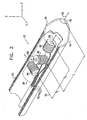
- Fig. 2 is a schematic, pictorial illustration of distal end 22 of catheter 20, in accordance with a preferred embodiment of the present invention.
- Distal end 22 comprises a functional portion 24 for performing diagnostic and/or therapeutic functions, adjacent to a distal tip 26 of the catheter.
- Functional portion 24 comprises an ultrasound transducer 50, typically used for ultrasound imaging within a patient. Alternatively, ultrasound transducer 50 is used for other diagnostic purposes, such as Doppler measurements, or for therapeutic uses.
- Distal end 22 of catheter 20 further includes a position sensing device 28 that generates signals used to determine the position and orientation of the catheter within the body.
- Position sensing device 28 is preferably adjacent to functional portion 24. There is preferably a fixed positional and orientational relationship between position sensing device 28 and portion 24.
- Position sensing device 28 preferably comprises three non-concentric coils 60, 62 and 64, such as described in the above-cited EP-A-0 776 176 .
- This device enables continuous generation of six dimensions of position and orientation information.
- Coils 60, 62 and 64 have respective axes 66, 68 and 70 which preferably but not necessarily define orthogonal Cartesian axes Z, X and Y, respectively, as shown in Fig. 2 , wherein the Z-axis is parallel to the long axis of catheter 20 and the X- and Y-axes define a plane perpendicular thereto.
- the coils each have a fixed position and orientation with respect to each other.
- preferred embodiments of the present invention are described herein with reference to the position signal generating device shown in Fig. 2 and described above, it is to be understood that the inventive concepts of the present invention are similarly applicable to probes including other position sensing devices.
- preferred embodiments of the present invention may comprise a single coil for generating position signals, or two or more such coils, which may be concentric or non-concentric.
- Other preferred embodiments of the present invention may comprise other types of position sensing devices, such as Hall effect devices.
- position sensing device 28 is located in catheter 20 at a distance L from distal tip 26, where L is here defined for convenience as the distance along the Z-axis from central axis 68 of coil 62 to tip 26.
- L is here defined for convenience as the distance along the Z-axis from central axis 68 of coil 62 to tip 26.
- Respective axes 66 and 70 of coils 60 and 64 are displaced from axis 68 by respective distances d y and d z .
- Signal processing circuits 40 in console 34 receive signals carried by coil wires 72 from coils 60, 62, and 64, and convey them to computer 36, which computes the three-dimensional translational position of position sensing device 28 and the rotational orientation of axes 66, 68 and 70, relative to a fixed, external coordinate frame.
- the actual position and orientation of distal tip 26 are then computed by taking into account the distance L of tip 26 from the center of position sensing device 28, as defined by axis 68, and the orientation of axes 66, 68 and 70.
- axis 66 of coil 60 typically deviates from absolute alignment with the long axis of catheter 20, which passes through tip 26.
- axes 68 and 70 of coils 62 and 64 respectively are typically not precisely orthogonal to axis 66 or to each other, thereby inducing additional errors in determination of position and orientation of the catheter.
- axis 52 of ultrasound transducer 50 typically deviates from absolute alignment with the long axis of catheter 20, and from axis 66 of coil 60.
- variations in the respective gains of coils 60, 62 and 64 and in the distances d y and d z may cause additional errors in determination of position and orientation of the catheter.
- position sensing device 28 and ultrasound transducer 50 are calibrated before the catheter is inserted into a patient's body.
- this calibration is performed using one or more jigs, such as those shown, for example, in Figs. 3A, 3B and 3C .
- Figs. 3A, 3B and 3C show a preferred embodiment of a jig 77 for use in calibrating the gains and deviations from orthogonality of coils 60, 62 and 64, and for calibrating the ultrasound transducer's deviation from alignment with the long axis of catheter 20, and from axis 66 of coil 60.
- Jig 77 comprises three mutually-orthogonal pairs of parallel radiator coils 79, 81 and 83, mounted on a base 85.
- the radiator coils are coupled to radiator driver circuitry (not shown), which causes the radiator coils to generate magnetic fields.
- Each radiator coil pair generates a magnetic field that is substantially normal to the planes defined by the pair of coils, and is thus substantially orthogonal to fields generated by the other two radiator coil pairs.
- the radiator coils are configured so as to generate predetermined, substantially uniform magnetic fields in a region adjacent to the center of the jig, i.e., in a region centrally located in between the three pairs of radiator coils.
- the driver circuitry is configured so that the amplitudes of the respective magnetic fields generated by the three radiator coil pairs are equal.
- jig 77 further comprises a catheter clamp assembly 87, which is located inside the jig and not seen in Fig. 3A .
- clamp assembly 87 comprises a clamp base 89.
- Clamp base 89 comprises a universal joint 103, which is able to pivot on the rotational axes of pitch and yaw with respect to the long axis of catheter 20.
- a base portion of universal joint 103 is typically fixed to a housing supporting one or more of radiator coils 79, 81 and 83 in a known position and orientation.
- clamp assembly 87 is constructed and configured in jig 77 so that a catheter held in the clamp assembly will be in the region of substantially uniform magnetic fields adjacent to the center of the jig, and so that the long axis of the catheter will be substantially normal to the planes defined by one of the pairs of parallel radiator coils (for example, coils 83 as shown in Fig. 3B ).
- a clamp cover 91 is rotatably attached to base 89 by a hinge 93.
- Base 89 and cover 91 include respective semi-circular grooves 95 and 97, whose radii are substantially equal to the radius of catheter 20, and which together comprise circular groove 94 (shown in Fig. 3B ).
- jig 77 further comprises an ultrasound target 27 of known geometry, size, and material, fixed in a known position.
- Target 27 for example, may comprise a small "bubble" made of ultrasound-reflecting material.
- Target 27 may also be of different geometries and/or sizes.
- Clamp assembly 89 preferably includes a heating element 99 and at least one temperature sensor 101, which are used to heat distal end 22 of catheter 20 to a temperature substantially equal to the temperature of the body into which the catheter is to be inserted, and to maintain the distal end at that temperature during calibration.
- the response of coils 60, 62 and 64 to magnetic fields may change as a function of temperature.
- distal end 22 is typically heated to and maintained at a temperature of 37 degrees C during calibration, although other temperatures may be chosen, for example when catheter 20 is to be used under conditions of hypothermia, such as are generally induced during open-heart surgery.
- the catheter is inserted in groove 95 with distal end 22 of the catheter pointing in the direction of target 27.
- Distal end 22 is preferably inserted into clamp assembly 87 so that it protrudes therefrom by a predetermined distance.
- the desired distance may be indicated, for example, by fiducial marks or other features (not shown) on the catheter's outer surface.
- the catheter is rotated about its long axis to a desired rotational orientation, wherein preferably the X, Y and Z catheter axes shown in Fig. 2 are substantially aligned with the magnetic field directions defined by radiator coil pairs 83, 79 and 81, respectively.
- the rotational orientation is unimportant.
- cover 91 is then lowered to hold the catheter in place. In this manner the catheter is fixed in a known orientation relative to the magnetic fields generated by radiator coils 81, 83 and 85, and relative to target 27.
- the respective gains and angular orientations of catheter coils 60, 62 and 64 are then calibrated by sequentially activating radiator coil pairs 79, 81 and 83 to generate predetermined, known magnetic fields, and measuring the amplitudes of the signals generated by the catheter coils.
- total amplitudes of the respective catheter coil signals are derived by summing the squares of the amplitudes of the signals generated by each of catheter coils 60, 62 and 64 in response to each of the coil pairs in turn. Since the magnetic fields in the vicinity of coils 60, 62 and 64 have equal and substantially uniform components along each of the coil axes 66, 68 and 70, the total signal amplitudes will be independent of the respective orientations and positions of coils 60, 62 and 64, and will depend only on the respective coil gains. Thus, the measured total signal amplitudes may be used to determine respective normalization factors for coils 60, 62 and 64, by dividing the measured amplitudes by expected standard values. Subsequently the amplitudes of signals received from these coils may be multiplied by the respective normalization factors in order to correct for gain variations.
- Jig 77 is further used to calibrate the respective angular orientations of coils 60, 62 and 64 relative to catheter 20, so as to correct for deviations from orthogonality.
- the normalized amplitude of the signal generated by each of coils 60, 62 and 64 in response to each of the magnetic fields will be proportional to the cosine of the angle between the respective coil axis 66, 68 or 70, and the direction of the applied magnetic field.
- Three such angle cosines, corresponding to the directions of the three orthogonal magnetic fields applied by radiator coil pairs 79, 81 and 83, may thus be derived for each of catheter coils 60, 62 and 64.
- catheter 20 is held in clamp assembly 87 in such a manner that the X, Y and Z catheter axes are substantially aligned with the three orthogonal magnetic field directions, the orientations of the coils relative to the catheter axes may thus be determined.
- a normalized amplitude of the signal received from coil 60, S 60 (Z) is received and measured.
- the X- and Y-axis fields are similarly activated, and corresponding normalized signals S 60 (X) and S 60 (Y) are received.
- S 60 (X), S 60 (Y) and S 60 (Z) are used to calculate coil angle calibration factors for coil 60, which are thereafter recorded in catheter 20 and used in determining the catheter's position and orientation.
- a similar procedure is used to calibrate coils 62 and 64.
- a master coil (not shown) is used to calibrate jig 77, preferably as described in the above-cited US-A-6,266,551 .
- the signals received from coils 60, 62 and 64 are preferably first corrected to account for the calibration factors of coil pairs 79, 81 and 83, and, subsequently, the gain normalization and angle calibration factors of the catheter described hereinabove are determined.
- jig 77 is further used to calibrate the angular orientation of ultrasound transducer 50 relative to position sensing device 28 and to catheter 20.
- Ultrasound transducer 50 emits ultrasonic radiation and generates an output signal responsive to the radiation reflected back from target 27.
- the roll, yaw, and/or pitch of the angular orientation of distal end 22 of catheter 20 are varied until the output signal indicates that ultrasound transducer 50 is in a suitable alignment with target 27.
- This alignment is preferably performed by forming an image of the target, or, alternatively, by using other methods that will be apparent to those skilled in the art, having read the disclosure of the present patent application. Methods of honing in on the target will also be apparent to those skilled in the art.
- the manipulation of the angular orientation of the catheter can be performed manually or by automated means.
- the angles of the yaw and pitch of distal end 22 relative to fixed and known axis 29 extending from the center of groove 94 ( Fig. 3B ) to target 27 are measured.
- This measurement is preferably performed with position sensing device 28 by comparing the device's current orientation, in alignment with the target, with its orientation prior to aligning the ultrasound transducer with the target.
- the measurement is performed using mechanical means known in the art.
- the distances between the distal end of ultrasound transducer 50 and the center of groove 94, between the distal end of ultrasound transducer 50 and target 27, and between the distal end of ultrasound transducer 50 and position sensing device 28 are known, so using the measured angles and these distances, the exact orientation of axis 52 of ultrasound transducer 50 relative to position sensing device 28, and the exact orientation of axis 52 relative to the long axis of catheter 20 are readily calculated. (Any change in the distance between tip 26 and target 27 caused by the pivoting of universal joint 103 can readily be calculated and compensated for.)
- this displacement is calibrated.
- methods described hereinabove are used to perform this calibration.
- the respective angular orientations of coils 60, 62 and 64 relative to ultrasound transducer 50 are directly calculated.
- the intermediary step of calibrating the orientations of the coils relative to catheter 20 is not performed. This calibration technique is particularly advantageous for applications in which catheter 20 does not comprise diagnostic or therapeutic elements other than the ultrasound transducer, because in such applications there is generally no need to know the precise orientation of the catheter during a procedure.
- ultrasound transducer 50 is disposed perpendicular to the long axis of catheter 20, rather than parallel to this long axis. Calibration techniques described herein are modified appropriately.
- catheter 20 is held in a fixed position in the jig during calibration, and ultrasound target 27 is moved in the jig until ultrasound transducer 50 is brought into alignment with the target.
- the displacements of coils 60, 62 and 64 relative to catheter tip 26 are calibrated. This is preferably performed by using a jig (not shown) and methods for this purpose, such as those described in the above-cited US-A-6,266,551 .
- the calibration corrections that are determined in accordance with the methods described hereinabove are thereafter stored electronically in a memory device, which is preferably incorporated in catheter 20.
- a memory device which is preferably incorporated in catheter 20.
- this memory device is accessible to computer 36 in the console. Apparatus and methods for enabling the use of such a memory device that are described in the above-cited US-A-6,266,551 may be used, or, alternatively, other apparatus and methods known in the art may be used.
- embodiments of the present invention have been described with respect to an ultrasound transducer, it is to be understood that apparatus and methods described herein are equally applicable to devices on a catheter that perform other imaging modalities. Additionally, although embodiments of the present invention have been described to include the steps of calibrating the gains of the coils, calibrating the respective angular orientations of the coils relative to the catheter, and calibrating the displacements of the coils relative to the catheter tip, these steps can optionally be omitted. Furthermore, although embodiments of the present invention have been described with respect to coil-based position sensors, the techniques described herein are similarly applicable to position sensors that are not coil-based.
Landscapes
- Health & Medical Sciences (AREA)
- Life Sciences & Earth Sciences (AREA)
- Engineering & Computer Science (AREA)
- Surgery (AREA)
- Animal Behavior & Ethology (AREA)
- General Health & Medical Sciences (AREA)
- Biomedical Technology (AREA)
- Heart & Thoracic Surgery (AREA)
- Medical Informatics (AREA)
- Molecular Biology (AREA)
- Veterinary Medicine (AREA)
- Public Health (AREA)
- Nuclear Medicine, Radiotherapy & Molecular Imaging (AREA)
- Physics & Mathematics (AREA)
- Biophysics (AREA)
- Pathology (AREA)
- Radiology & Medical Imaging (AREA)
- Robotics (AREA)
- Human Computer Interaction (AREA)
- Ultra Sonic Daignosis Equipment (AREA)
Claims (51)
- Procédé d'étalonnage comprenant les étapes qui consistent à :placer une sonde (20) qui présente une pointe distale (26), un détecteur de position (28) et un dispositif d'imagerie (50) dans un ensemble de test (77) dans lequel une cible d'imagerie (27) est disposée en une position connue,manipuler la sonde dans l'ensemble de test tout en faisant fonctionner le dispositif d'imagerie jusqu'à ce qu'un signal délivré par le dispositif d'imagerie indique que le dispositif d'imagerie est aligné sur la cible d'imagerie,mesurer un signal de position formé par le détecteur de position pendant que le dispositif d'imagerie est aligné sur la cible d'imagerie de manière à déterminer l'orientation de la sonde dans un cadre de référence de l'ensemble de test etdéterminer des données d'étalonnage de la sonde en réponse à l'orientation de la sonde,la détermination des données d'étalonnage comprenant l'étalonnage du déplacement du dispositif d'imagerie (50) par rapport à la pointe distale (26).
- Procédé selon la revendication 1, dans lequel le dispositif d'imagerie est un transducteur d'ultrasons et la cible d'imagerie une cible à ultrasons.
- Procédé selon la revendication 2, dans lequel les données d'étalonnage comprennent l'alignement du transducteur d'ultrasons par rapport à l'axe de la sonde et dans lequel la détermination des données d'étalonnage comprend la détermination de l'alignement.
- Procédé selon la revendication 2 ou la revendication 3, dans lequel les données d'étalonnage comprennent l'alignement du transducteur d'ultrasons par rapport au détecteur de position et dans lequel la détermination des données d'étalonnage comprend la détermination de l'alignement.
- Procédé selon l'une quelconque des revendications 2 à 4, dans lequel les données d'étalonnage comprennent l'alignement du transducteur d'ultrasons par rapport au détecteur de position et l'alignement du transducteur d'ultrasons par rapport à l'axe de la sonde et dans lequel la détermination des données d'étalonnage comprend la détermination des alignements.
- Procédé selon l'une quelconque des revendications 2 à 5, dans lequel la détermination des données d'étalonnage comprend la détermination des données d'étalonnage de la sonde en réponse à l'orientation de la sonde et à la position connue de la cible à ultrasons par rapport à l'ensemble de test.
- Procédé selon l'une quelconque des revendications 1 à 6, dans lequel la manipulation de la sonde comprend la modification de l'axe de rotation de la sonde, sélectionnée dans l'ensemble constitué d'un roulis de la sonde, d'un lacet de la sonde et d'un tangage de la sonde.
- Procédé selon l'une quelconque des revendications 2 à 7, dans lequel la manipulation de la sonde comprend la manipulation de la sonde dans l'ensemble de test tout en faisant fonctionner le transducteur d'ultrasons de manière à former une image de la sonde à ultrasons jusqu'à ce que le signal délivré indique que le transducteur est aligné sur la cible à ultrasons.
- Procédé selon l'une quelconque des revendications 1 à 8, dans lequel la manipulation de la sonde comprend la manipulation manuelle de la sonde.
- Procédé selon l'une quelconque des revendications 1 à 8, dans lequel la manipulation de la sonde comprend la manipulation automatique de la sonde.
- Procédé selon l'une quelconque des revendications 1 à 10, dans lequel la mesure du signal de position comprend la formation d'au moins deux champs magnétiques dans l'ensemble de test.
- Procédé selon l'une quelconque des revendications 1 à 11, dans lequel le détecteur de position comprend au moins deux bobinages (60, 62, 64) et dans lequel la mesure du signal de position comprend la mesure d'un signal pour chacun des bobinages.
- Procédé selon l'une quelconque des revendications 1 à 12, dans lequel la manipulation de la sonde comprend la rotation de la sonde autour de l'axe longitudinal de la sonde.
- Procédé selon l'une quelconque des revendications 1 à 13, dans lequel la mesure du signal de position comprend une modification de la température de la sonde.
- Procédé selon la revendication 14, dans lequel la modification de la température de la sonde comprend le chauffage de la sonde.
- Procédé selon la revendication 14, dans lequel la modification de la température de la sonde comprend le refroidissement de la sonde.
- Procédé selon l'une quelconque des revendications 1 à 16, dans lequel la sonde comprend un microcircuit programmable et dans lequel la détermination des données d'étalonnage comprend l'enregistrement des données d'étalonnage dans le microcircuit.
- Procédé selon la revendication 17, dans lequel l'enregistrement des données d'étalonnage comprend le cryptage d'un code d'étalonnage.
- Procédé selon l'une quelconque des revendications 1 à 18, dans lequel l'ensemble de test comprend un ensemble de pince et dans lequel le placement de la sonde dans l'ensemble de test comprend le placement de la sonde dans l'ensemble de pince.
- Procédé selon la revendication 19, dans lequel l'ensemble de pince est configuré de manière à définir une rainure (95) et dans lequel le placement de la sonde dans l'ensemble de test comprend le placement de la sonde dans la rainure.
- Procédé selon l'une quelconque des revendications 1 à 20, dans lequel l'ensemble de test comprend au moins deux bobinages de radiateur (73, 79, 81) fixés dans des positions connues et dans lequel le placement de la sonde comprend l'alignement de la sonde dans une orientation connue par rapport au bobinage de radiateur,
dans lequel la mesure du signal de position comprend l'activation des bobinages de radiateur de manière à produire des champs magnétiques connus dans l'ensemble de test et à mesurer un signal de position d'étalonnage de détecteur de position produit par le détecteur de position de manière à déterminer l'orientation du détecteur de position par rapport à l'axe de la sonde et
dans lequel la détermination des données d'étalonnage comprend la détermination des données d'étalonnage de détecteur de position de la sonde en réponse à l'orientation du détecteur de position. - Procédé selon la revendication 21, dans lequel la détermination des données d'étalonnage du détecteur de position comprend la détermination de la mesure du déplacement (L) du détecteur de position par rapport à la pointe distale.
- Procédé selon la revendication 21 dans la mesure où elle dépend de la revendication 2, dans lequel la mesure du signal de position comprend la mesure du signal de position de manière à déterminer l'orientation du transducteur d'ultrasons par rapport au détecteur de position et dans lequel la détermination des données d'étalonnage de la sonde comprend la détermination de l'alignement du transducteur d'ultrasons par rapport à l'axe de la sonde en réponse à l'orientation du transducteur d'ultrasons par rapport au détecteur de position et en réponse à l'orientation du détecteur de position par rapport à l'axe de la sonde.
- Procédé selon la revendication 21, dans lequel le détecteur de position comprend au moins deux bobinages (60, 62, 64) et dans lequel la mesure du signal de position d'étalonnage du détecteur de position comprend la mesure d'un signal d'étalonnage de chacun des bobinages.
- Procédé selon la revendication 24, dans lequel la détermination des données d'étalonnage du détecteur de position de la sonde comprend l'étalonnage d'un gain de chaque bobinage.
- Procédé selon la revendication 24, dans lequel la détermination des données d'étalonnage du détecteur de position de la sonde comprend la détermination pour chaque bobinage d'une déviation du bobinage par rapport à un alignement sur l'axe de la sonde.
- Appareil d'étalonnage d'une sonde (20) présentant une pointe distale (26), un détecteur de position (28) et un dispositif d'imagerie (50), l'appareil comprenant :un ensemble de test (77),l'appareil étant caractérisé en ce que l'ensemble de test comprend une cible d'imagerie (27) qui y est disposée en une position connue, l'appareil comprenant en outreun ordinateur adapté pour :recevoir un signal de position produit par le détecteur de position pendant que le dispositif d'imagerie est aligné sur la cible d'imagerie,déterminer l'orientation de la sonde dans un cadre de référence de l'ensemble de test etdéterminer des données d'étalonnage de la sonde en réponse à l'orientation de la sonde,l'ordinateur étant adapté pour étalonner le déplacement du dispositif d'imagerie (50) par rapport à la pointe distale (26).
- Appareil selon la revendication 27, dans lequel le dispositif d'imagerie est un transducteur d'ultrasons et la cible d'imagerie est une cible d'ultrasons.
- Appareil selon la revendication 28, dans lequel les données d'étalonnage comprennent l'alignement du transducteur d'ultrasons par rapport à l'axe de la sonde et dans lequel l'ordinateur est adapté pour déterminer l'alignement.
- Appareil selon la revendication 28 ou la revendication 29, dans lequel les données d'étalonnage comprennent l'alignement du transducteur d'ultrasons par rapport au détecteur de position et dans lequel l'ordinateur est adapté pour déterminer l'alignement.
- Procédé selon l'une quelconque des revendications 28 à 30, dans lequel les données d'étalonnage comprennent l'alignement du transducteur d'ultrasons par rapport au détecteur de position et l'alignement du transducteur d'ultrasons par rapport à l'axe de la sonde et dans lequel l'ordinateur est adapté pour déterminer les alignements.
- Procédé selon l'une quelconque des revendications 28 à 31, dans lequel l'ordinateur est adapté pour déterminer les données d'étalonnage de la sonde en réponse à l'orientation de la sonde et à la position connue de la cible à ultrasons par rapport à l'ensemble de test.
- Procédé selon l'une quelconque des revendications 28 à 32, dans lequel la sonde d'ultrasons comprend une bulle qui contient un matériau réfléchissant les ultrasons.
- Procédé selon l'une quelconque des revendications 28 à 33, dans lequel le détecteur de position comprend au moins deux bobinages (60, 62, 64) et dans lequel l'ordinateur est adapté pour recevoir le signal de position en réponse au courant qui s'écoule dans les bobinages.
- Procédé selon l'une quelconque des revendications 28 à 34, dans lequel l'ensemble de test comprend un élément chauffant (99) adapté pour chauffer la sonde.
- Procédé selon l'une quelconque des revendications 28 à 35, dans lequel l'ensemble d'ultrasons est adapté pour pouvoir être déplacé à l'intérieur de l'ensemble de test.
- Procédé selon l'une quelconque des revendications 28 à 36, dans lequel la sonde contient un microcircuit programmable et dans lequel l'ordinateur est adapté pour enregistrer les données d'étalonnage dans le microcircuit.
- Appareil selon la revendication 37, dans lequel l'ordinateur est adapté pour crypter un code d'étalonnage.
- Procédé selon l'une quelconque des revendications 28 à 38, dans lequel l'ensemble de test comprend un ensemble de pince (87) adapté à maintenir la sonde.
- Appareil selon la revendication 39, dans lequel l'ensemble de pince est adapté pour permettre de modifier l'orientation de la sonde sur un axe de rotation de la sonde sélectionné dans l'ensemble constitué d'un roulis de la sonde, d'un lacet de la sonde et d'un tangage de la sonde.
- Appareil selon la revendication 40, dans lequel l'ensemble de pince est configuré pour définir une rainure (95) adaptée pour maintenir la sonde.
- Appareil selon la revendication 39, dans lequel l'ensemble de pince est adapté pour manipuler la sonde de manière automatique.
- Procédé selon l'une quelconque des revendications 28 à 42, dans lequel l'ensemble de test comprend au moins deux bobinages du radiateur (79, 81, 83) fixés en des positions connues.
- Appareil selon la revendication 43, dans lequel l'ensemble de test comprend trois paires mutuellement orthogonales de bobinages de radiateur (79, 81, 83) parallèles.
- Appareil selon la revendication 44, dans lequel les bobinages de radiateur sont adaptés pour produire des champs magnétiques respectifs dans l'ensemble de test et dans lequel l'ordinateur est adapté pour recevoir le signal de position produit par le détecteur de position en réponse au champ magnétique.
- Appareil selon la revendication 44, dans lequel l'ordinateur est adapté pour
recevoir le signal de position d'étalonnage de détecteur de position produit par le détecteur de position pendant que la sonde est alignée dans une orientation connue par rapport aux bobinages de radiateur,
déterminer l'orientation du détecteur de position par rapport à un axe de la sonde et
déterminer des données d'étalonnage du détecteur de position de la sonde en réponse à l'orientation du détecteur de position. - Appareil selon la revendication 46, dans lequel les données d'étalonnage du détecteur de position comprennent une mesure du déplacement (L) du détecteur de position par rapport à la pointe distale et dans lequel l'ordinateur est adapté pour déterminer la mesure du déplacement.
- Appareil selon la revendication 46, dans lequel les données d'étalonnage de la sonde comprennent l'alignement du transducteur d'ultrasons par rapport à l'axe de la sonde et dans lequel l'ordinateur est adapté pour
déterminer l'orientation du transducteur d'ultrasons par rapport au détecteur de position et
déterminer l'alignement du transducteur d'ultrasons par rapport à l'axe de la sonde en réponse à l'orientation du transducteur d'ultrasons par rapport au détecteur de position et en réponse à l'orientation du détecteur de position par rapport à l'axe de la sonde. - Appareil selon la revendication 46, dans lequel le détecteur de position comprend au moins deux bobinages et dans lequel l'ordinateur est adapté pour mesurer un signal d'étalonnage pour chacun des bobinages.
- Appareil selon la revendication 49, dans lequel l'ordinateur est adapté pour étalonner le gain de chaque bobinage.
- Appareil selon la revendication 49, dans lequel l'ordinateur est adapté pour déterminer pour chaque bobinage la déviation du bobinage par rapport à son alignement sur l'axe de la sonde.
Applications Claiming Priority (2)
| Application Number | Priority Date | Filing Date | Title |
|---|---|---|---|
| US10/447,940 US7090639B2 (en) | 2003-05-29 | 2003-05-29 | Ultrasound catheter calibration system |
| US447940 | 2003-05-29 |
Publications (2)
| Publication Number | Publication Date |
|---|---|
| EP1481637A1 EP1481637A1 (fr) | 2004-12-01 |
| EP1481637B1 true EP1481637B1 (fr) | 2013-03-06 |
Family
ID=33131603
Family Applications (1)
| Application Number | Title | Priority Date | Filing Date |
|---|---|---|---|
| EP04253230A Expired - Lifetime EP1481637B1 (fr) | 2003-05-29 | 2004-05-28 | Système d'étalonnage pour un cathéter d'ultrason |
Country Status (7)
| Country | Link |
|---|---|
| US (1) | US7090639B2 (fr) |
| EP (1) | EP1481637B1 (fr) |
| JP (1) | JP2004351214A (fr) |
| KR (1) | KR20040103413A (fr) |
| AU (1) | AU2004202165C1 (fr) |
| CA (1) | CA2468226C (fr) |
| IL (1) | IL162036A (fr) |
Cited By (2)
| Publication number | Priority date | Publication date | Assignee | Title |
|---|---|---|---|---|
| CN106510762A (zh) * | 2017-01-04 | 2017-03-22 | 青岛大学附属医院 | 一种耳鼻喉科的超声波探头 |
| CN108136205A (zh) * | 2015-10-21 | 2018-06-08 | 皇家飞利浦有限公司 | 支持对对象的处置的系统 |
Families Citing this family (169)
| Publication number | Priority date | Publication date | Assignee | Title |
|---|---|---|---|---|
| ATE523141T1 (de) | 2004-02-17 | 2011-09-15 | Philips Electronics Ltd | Verfahren und vorrichtung zur registrierung, verifizierung von und bezugnahme auf körperorgane(n) |
| EP1744676B1 (fr) * | 2004-04-15 | 2015-07-22 | The Johns Hopkins University | Etalonnage ultrasonore et assurance qualite en temps reel reposant sur une expression en forme analytique |
| CA2586560A1 (fr) | 2004-11-05 | 2006-06-01 | The Government Of The United States Of America, As Represented By The Se Cretary, Department Of Health And Human Services | Systeme d'acces |
| US7805269B2 (en) | 2004-11-12 | 2010-09-28 | Philips Electronics Ltd | Device and method for ensuring the accuracy of a tracking device in a volume |
| US7751868B2 (en) | 2004-11-12 | 2010-07-06 | Philips Electronics Ltd | Integrated skin-mounted multifunction device for use in image-guided surgery |
| US7713210B2 (en) | 2004-11-23 | 2010-05-11 | St. Jude Medical, Atrial Fibrillation Division, Inc. | Method and apparatus for localizing an ultrasound catheter |
| WO2006078677A2 (fr) | 2005-01-18 | 2006-07-27 | Traxtal Technologies Inc. | Dispositif a fil k guide electromagnetiquement |
| EP1838378B1 (fr) | 2005-01-18 | 2017-03-22 | Philips Electronics LTD | Appareil de guidage d'un instrument jusqu'a une region cible d'un poumon |
| WO2007002079A2 (fr) | 2005-06-21 | 2007-01-04 | Traxtal Inc. | Système, procédé et appareil pour thérapie et diagnostic avec navigation |
| US9398892B2 (en) | 2005-06-21 | 2016-07-26 | Koninklijke Philips N.V. | Device and method for a trackable ultrasound |
| KR100668092B1 (ko) * | 2005-06-30 | 2007-01-15 | 한국표준과학연구원 | 영상장치의 어레이 프로브 시스템 및 그 제어방법 |
| EP1924197B1 (fr) | 2005-08-24 | 2017-10-11 | Philips Electronics LTD | Systeme d'endoscopie souple de navigation |
| US8784336B2 (en) | 2005-08-24 | 2014-07-22 | C. R. Bard, Inc. | Stylet apparatuses and methods of manufacture |
| US7874987B2 (en) * | 2005-10-28 | 2011-01-25 | Biosense Webster, Inc. | Targets and methods for ultrasound catheter calibration |
| WO2007051261A1 (fr) * | 2005-11-07 | 2007-05-10 | Signostics Pty Ltd | Systeme et procede de mesure ultrasonore |
| US7677078B2 (en) * | 2006-02-02 | 2010-03-16 | Siemens Medical Solutions Usa, Inc. | Line-based calibration of ultrasound transducer integrated with a pose sensor |
| US8105239B2 (en) | 2006-02-06 | 2012-01-31 | Maui Imaging, Inc. | Method and apparatus to visualize the coronary arteries using ultrasound |
| US7860553B2 (en) * | 2006-02-09 | 2010-12-28 | Biosense Webster, Inc. | Two-stage calibration of medical probes |
| US8798711B2 (en) * | 2006-02-09 | 2014-08-05 | Biosense Webster, Inc. | Shielding of catheter handle |
| WO2007097247A1 (fr) * | 2006-02-24 | 2007-08-30 | Hrs Consultant Service, Inc. | Dispositif educatif de diagnostic echocardiographique transoesophagien |
| US8388546B2 (en) | 2006-10-23 | 2013-03-05 | Bard Access Systems, Inc. | Method of locating the tip of a central venous catheter |
| US7794407B2 (en) | 2006-10-23 | 2010-09-14 | Bard Access Systems, Inc. | Method of locating the tip of a central venous catheter |
| WO2008051639A2 (fr) | 2006-10-25 | 2008-05-02 | Maui Imaging, Inc. | Procédé et appareil de production d'images ultrasonores au moyen d'une pluralité d'orifices |
| AU2008200422B2 (en) * | 2007-01-31 | 2012-11-08 | Biosense Webster, Inc. | Ultrasound catheter calibration with enhanced accuracy |
| US7996057B2 (en) | 2007-01-31 | 2011-08-09 | Biosense Webster, Inc. | Ultrasound catheter calibration with enhanced accuracy |
| US7735349B2 (en) * | 2007-01-31 | 2010-06-15 | Biosense Websters, Inc. | Correlation of ultrasound images and gated position measurements |
| US8057397B2 (en) * | 2007-05-16 | 2011-11-15 | General Electric Company | Navigation and imaging system sychronized with respiratory and/or cardiac activity |
| US7940972B2 (en) * | 2007-05-16 | 2011-05-10 | General Electric Company | System and method of extended field of view image acquisition of an imaged subject |
| US9055883B2 (en) * | 2007-05-16 | 2015-06-16 | General Electric Company | Surgical navigation system with a trackable ultrasound catheter |
| US20080287805A1 (en) * | 2007-05-16 | 2008-11-20 | General Electric Company | System and method to guide an instrument through an imaged subject |
| US8527032B2 (en) * | 2007-05-16 | 2013-09-03 | General Electric Company | Imaging system and method of delivery of an instrument to an imaged subject |
| US7909767B2 (en) * | 2007-05-16 | 2011-03-22 | General Electric Company | Method for minimizing tracking system interference |
| US8213693B1 (en) | 2007-05-16 | 2012-07-03 | General Electric Company | System and method to track and navigate a tool through an imaged subject |
| US8790262B2 (en) * | 2007-05-16 | 2014-07-29 | General Electric Company | Method for implementing an imaging and navigation system |
| US8989842B2 (en) | 2007-05-16 | 2015-03-24 | General Electric Company | System and method to register a tracking system with intracardiac echocardiography (ICE) imaging system |
| US8428690B2 (en) | 2007-05-16 | 2013-04-23 | General Electric Company | Intracardiac echocardiography image reconstruction in combination with position tracking system |
| US8364242B2 (en) | 2007-05-17 | 2013-01-29 | General Electric Company | System and method of combining ultrasound image acquisition with fluoroscopic image acquisition |
| US10226234B2 (en) | 2011-12-01 | 2019-03-12 | Maui Imaging, Inc. | Motion detection using ping-based and multiple aperture doppler ultrasound |
| US9282945B2 (en) * | 2009-04-14 | 2016-03-15 | Maui Imaging, Inc. | Calibration of ultrasound probes |
| US8535308B2 (en) | 2007-10-08 | 2013-09-17 | Biosense Webster (Israel), Ltd. | High-sensitivity pressure-sensing probe |
| US8357152B2 (en) | 2007-10-08 | 2013-01-22 | Biosense Webster (Israel), Ltd. | Catheter with pressure sensing |
| WO2009063360A1 (fr) * | 2007-11-14 | 2009-05-22 | Koninklijke Philips Electronics, N.V. | Système et procédé pour le calibrage automatique d'ultrason localisé |
| CN101925333B (zh) | 2007-11-26 | 2014-02-12 | C·R·巴德股份有限公司 | 用于脉管系统内的导管放置的集成系统 |
| US10524691B2 (en) | 2007-11-26 | 2020-01-07 | C. R. Bard, Inc. | Needle assembly including an aligned magnetic element |
| US9521961B2 (en) | 2007-11-26 | 2016-12-20 | C. R. Bard, Inc. | Systems and methods for guiding a medical instrument |
| US10751509B2 (en) | 2007-11-26 | 2020-08-25 | C. R. Bard, Inc. | Iconic representations for guidance of an indwelling medical device |
| US12440238B2 (en) | 2007-11-26 | 2025-10-14 | C. R. Bard, Inc. | Apparatus for use with needle insertion guidance system |
| US10449330B2 (en) | 2007-11-26 | 2019-10-22 | C. R. Bard, Inc. | Magnetic element-equipped needle assemblies |
| US8781555B2 (en) | 2007-11-26 | 2014-07-15 | C. R. Bard, Inc. | System for placement of a catheter including a signal-generating stylet |
| US8849382B2 (en) | 2007-11-26 | 2014-09-30 | C. R. Bard, Inc. | Apparatus and display methods relating to intravascular placement of a catheter |
| US9649048B2 (en) | 2007-11-26 | 2017-05-16 | C. R. Bard, Inc. | Systems and methods for breaching a sterile field for intravascular placement of a catheter |
| CA2650703C (fr) * | 2008-01-23 | 2016-10-04 | Mediguide Ltd. | Fil-guide flexible monte sur un capteur |
| US9095685B2 (en) | 2008-01-23 | 2015-08-04 | Mediguide Ltd. | Sensor mounted flexible guidewire |
| US8478382B2 (en) | 2008-02-11 | 2013-07-02 | C. R. Bard, Inc. | Systems and methods for positioning a catheter |
| US8437832B2 (en) | 2008-06-06 | 2013-05-07 | Biosense Webster, Inc. | Catheter with bendable tip |
| US9901714B2 (en) | 2008-08-22 | 2018-02-27 | C. R. Bard, Inc. | Catheter assembly including ECG sensor and magnetic assemblies |
| US9101734B2 (en) | 2008-09-09 | 2015-08-11 | Biosense Webster, Inc. | Force-sensing catheter with bonded center strut |
| US8437833B2 (en) | 2008-10-07 | 2013-05-07 | Bard Access Systems, Inc. | Percutaneous magnetic gastrostomy |
| US9326700B2 (en) | 2008-12-23 | 2016-05-03 | Biosense Webster (Israel) Ltd. | Catheter display showing tip angle and pressure |
| US8600472B2 (en) | 2008-12-30 | 2013-12-03 | Biosense Webster (Israel), Ltd. | Dual-purpose lasso catheter with irrigation using circumferentially arranged ring bump electrodes |
| US8475450B2 (en) | 2008-12-30 | 2013-07-02 | Biosense Webster, Inc. | Dual-purpose lasso catheter with irrigation |
| KR101659723B1 (ko) | 2009-04-14 | 2016-09-26 | 마우이 이미징, 인코포레이티드 | 복수 개구 초음파 어레이 정렬 설비 |
| DE102009021025A1 (de) * | 2009-05-13 | 2010-11-25 | Siemens Aktiengesellschaft | Medizinisches Navigationssystem |
| US9532724B2 (en) | 2009-06-12 | 2017-01-03 | Bard Access Systems, Inc. | Apparatus and method for catheter navigation using endovascular energy mapping |
| RU2549998C2 (ru) | 2009-06-12 | 2015-05-10 | Бард Аксесс Системс, Инк. | Способ позиционирования конца катетера |
| WO2011019760A2 (fr) | 2009-08-10 | 2011-02-17 | Romedex International Srl | Dispositifs et procédés pour électrographie endovasculaire |
| CN102665541B (zh) | 2009-09-29 | 2016-01-13 | C·R·巴德股份有限公司 | 与用于导管的血管内放置的设备一起使用的探针 |
| WO2011044421A1 (fr) | 2009-10-08 | 2011-04-14 | C. R. Bard, Inc. | Entretoises utilisées avec une sonde ultrasonore |
| US10688278B2 (en) | 2009-11-30 | 2020-06-23 | Biosense Webster (Israel), Ltd. | Catheter with pressure measuring tip |
| US8920415B2 (en) | 2009-12-16 | 2014-12-30 | Biosense Webster (Israel) Ltd. | Catheter with helical electrode |
| US8374819B2 (en) * | 2009-12-23 | 2013-02-12 | Biosense Webster (Israel), Ltd. | Actuator-based calibration system for a pressure-sensitive catheter |
| US8521462B2 (en) | 2009-12-23 | 2013-08-27 | Biosense Webster (Israel), Ltd. | Calibration system for a pressure-sensitive catheter |
| US8529476B2 (en) | 2009-12-28 | 2013-09-10 | Biosense Webster (Israel), Ltd. | Catheter with strain gauge sensor |
| US8608735B2 (en) | 2009-12-30 | 2013-12-17 | Biosense Webster (Israel) Ltd. | Catheter with arcuate end section |
| US8374670B2 (en) | 2010-01-22 | 2013-02-12 | Biosense Webster, Inc. | Catheter having a force sensing distal tip |
| WO2011097312A1 (fr) | 2010-02-02 | 2011-08-11 | C.R. Bard, Inc. | Appareil et procédé destinés à la navigation d'un cathéter et à la localisation d'une pointe |
| KR102322776B1 (ko) | 2010-02-18 | 2021-11-04 | 마우이 이미징, 인코포레이티드 | 초음파 이미지를 구성하는 방법 및 이를 위한 다중-개구 초음파 이미징 시스템 |
| US9706948B2 (en) * | 2010-05-06 | 2017-07-18 | Sachin Bhandari | Inertial sensor based surgical navigation system for knee replacement surgery |
| CA3054544C (fr) | 2010-05-28 | 2022-01-04 | C.R. Bard, Inc. | Appareil convenant a une utilisation avec un systeme de guidage d'insertion d'aiguille |
| EP2912999B1 (fr) | 2010-05-28 | 2022-06-29 | C. R. Bard, Inc. | Appareil destiné à être utilisé avec un système de guidage d'insertion d'aiguille |
| US8798952B2 (en) | 2010-06-10 | 2014-08-05 | Biosense Webster (Israel) Ltd. | Weight-based calibration system for a pressure sensitive catheter |
| US8226580B2 (en) | 2010-06-30 | 2012-07-24 | Biosense Webster (Israel), Ltd. | Pressure sensing for a multi-arm catheter |
| JP2013535301A (ja) | 2010-08-09 | 2013-09-12 | シー・アール・バード・インコーポレーテッド | 超音波プローブヘッド用支持・カバー構造 |
| US8380276B2 (en) | 2010-08-16 | 2013-02-19 | Biosense Webster, Inc. | Catheter with thin film pressure sensing distal tip |
| BR112013002431B1 (pt) | 2010-08-20 | 2021-06-29 | C.R. Bard, Inc | Sistema para a reconfirmação da posição de um cateter no interior de um paciente |
| US8731859B2 (en) | 2010-10-07 | 2014-05-20 | Biosense Webster (Israel) Ltd. | Calibration system for a force-sensing catheter |
| WO2012051305A2 (fr) | 2010-10-13 | 2012-04-19 | Mau Imaging, Inc. | Appareil interne de sonde à ouvertures multiples et systèmes de câbles |
| WO2012051308A2 (fr) | 2010-10-13 | 2012-04-19 | Maui Imaging, Inc. | Transducteurs à ultrasons concaves et réseaux 3d |
| CN103189009B (zh) | 2010-10-29 | 2016-09-07 | C·R·巴德股份有限公司 | 医疗设备的生物阻抗辅助放置 |
| US8979772B2 (en) | 2010-11-03 | 2015-03-17 | Biosense Webster (Israel), Ltd. | Zero-drift detection and correction in contact force measurements |
| US8333103B2 (en) * | 2011-03-30 | 2012-12-18 | Biosense Webster (Israel), Ltd. | Calibration of a force measuring system for large bend angles of a catheter |
| US9220433B2 (en) | 2011-06-30 | 2015-12-29 | Biosense Webster (Israel), Ltd. | Catheter with variable arcuate distal section |
| AU2012278809B2 (en) | 2011-07-06 | 2016-09-29 | C.R. Bard, Inc. | Needle length determination and calibration for insertion guidance system |
| US9662169B2 (en) | 2011-07-30 | 2017-05-30 | Biosense Webster (Israel) Ltd. | Catheter with flow balancing valve |
| USD724745S1 (en) | 2011-08-09 | 2015-03-17 | C. R. Bard, Inc. | Cap for an ultrasound probe |
| USD699359S1 (en) | 2011-08-09 | 2014-02-11 | C. R. Bard, Inc. | Ultrasound probe head |
| US8887551B2 (en) * | 2011-09-06 | 2014-11-18 | Trig Medical Ltd. | Calibration of instrument relative to ultrasonic probe |
| LT2939601T (lt) | 2011-09-06 | 2019-02-25 | Ezono Ag | Magnetinis medicininis įrenginys |
| FR2979742B1 (fr) | 2011-09-07 | 2014-06-27 | Commissariat Energie Atomique | Generateur d'un champ magnetique homogene |
| WO2013070775A1 (fr) | 2011-11-07 | 2013-05-16 | C.R. Bard, Inc | Insert à base d'hydrogel renforcé pour ultrasons |
| KR20140107648A (ko) | 2011-12-29 | 2014-09-04 | 마우이 이미징, 인코포레이티드 | 임의의 경로들의 m-모드 초음파 이미징 |
| US9687289B2 (en) | 2012-01-04 | 2017-06-27 | Biosense Webster (Israel) Ltd. | Contact assessment based on phase measurement |
| KR102134763B1 (ko) | 2012-02-21 | 2020-07-16 | 마우이 이미징, 인코포레이티드 | 다중의 어퍼처 초음파를 사용한 물질 강성의 결정 |
| EP2833791B1 (fr) | 2012-03-26 | 2022-12-21 | Maui Imaging, Inc. | Procédés pour l'amélioration de la qualité d'images ultrasonores par l'application de facteurs de pondération |
| WO2013145711A1 (fr) * | 2012-03-26 | 2013-10-03 | テルモ株式会社 | Dispositif de diagnostic d'image et procédé de commande pour celui-ci |
| EP2861153A4 (fr) | 2012-06-15 | 2016-10-19 | Bard Inc C R | Appareil et procédés permettant la détection d'un capuchon amovible sur une sonde à ultrasons |
| EP2883079B1 (fr) | 2012-08-10 | 2017-09-27 | Maui Imaging, Inc. | Étalonnage de sondes à ultrasons à ouvertures multiples |
| CN103676827A (zh) | 2012-09-06 | 2014-03-26 | Ip音乐集团有限公司 | 用于远程控制音频设备的系统和方法 |
| EP3893022B1 (fr) | 2012-09-06 | 2025-02-12 | Maui Imaging, Inc. | Architecture de mémoire de système d'imagerie par ultrasons |
| US20140188440A1 (en) | 2012-12-31 | 2014-07-03 | Intuitive Surgical Operations, Inc. | Systems And Methods For Interventional Procedure Planning |
| GB201303917D0 (en) | 2013-03-05 | 2013-04-17 | Ezono Ag | System for image guided procedure |
| US9257220B2 (en) | 2013-03-05 | 2016-02-09 | Ezono Ag | Magnetization device and method |
| US9459087B2 (en) | 2013-03-05 | 2016-10-04 | Ezono Ag | Magnetic position detection system |
| WO2014160291A1 (fr) | 2013-03-13 | 2014-10-02 | Maui Imaging, Inc. | Alignement de groupements de transducteurs à ultrasons et ensemble de sonde à ouvertures multiples |
| US9480415B2 (en) | 2013-04-26 | 2016-11-01 | Medtronic Navigation, Inc. | Electromagnetic coil apparatuses for surgical navigation and corresponding methods |
| US9883848B2 (en) | 2013-09-13 | 2018-02-06 | Maui Imaging, Inc. | Ultrasound imaging using apparent point-source transmit transducer |
| CN105979868B (zh) | 2014-02-06 | 2020-03-10 | C·R·巴德股份有限公司 | 用于血管内装置的导向和放置的系统和方法 |
| EP3182900B1 (fr) | 2014-08-18 | 2019-09-25 | Maui Imaging, Inc. | Système d'imagerie par ultrasons basée sur un réseau |
| US10869650B2 (en) * | 2014-11-06 | 2020-12-22 | Covidien Lp | System for tracking and imaging a treatment probe |
| EP3220828B1 (fr) | 2014-11-18 | 2021-12-22 | C.R. Bard, Inc. | Système d'imagerie à ultrasons ayant une présentation d'image automatique |
| WO2016081321A2 (fr) | 2014-11-18 | 2016-05-26 | C.R. Bard, Inc. | Système d'imagerie à ultrasons avec présentation d'image automatique |
| US10973584B2 (en) | 2015-01-19 | 2021-04-13 | Bard Access Systems, Inc. | Device and method for vascular access |
| WO2016160981A1 (fr) | 2015-03-30 | 2016-10-06 | Maui Imaging, Inc. | Systèmes d'imagerie par ultrasons et procédés de détection du mouvement d'un objet |
| US11096605B2 (en) | 2015-03-31 | 2021-08-24 | Medtronic Navigation, Inc. | Modular coil assembly |
| WO2016210325A1 (fr) | 2015-06-26 | 2016-12-29 | C.R. Bard, Inc. | Interface de raccord pour système de positionnement de cathéter basé sur ecg |
| US10856846B2 (en) | 2016-01-27 | 2020-12-08 | Maui Imaging, Inc. | Ultrasound imaging with sparse array probes |
| US11000207B2 (en) | 2016-01-29 | 2021-05-11 | C. R. Bard, Inc. | Multiple coil system for tracking a medical device |
| US20170307755A1 (en) | 2016-04-20 | 2017-10-26 | YoR Labs | Method and System for Determining Signal Direction |
| US20180098816A1 (en) * | 2016-10-06 | 2018-04-12 | Biosense Webster (Israel) Ltd. | Pre-Operative Registration of Anatomical Images with a Position-Tracking System Using Ultrasound |
| CN106943160A (zh) * | 2017-04-21 | 2017-07-14 | 天津工业大学 | 基于声波定位和生理参数检测的电子药丸 |
| CN110573074B (zh) | 2017-04-27 | 2022-07-12 | 巴德阿克塞斯系统股份有限公司 | 用于针组件的磁化系统 |
| CN107019513B (zh) * | 2017-05-18 | 2020-11-06 | 山东大学齐鲁医院 | 基于电磁定位复合导管的血管内虚拟内窥镜成像系统及其工作方法 |
| US10874327B2 (en) | 2017-05-19 | 2020-12-29 | Covidien Lp | Systems and methods for tracking and imaging a treatment probe having an integrated sensor |
| US10993704B2 (en) | 2017-09-25 | 2021-05-04 | Verathon Inc. | System and method for calibration of mechanical three-dimensional ultrasound probe |
| US11000206B2 (en) * | 2017-10-26 | 2021-05-11 | Biosense Webster (Israel) Ltd. | Esophageal probe with transmitting coils |
| US10976148B2 (en) | 2018-05-15 | 2021-04-13 | Biosense Webster (Israel) Ltd. | Calibration jig for a catheter comprising a position sensor |
| US11147629B2 (en) * | 2018-06-08 | 2021-10-19 | Acclarent, Inc. | Surgical navigation system with automatically driven endoscope |
| US11547391B2 (en) | 2018-06-14 | 2023-01-10 | Biosense Webster (Israel) Ltd. | Acoustic phantom and method for intracardiac ultrasound localization catheter |
| CN112867443B (zh) | 2018-10-16 | 2024-04-26 | 巴德阿克塞斯系统股份有限公司 | 用于建立电连接的安全装备连接系统及其方法 |
| CN209347070U (zh) * | 2018-10-30 | 2019-09-06 | 合肥京东方光电科技有限公司 | 超声探头组件 |
| US12544101B2 (en) | 2019-01-30 | 2026-02-10 | Bard Access Systems, Inc. | Systems and methods for tracking medical devices |
| IL272254B2 (en) | 2019-02-15 | 2023-04-01 | Biosense Webster Israel Ltd | Catheter for insertion through the esophagus with a carbon dioxide transfer system for thermal protection of the esophagus |
| US11896286B2 (en) * | 2019-08-09 | 2024-02-13 | Biosense Webster (Israel) Ltd. | Magnetic and optical catheter alignment |
| US20210177376A1 (en) * | 2019-12-16 | 2021-06-17 | Biosense Webster (Isreal) Ltd. | Guidewire ultrasound (us) probe for a minimally perturbing measurement of blood flow in brain vessel |
| US20210186601A1 (en) | 2019-12-23 | 2021-06-24 | Ethicon, Inc. | Transesophageal Catheter for Thermal Protection of the Esophagus |
| US20210186642A1 (en) | 2019-12-23 | 2021-06-24 | Ethicon, Inc. | Esophageal Protection Pathways |
| US20210187242A1 (en) | 2019-12-23 | 2021-06-24 | Ethicon, Inc. | Fluid Delivery System for Creating Separation Between Biological Surfaces |
| US11998391B1 (en) | 2020-04-02 | 2024-06-04 | yoR Labs, Inc. | Method and apparatus for composition of ultrasound images with integration of “thick-slice” 3-dimensional ultrasound imaging zone(s) and 2-dimensional ultrasound zone(s) utilizing a multi-zone, multi-frequency ultrasound image reconstruction scheme with sub-zone blending |
| US12138123B2 (en) | 2020-08-25 | 2024-11-12 | yoR Labs, Inc. | Unified interface for visualizing 2D, 3D and 4D ultrasound images |
| US11832991B2 (en) | 2020-08-25 | 2023-12-05 | yoR Labs, Inc. | Automatic ultrasound feature detection |
| JP7724853B2 (ja) | 2020-10-21 | 2025-08-18 | マウイ イマギング,インコーポレーテッド | 多数開口超音波を用いた組織の特徴付けのためのシステム及び方法 |
| EP4236811A4 (fr) | 2020-11-02 | 2024-10-09 | Maui Imaging, Inc. | Systèmes et procédés d'amélioration de la qualité d'image ultrasonore |
| EP4232121A1 (fr) | 2020-11-09 | 2023-08-30 | Bard Access Systems, Inc. | Magnétiseur de dispositif médical |
| CN216562658U (zh) | 2020-11-10 | 2022-05-17 | 巴德阿克塞斯系统股份有限公司 | 用于在使医疗装置磁化的同时保持所述医疗装置的无菌性的磁化器盖及磁化系统 |
| US11751850B2 (en) | 2020-11-19 | 2023-09-12 | yoR Labs, Inc. | Ultrasound unified contrast and time gain compensation control |
| CN116940284A (zh) | 2021-03-10 | 2023-10-24 | 直观外科手术操作公司 | 用于配准术中图像数据的系统和方法 |
| WO2022264011A1 (fr) | 2021-06-14 | 2022-12-22 | Ethicon, Inc. | Cathéter à système d'administration de dioxyde de carbone et procédé |
| US12232826B2 (en) | 2021-06-22 | 2025-02-25 | Bard Access Systems, Inc. | Medical device magnetizer system with indicators |
| EP4377976A1 (fr) | 2021-07-26 | 2024-06-05 | Bard Access Systems, Inc. | Systèmes et procédés de magnétiseur de dispositif médical |
| US12539170B2 (en) | 2021-08-17 | 2026-02-03 | yoR Labs, Inc. | Orthogonally oriented steering controls for ICE catheter |
| US20230091133A1 (en) * | 2021-09-23 | 2023-03-23 | Biosense Webster (Israel) Ltd. | Magnetic location sensor and ultrasound array on printed-circuit-board (pcb) of catheter and calibration thereof |
| US11903656B2 (en) | 2021-09-24 | 2024-02-20 | Biosense Webster (Israel) Ltd. | Automatic control and enhancement of 4D ultrasound images |
| WO2023081086A2 (fr) * | 2021-11-04 | 2023-05-11 | Lumicell, Inc. | Pointe d'étalonnage pour dispositifs d'imagerie |
| CN115227285B (zh) * | 2022-06-27 | 2024-06-28 | 南京麦澜德医疗科技股份有限公司 | 一种超声容积探头摆动角度偏移的后处理校准方法 |
| US12542212B2 (en) | 2023-02-02 | 2026-02-03 | yoR Labs, Inc. | Ice ultrasound remote control |
| US20250261986A1 (en) * | 2024-02-19 | 2025-08-21 | Meditrina, Inc. | Electrosurgical device and method of use |
| US12156761B1 (en) | 2024-03-05 | 2024-12-03 | yoR Labs, Inc. | Bayesian anatomically-driven, artificial-intelligence based intracardiac echocardiography object detection and prediction |
| USD1118921S1 (en) | 2024-09-11 | 2026-03-17 | yoR Labs, Inc. | Catheter handle |
| USD1115033S1 (en) | 2024-09-11 | 2026-02-24 | yoR Labs, Inc. | Intracardiac echocardiography box |
Family Cites Families (32)
| Publication number | Priority date | Publication date | Assignee | Title |
|---|---|---|---|---|
| FR763861A (fr) | 1933-02-02 | 1934-05-08 | Melle Usines Sa | Perfectionnement aux appareils de déshydratation de l'alcool et d'une façon générale aux appareils distillatoires |
| US3644825A (en) * | 1969-12-31 | 1972-02-22 | Texas Instruments Inc | Magnetic detection system for detecting movement of an object utilizing signals derived from two orthogonal pickup coils |
| US4017858A (en) * | 1973-07-30 | 1977-04-12 | Polhemus Navigation Sciences, Inc. | Apparatus for generating a nutating electromagnetic field |
| US3868565A (en) * | 1973-07-30 | 1975-02-25 | Jack Kuipers | Object tracking and orientation determination means, system and process |
| US4054881A (en) * | 1976-04-26 | 1977-10-18 | The Austin Company | Remote object position locater |
| US4284950A (en) * | 1978-08-05 | 1981-08-18 | E M I Limited | Imaging systems |
| US4567896A (en) * | 1984-01-20 | 1986-02-04 | Elscint, Inc. | Method and apparatus for calibrating a biopsy attachment for ultrasonic imaging apparatus |
| US4849692A (en) * | 1986-10-09 | 1989-07-18 | Ascension Technology Corporation | Device for quantitatively measuring the relative position and orientation of two bodies in the presence of metals utilizing direct current magnetic fields |
| EP0419729A1 (fr) * | 1989-09-29 | 1991-04-03 | Siemens Aktiengesellschaft | Localisation d'un cathéter à l'aide de champs non ionisants |
| US5913820A (en) * | 1992-08-14 | 1999-06-22 | British Telecommunications Public Limited Company | Position location system |
| US5391199A (en) * | 1993-07-20 | 1995-02-21 | Biosense, Inc. | Apparatus and method for treating cardiac arrhythmias |
| US5558091A (en) * | 1993-10-06 | 1996-09-24 | Biosense, Inc. | Magnetic determination of position and orientation |
| JP3708121B2 (ja) | 1994-08-19 | 2005-10-19 | バイオセンス・インコーポレイテッド | 医療用機器の診断及び取扱いならびに映像システム |
| US5752513A (en) * | 1995-06-07 | 1998-05-19 | Biosense, Inc. | Method and apparatus for determining position of object |
| BR9609484A (pt) * | 1995-07-16 | 1999-12-14 | Yoav Paltieli | Processo e aparelho para direcionamento à mão livre de uma agulha so sentido de um alvo localizado em um volume corpóreo e aparelho de agulha |
| IL125760A (en) * | 1996-02-15 | 2003-07-31 | Biosense Inc | Movable transmit or receive coils for location system |
| US6453190B1 (en) * | 1996-02-15 | 2002-09-17 | Biosense, Inc. | Medical probes with field transducers |
| US6266551B1 (en) * | 1996-02-15 | 2001-07-24 | Biosense, Inc. | Catheter calibration and usage monitoring system |
| IL126864A (en) * | 1996-05-06 | 2003-05-29 | Biosense Inc | Method and apparatus for calibrating a magnetic field generator |
| US6248083B1 (en) * | 1997-03-25 | 2001-06-19 | Radi Medical Systems Ab | Device for pressure measurements |
| JP4155344B2 (ja) * | 1997-07-03 | 2008-09-24 | コーニンクレッカ フィリップス エレクトロニクス エヌ ヴィ | 画像誘導手術システム |
| IL122336A0 (en) | 1997-11-27 | 1998-04-05 | Ultra Guide Ltd | System and method for guiding the movements of a device to a target particularly for medical applications |
| IL122839A0 (en) * | 1997-12-31 | 1998-08-16 | Ultra Guide Ltd | Calibration method and apparatus for calibrating position sensors on scanning transducers |
| EP1051122B8 (fr) * | 1998-01-27 | 2003-01-15 | Synthes Ag Chur | Dispositif de calibrage et de verification de la precision d'instruments chirurgicaux |
| DE69836907T2 (de) * | 1998-02-10 | 2007-11-08 | Biosense Webster, Inc., Diamond Bar | Sondenanordnung zur verbesserten katheterkalibrierung |
| AU3197699A (en) * | 1998-03-30 | 1999-10-18 | Biosense, Inc. | Three-axis coil sensor |
| US6775404B1 (en) * | 1999-03-18 | 2004-08-10 | University Of Washington | Apparatus and method for interactive 3D registration of ultrasound and magnetic resonance images based on a magnetic position sensor |
| EP1259160A2 (fr) | 1999-07-02 | 2002-11-27 | Ultraguide Ltd. | Appareil et procedes permettant d'effectuer des interventions medicales |
| US6484118B1 (en) * | 2000-07-20 | 2002-11-19 | Biosense, Inc. | Electromagnetic position single axis system |
| US6545468B2 (en) * | 2001-08-02 | 2003-04-08 | Taiwan Semiconductor Manufacturing Co., Ltd | Calibration method for magnetically enhanced reactive ion etcher |
| EP1349114A3 (fr) * | 2002-03-19 | 2011-06-15 | Canon Kabushiki Kaisha | Appareil d'étalonnage de capteur, méthode d'étalonnage de capteur, programme, support d'enregistrement, méthode de traitement d'information et appareil de traitement d'information |
| US6749570B2 (en) * | 2002-08-23 | 2004-06-15 | Acuson Corporation | Ultrasound method and apparatus for imaging breast |
-
2003
- 2003-05-29 US US10/447,940 patent/US7090639B2/en not_active Expired - Lifetime
-
2004
- 2004-05-18 IL IL162036A patent/IL162036A/en unknown
- 2004-05-20 AU AU2004202165A patent/AU2004202165C1/en not_active Ceased
- 2004-05-25 CA CA2468226A patent/CA2468226C/fr not_active Expired - Lifetime
- 2004-05-28 JP JP2004159673A patent/JP2004351214A/ja active Pending
- 2004-05-28 KR KR1020040038184A patent/KR20040103413A/ko not_active Ceased
- 2004-05-28 EP EP04253230A patent/EP1481637B1/fr not_active Expired - Lifetime
Cited By (2)
| Publication number | Priority date | Publication date | Assignee | Title |
|---|---|---|---|---|
| CN108136205A (zh) * | 2015-10-21 | 2018-06-08 | 皇家飞利浦有限公司 | 支持对对象的处置的系统 |
| CN106510762A (zh) * | 2017-01-04 | 2017-03-22 | 青岛大学附属医院 | 一种耳鼻喉科的超声波探头 |
Also Published As
| Publication number | Publication date |
|---|---|
| IL162036A0 (en) | 2005-11-20 |
| EP1481637A1 (fr) | 2004-12-01 |
| IL162036A (en) | 2009-08-03 |
| AU2004202165A1 (en) | 2004-12-16 |
| AU2004202165C1 (en) | 2010-02-04 |
| AU2004202165B2 (en) | 2009-08-27 |
| CA2468226C (fr) | 2016-02-23 |
| US7090639B2 (en) | 2006-08-15 |
| CA2468226A1 (fr) | 2004-11-29 |
| US20040254458A1 (en) | 2004-12-16 |
| KR20040103413A (ko) | 2004-12-08 |
| JP2004351214A (ja) | 2004-12-16 |
Similar Documents
| Publication | Publication Date | Title |
|---|---|---|
| EP1481637B1 (fr) | Système d'étalonnage pour un cathéter d'ultrason | |
| CA2565520C (fr) | Cibles et methodes d'etalonnage de catheter a ultrasons | |
| US6311540B1 (en) | Calibration method and apparatus for calibrating position sensors on scanning transducers | |
| US9398892B2 (en) | Device and method for a trackable ultrasound | |
| JP7305448B2 (ja) | 音響ファントム及び心内超音波局在カテーテルのための方法 | |
| US11298207B2 (en) | Medical instrument identification | |
| EP4009862B1 (fr) | Alignement magnétique et optique | |
| HK1072884A (en) | Ultrasound catheter calibration system |
Legal Events
| Date | Code | Title | Description |
|---|---|---|---|
| PUAI | Public reference made under article 153(3) epc to a published international application that has entered the european phase |
Free format text: ORIGINAL CODE: 0009012 |
|
| AK | Designated contracting states |
Kind code of ref document: A1 Designated state(s): AT BE BG CH CY CZ DE DK EE ES FI FR GB GR HU IE IT LI LU MC NL PL PT RO SE SI SK TR |
|
| AX | Request for extension of the european patent |
Extension state: AL HR LT LV MK |
|
| 17P | Request for examination filed |
Effective date: 20050511 |
|
| AKX | Designation fees paid |
Designated state(s): AT BE BG CH CY CZ DE DK EE ES FI FR GB GR HU IE IT LI LU MC NL PL PT RO SE SI SK TR |
|
| REG | Reference to a national code |
Ref country code: HK Ref legal event code: DE Ref document number: 1072884 Country of ref document: HK |
|
| 17Q | First examination report despatched |
Effective date: 20110711 |
|
| GRAP | Despatch of communication of intention to grant a patent |
Free format text: ORIGINAL CODE: EPIDOSNIGR1 |
|
| GRAS | Grant fee paid |
Free format text: ORIGINAL CODE: EPIDOSNIGR3 |
|
| GRAA | (expected) grant |
Free format text: ORIGINAL CODE: 0009210 |
|
| AK | Designated contracting states |
Kind code of ref document: B1 Designated state(s): AT BE BG CH CY CZ DE DK EE ES FI FR GB GR HU IE IT LI LU MC NL PL PT RO SE SI SK TR |
|
| REG | Reference to a national code |
Ref country code: GB Ref legal event code: FG4D |
|
| REG | Reference to a national code |
Ref country code: AT Ref legal event code: REF Ref document number: 599148 Country of ref document: AT Kind code of ref document: T Effective date: 20130315 Ref country code: CH Ref legal event code: EP |
|
| REG | Reference to a national code |
Ref country code: IE Ref legal event code: FG4D |
|
| REG | Reference to a national code |
Ref country code: DE Ref legal event code: R096 Ref document number: 602004041215 Country of ref document: DE Effective date: 20130502 |
|
| REG | Reference to a national code |
Ref country code: AT Ref legal event code: MK05 Ref document number: 599148 Country of ref document: AT Kind code of ref document: T Effective date: 20130306 |
|
| PG25 | Lapsed in a contracting state [announced via postgrant information from national office to epo] |
Ref country code: BG Free format text: LAPSE BECAUSE OF FAILURE TO SUBMIT A TRANSLATION OF THE DESCRIPTION OR TO PAY THE FEE WITHIN THE PRESCRIBED TIME-LIMIT Effective date: 20130606 Ref country code: AT Free format text: LAPSE BECAUSE OF FAILURE TO SUBMIT A TRANSLATION OF THE DESCRIPTION OR TO PAY THE FEE WITHIN THE PRESCRIBED TIME-LIMIT Effective date: 20130306 Ref country code: ES Free format text: LAPSE BECAUSE OF FAILURE TO SUBMIT A TRANSLATION OF THE DESCRIPTION OR TO PAY THE FEE WITHIN THE PRESCRIBED TIME-LIMIT Effective date: 20130617 Ref country code: SE Free format text: LAPSE BECAUSE OF FAILURE TO SUBMIT A TRANSLATION OF THE DESCRIPTION OR TO PAY THE FEE WITHIN THE PRESCRIBED TIME-LIMIT Effective date: 20130306 |
|
| REG | Reference to a national code |
Ref country code: NL Ref legal event code: T3 |
|
| PG25 | Lapsed in a contracting state [announced via postgrant information from national office to epo] |
Ref country code: GR Free format text: LAPSE BECAUSE OF FAILURE TO SUBMIT A TRANSLATION OF THE DESCRIPTION OR TO PAY THE FEE WITHIN THE PRESCRIBED TIME-LIMIT Effective date: 20130607 Ref country code: SI Free format text: LAPSE BECAUSE OF FAILURE TO SUBMIT A TRANSLATION OF THE DESCRIPTION OR TO PAY THE FEE WITHIN THE PRESCRIBED TIME-LIMIT Effective date: 20130306 Ref country code: FI Free format text: LAPSE BECAUSE OF FAILURE TO SUBMIT A TRANSLATION OF THE DESCRIPTION OR TO PAY THE FEE WITHIN THE PRESCRIBED TIME-LIMIT Effective date: 20130306 |
|
| PG25 | Lapsed in a contracting state [announced via postgrant information from national office to epo] |
Ref country code: EE Free format text: LAPSE BECAUSE OF FAILURE TO SUBMIT A TRANSLATION OF THE DESCRIPTION OR TO PAY THE FEE WITHIN THE PRESCRIBED TIME-LIMIT Effective date: 20130306 Ref country code: CZ Free format text: LAPSE BECAUSE OF FAILURE TO SUBMIT A TRANSLATION OF THE DESCRIPTION OR TO PAY THE FEE WITHIN THE PRESCRIBED TIME-LIMIT Effective date: 20130306 Ref country code: SK Free format text: LAPSE BECAUSE OF FAILURE TO SUBMIT A TRANSLATION OF THE DESCRIPTION OR TO PAY THE FEE WITHIN THE PRESCRIBED TIME-LIMIT Effective date: 20130306 Ref country code: PT Free format text: LAPSE BECAUSE OF FAILURE TO SUBMIT A TRANSLATION OF THE DESCRIPTION OR TO PAY THE FEE WITHIN THE PRESCRIBED TIME-LIMIT Effective date: 20130708 Ref country code: RO Free format text: LAPSE BECAUSE OF FAILURE TO SUBMIT A TRANSLATION OF THE DESCRIPTION OR TO PAY THE FEE WITHIN THE PRESCRIBED TIME-LIMIT Effective date: 20130306 |
|
| PG25 | Lapsed in a contracting state [announced via postgrant information from national office to epo] |
Ref country code: CY Free format text: LAPSE BECAUSE OF FAILURE TO SUBMIT A TRANSLATION OF THE DESCRIPTION OR TO PAY THE FEE WITHIN THE PRESCRIBED TIME-LIMIT Effective date: 20130306 Ref country code: PL Free format text: LAPSE BECAUSE OF FAILURE TO SUBMIT A TRANSLATION OF THE DESCRIPTION OR TO PAY THE FEE WITHIN THE PRESCRIBED TIME-LIMIT Effective date: 20130306 |
|
| PG25 | Lapsed in a contracting state [announced via postgrant information from national office to epo] |
Ref country code: MC Free format text: LAPSE BECAUSE OF FAILURE TO SUBMIT A TRANSLATION OF THE DESCRIPTION OR TO PAY THE FEE WITHIN THE PRESCRIBED TIME-LIMIT Effective date: 20130306 |
|
| REG | Reference to a national code |
Ref country code: CH Ref legal event code: PL |
|
| PLBE | No opposition filed within time limit |
Free format text: ORIGINAL CODE: 0009261 |
|
| STAA | Information on the status of an ep patent application or granted ep patent |
Free format text: STATUS: NO OPPOSITION FILED WITHIN TIME LIMIT |
|
| PG25 | Lapsed in a contracting state [announced via postgrant information from national office to epo] |
Ref country code: LI Free format text: LAPSE BECAUSE OF NON-PAYMENT OF DUE FEES Effective date: 20130531 Ref country code: CH Free format text: LAPSE BECAUSE OF NON-PAYMENT OF DUE FEES Effective date: 20130531 Ref country code: DK Free format text: LAPSE BECAUSE OF FAILURE TO SUBMIT A TRANSLATION OF THE DESCRIPTION OR TO PAY THE FEE WITHIN THE PRESCRIBED TIME-LIMIT Effective date: 20130306 |
|
| 26N | No opposition filed |
Effective date: 20131209 |
|
| REG | Reference to a national code |
Ref country code: IE Ref legal event code: MM4A |
|
| REG | Reference to a national code |
Ref country code: DE Ref legal event code: R097 Ref document number: 602004041215 Country of ref document: DE Effective date: 20131209 |
|
| PG25 | Lapsed in a contracting state [announced via postgrant information from national office to epo] |
Ref country code: IE Free format text: LAPSE BECAUSE OF NON-PAYMENT OF DUE FEES Effective date: 20130528 |
|
| REG | Reference to a national code |
Ref country code: HK Ref legal event code: WD Ref document number: 1072884 Country of ref document: HK |
|
| PG25 | Lapsed in a contracting state [announced via postgrant information from national office to epo] |
Ref country code: TR Free format text: LAPSE BECAUSE OF FAILURE TO SUBMIT A TRANSLATION OF THE DESCRIPTION OR TO PAY THE FEE WITHIN THE PRESCRIBED TIME-LIMIT Effective date: 20130306 |
|
| PG25 | Lapsed in a contracting state [announced via postgrant information from national office to epo] |
Ref country code: LU Free format text: LAPSE BECAUSE OF NON-PAYMENT OF DUE FEES Effective date: 20130528 Ref country code: HU Free format text: LAPSE BECAUSE OF FAILURE TO SUBMIT A TRANSLATION OF THE DESCRIPTION OR TO PAY THE FEE WITHIN THE PRESCRIBED TIME-LIMIT; INVALID AB INITIO Effective date: 20040528 |
|
| REG | Reference to a national code |
Ref country code: FR Ref legal event code: PLFP Year of fee payment: 13 |
|
| REG | Reference to a national code |
Ref country code: FR Ref legal event code: PLFP Year of fee payment: 14 |
|
| REG | Reference to a national code |
Ref country code: FR Ref legal event code: PLFP Year of fee payment: 15 |
|
| PGFP | Annual fee paid to national office [announced via postgrant information from national office to epo] |
Ref country code: NL Payment date: 20220420 Year of fee payment: 19 |
|
| PGFP | Annual fee paid to national office [announced via postgrant information from national office to epo] |
Ref country code: BE Payment date: 20220420 Year of fee payment: 19 |
|
| REG | Reference to a national code |
Ref country code: FR Ref legal event code: PLFP Year of fee payment: 20 |
|
| PGFP | Annual fee paid to national office [announced via postgrant information from national office to epo] |
Ref country code: IT Payment date: 20230412 Year of fee payment: 20 Ref country code: FR Payment date: 20230411 Year of fee payment: 20 Ref country code: DE Payment date: 20230404 Year of fee payment: 20 |
|
| PGFP | Annual fee paid to national office [announced via postgrant information from national office to epo] |
Ref country code: GB Payment date: 20230406 Year of fee payment: 20 |
|
| REG | Reference to a national code |
Ref country code: NL Ref legal event code: MM Effective date: 20230601 |
|
| REG | Reference to a national code |
Ref country code: BE Ref legal event code: MM Effective date: 20230531 |
|
| PG25 | Lapsed in a contracting state [announced via postgrant information from national office to epo] |
Ref country code: NL Free format text: LAPSE BECAUSE OF NON-PAYMENT OF DUE FEES Effective date: 20230601 |
|
| REG | Reference to a national code |
Ref country code: DE Ref legal event code: R071 Ref document number: 602004041215 Country of ref document: DE |
|
| PG25 | Lapsed in a contracting state [announced via postgrant information from national office to epo] |
Ref country code: BE Free format text: LAPSE BECAUSE OF NON-PAYMENT OF DUE FEES Effective date: 20230531 |
|
| REG | Reference to a national code |
Ref country code: GB Ref legal event code: PE20 Expiry date: 20240527 |
|
| PG25 | Lapsed in a contracting state [announced via postgrant information from national office to epo] |
Ref country code: GB Free format text: LAPSE BECAUSE OF EXPIRATION OF PROTECTION Effective date: 20240527 |
|
| PG25 | Lapsed in a contracting state [announced via postgrant information from national office to epo] |
Ref country code: GB Free format text: LAPSE BECAUSE OF EXPIRATION OF PROTECTION Effective date: 20240527 |