EP1481749A1 - Gravity casting apparatus with tilting die and method for gravity casting with tilting die - Google Patents
Gravity casting apparatus with tilting die and method for gravity casting with tilting die Download PDFInfo
- Publication number
- EP1481749A1 EP1481749A1 EP04012069A EP04012069A EP1481749A1 EP 1481749 A1 EP1481749 A1 EP 1481749A1 EP 04012069 A EP04012069 A EP 04012069A EP 04012069 A EP04012069 A EP 04012069A EP 1481749 A1 EP1481749 A1 EP 1481749A1
- Authority
- EP
- European Patent Office
- Prior art keywords
- die
- casting
- tilting
- tilting axis
- inlet region
- Prior art date
- Legal status (The legal status is an assumption and is not a legal conclusion. Google has not performed a legal analysis and makes no representation as to the accuracy of the status listed.)
- Withdrawn
Links
- 238000005266 casting Methods 0.000 title claims abstract description 93
- 230000005484 gravity Effects 0.000 title claims abstract description 23
- 238000000034 method Methods 0.000 title claims description 12
- 238000004512 die casting Methods 0.000 claims abstract description 19
- 238000001816 cooling Methods 0.000 claims abstract description 13
- 239000003795 chemical substances by application Substances 0.000 claims description 17
- 239000000110 cooling liquid Substances 0.000 claims description 4
- 238000009826 distribution Methods 0.000 claims description 3
- 238000007711 solidification Methods 0.000 claims description 2
- 230000008023 solidification Effects 0.000 claims description 2
- 239000007921 spray Substances 0.000 claims description 2
- 239000007788 liquid Substances 0.000 claims 1
- 238000004519 manufacturing process Methods 0.000 description 6
- OKTJSMMVPCPJKN-UHFFFAOYSA-N Carbon Chemical compound [C] OKTJSMMVPCPJKN-UHFFFAOYSA-N 0.000 description 4
- 229910002804 graphite Inorganic materials 0.000 description 4
- 239000010439 graphite Substances 0.000 description 4
- 238000000465 moulding Methods 0.000 description 3
- 239000002893 slag Substances 0.000 description 3
- 230000007547 defect Effects 0.000 description 2
- 238000010586 diagram Methods 0.000 description 2
- 230000000670 limiting effect Effects 0.000 description 2
- 238000010521 absorption reaction Methods 0.000 description 1
- 230000015572 biosynthetic process Effects 0.000 description 1
- 238000005516 engineering process Methods 0.000 description 1
- 229910001338 liquidmetal Inorganic materials 0.000 description 1
- 239000000463 material Substances 0.000 description 1
- 238000002844 melting Methods 0.000 description 1
- 230000008018 melting Effects 0.000 description 1
- 238000005058 metal casting Methods 0.000 description 1
- 238000012986 modification Methods 0.000 description 1
- 230000004048 modification Effects 0.000 description 1
- 238000011017 operating method Methods 0.000 description 1
- XLYOFNOQVPJJNP-UHFFFAOYSA-N water Substances O XLYOFNOQVPJJNP-UHFFFAOYSA-N 0.000 description 1
Images



Classifications
-
- B—PERFORMING OPERATIONS; TRANSPORTING
- B22—CASTING; POWDER METALLURGY
- B22D—CASTING OF METALS; CASTING OF OTHER SUBSTANCES BY THE SAME PROCESSES OR DEVICES
- B22D23/00—Casting processes not provided for in groups B22D1/00 - B22D21/00
- B22D23/006—Casting by filling the mould through rotation of the mould together with a molten metal holding recipient, about a common axis
-
- B—PERFORMING OPERATIONS; TRANSPORTING
- B22—CASTING; POWDER METALLURGY
- B22D—CASTING OF METALS; CASTING OF OTHER SUBSTANCES BY THE SAME PROCESSES OR DEVICES
- B22D18/00—Pressure casting; Vacuum casting
- B22D18/04—Low pressure casting, i.e. making use of pressures up to a few bars to fill the mould
-
- B—PERFORMING OPERATIONS; TRANSPORTING
- B22—CASTING; POWDER METALLURGY
- B22D—CASTING OF METALS; CASTING OF OTHER SUBSTANCES BY THE SAME PROCESSES OR DEVICES
- B22D35/00—Equipment for conveying molten metal into beds or moulds
- B22D35/04—Equipment for conveying molten metal into beds or moulds into moulds, e.g. base plates, runners
Definitions
- the present invention relates to a gravity casting apparatus with tilting die.
- the present invention is useful particularly but not exclusively in the production by casting of components for faucets and hydraulic connections and the like and in any case in all foundry processes that use permanent metallic dies.
- the present invention also relates to a method for gravity casting with tilting die.
- the process is performed by an apparatus that comprises a die-casting machine, which comprises a device for opening/closing two die parts and allows the die thus formed to tilt during casting (by gravity, while the molten mass rises in level inside the impression) about two mutually perpendicular horizontal axes.
- a die-casting machine which comprises a device for opening/closing two die parts and allows the die thus formed to tilt during casting (by gravity, while the molten mass rises in level inside the impression) about two mutually perpendicular horizontal axes.
- a first tilting axis is substantially parallel to the parting plane of the die; tilting about this axis allows so-called side casting, which is typically performed when the die comprises more than one impression or when filling must be performed laterally.
- the second tilting axis is perpendicular to the parting plane of the die; tilting about this axis allows so-called front casting, which is performed typically when the die comprises a single impression.
- the reason for tilting the die during casting is to ensure optimum casting quality.
- the rise of the molten mass inside the impression or impressions of the die is of the laminar type, thus avoiding turbulences that may allow the absorption of air bubbles in the molten mass; laminar motion also allows a controlled rise of the molten mass, avoiding sudden thermal variations on the die and a constant cooling interval.
- the molten mass touches the surface of the die without removing the layer of graphite (such as for example graphite applied before closing the die) that acts as a release agent and insulating agent, thus avoiding the formation of pitting and defects on the surface of the part.
- the layer of graphite such as for example graphite applied before closing the die
- the rise of the molten mass allows good gas evacuation.
- an operator draws from an open-top furnace, by means of ladle, a certain quantity of molten mass and pours it into an opening (feed area) provided in the die.
- the operator To pour the molten mass, the operator must follow the tilting of the die with the ladle, tracing a circular arc with the spout of said ladle; at the same time, the operator must rotate the ladle to empty it.
- slag is present on the surface of the molten mass that is present in the open-top melting furnace, and the operator must not pick it up (which is not always possible) in order to avoid including it in the casting.
- a robot in fact can be used conveniently when it is used for long production cycles, which entail mass-production of castings, something which the production market does not always require.
- the method for casting with a low-pressure oven uses particular dies that are functionally connected to a pressurized furnace by means of a feed tube.
- the die is arranged above the furnace, while the tube connects the center of the tank of the oven (below the level of the molten mass) to the bottom of the die, which in this process is stationary (i.e., it does not oscillate).
- the mass rises along the tube and fills the die.
- the aim of the present invention is to provide a gravity casting apparatus with tilting die that solves the problems noted in known types.
- an object of the present invention is to provide a gravity casting apparatus with tilting die that allows to obtain high-quality castings.
- Another object of the present invention is to provide a gravity casting apparatus with tilting die that allows to reduce the personnel assigned to the casting process.
- Another object of the present invention is to provide a gravity casting apparatus with tilting die that can be produced with known technologies and systems.
- a gravity casting apparatus with tilting die comprising at least one die-casting machine with which a corresponding die is associated, means for feeding the molten mass in the casting inlet region of said die, and means for cooling the die before the casting step, which are associated with means for distributing release agent inside at least one impression provided inside said die, said die-casting machine comprising in turn a device for opening/closing said die and means for tilting said die about at least one substantially horizontal tilting axis, said apparatus being characterized in that said at least one tilting axis substantially passes through the center of said inlet region of said die, said means for feeding the molten mass being constituted by at least one pressurized dosing furnace, which can be connected functionally to said inlet region of said die by means of a corresponding feed channel that draws from below the level of the molten mass that is present inside said pressurized furnace, the end part of said channel directly connected to said inlet region being oriented downward along the
- the present invention comprises a method for gravity casting with tilting die that comprises the steps of:
- the invention further comprises a die-casting machine for tilting dies, which comprises a device for opening/closing a die and means for tilting said die about at least one substantially horizontal tilting axis, said machine being characterized in that said at least one tilting axis passes substantially through the center of the casting inlet region of said die in order to feed the molten mass.
- a gravity casting apparatus with tilting die according to the invention is generally designated by the reference numeral 10.
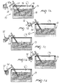
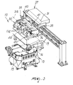
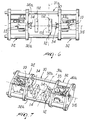
- the apparatus 10 comprises a die-casting machine 11 (shown in Figures 3, 4, 5 and partially shown in Figures 6 and 7 but not in Figures 1 and 2), which will be described hereinafter and with which a corresponding die 12 is to be associated.
- a die-casting machine 11 shown in Figures 3, 4, 5 and partially shown in Figures 6 and 7 but not in Figures 1 and 2
- the die is of the type for front casting and is designated by the reference numeral 12a, while in Figures 2a-2e and 5 the die is of the type for side casting and is designated by the reference numeral 12b.
- the apparatus 10 further comprises means 13 for feeding the molten mass into the casting inlet region 14 of the die 12.
- the inlet region 14 is provided at the parting plane 12 along which the die 12 divides into two die parts 112.
- the feeder means 13 are constituted, in this embodiment, by a pressurized dosing furnace 15, for example of the type for low-pressure casting.
- the pressurized dosing furnace 15, during casting, is functionally connected to the inlet region 14 of the die 12 by means of a corresponding feed channel 16.
- the feed channel 16 is constituted by a heated feed tube 17 that draws below the level of the molten mass 18 that is present inside the pressurized furnace 15.
- the end part 19 of the feed tube 17 that is connected directly to the inlet region 14 is oriented downward, along the direction in which the molten mass is fed from the furnace 15 to the die 12, so as to achieve gravity casting into the die during the tilting of the die.
- the apparatus 10 further comprises means 20 for cooling the die 12 before casting, which are associated with means for distributing a release agent inside the impression (or impressions, if the die is of the type with multiple impressions) formed inside the die.
- the cooling means 20 comprise, for example, a tank 22 filled with cooling liquid (for example water), in which the die parts 112 are immersed by way of movements of the die-casting machine 11.
- cooling liquid for example water
- the tank 22 coincides with the release agent distribution means, since for example graphite (used indeed as a release agent) can be dispersed in the cooling liquid.
- a die-casting machine 11 shown schematically in Figures 3, 4, 5 and partially shown in Figures 6 and 7, comprises a device 30 for opening/closing the molding die 12 and means 35 (described hereinafter) for tilting the die 12 about, in this embodiment, a pair of mutually perpendicular substantially horizontal tilting axes, respectively a first tilting axis 31 a, which is substantially parallel to the parting plane of the die 12, and a second tilting axis 31 b, which is substantially perpendicular to the parting plane of the die 12.
- Rotation about one tilting axis 31 or the other is necessary depending on whether the casting to be performed is of the front or side type.
- the tilting axes 31 are co-planar and pass substantially through the center of the inlet region 14 of the die 12.
- the opening/closing device 30 comprises two mutually opposite closure units 32, of which a first one is fixed and a second one can move with respect to the first one on guiding columns 32a.
- a respective articulation unit 33 is coupled to each closure unit 32.
- the articulation units 33 have, on respective mutually opposite facing ends, flanges 34 for fixing to the die portions 112.
- the articulation unit 33 which is known in principle, allows movements about two mutually perpendicular axes, which are designed to manage accessibility to the die parts 112 and their correct orientation when they are inserted in the tank 22 in order to cool them and wet them with the release agent.
- the device 30 is pivoted about the second tilting axis 31b to an intermediate frame 36.
- the intermediate frame 36 is pivoted to a supporting framework 37 about the first tilting axis 31b.
- the supporting framework 37 is associated with movement means 38, which are constituted by a carriage 39 that can slide in a controlled manner on a horizontal guide 42 that is formed on the beam of a portal 43 that is fixed to the ground.
- the movement means 38 allow the device 30 to move in a linear manner from the region of the tank 22, where the die parts 112 are cooled and the release agent is applied, to the casting region in front of the furnace 15.
- a variation of the movement means 38 can also be constituted by a carousel that rotates the supporting framework 37 about a vertical axis.
- the tilting means 35 comprise a first motor drive, designated schematically by the reference numeral 40, which is arranged on the intermediate frame 36 and allows the rotation of the press 30 about the axis 31b with respect to the intermediate frame 36.
- the first motor drive 40 can be constituted for example by a gearmotor (not designated by a reference numeral in the figures), which is kinematically associated, for example by means of a chain, with a sprocket (both not designated by reference numerals in the figures), which is rigidly coupled to the press 30 and coaxial to the axis 31b, or in any case can be constituted by other movement means of a known electrical or hydraulic type.
- a gearmotor not designated by a reference numeral in the figures
- a sprocket both not designated by reference numerals in the figures
- the tilting means 35 comprise a second motor drive, designated schematically by the reference numeral 41, which is arranged on the supporting framework 37 and acts on the intermediate frame 36 in order to rotate it about the first tilting axis 31a.
- the process for gravity casting in a tilting die consists in distributing release agent onto the walls of the impression (or impressions) formed inside the open die 12.
- the core of the casting (for example a faucet) is inserted in the impression and the die 12 is closed.
- the molten mass is poured into the die 12 through the inlet region 14.
- the tilting motion of the die 14 begins along a preset direction of rotation about a preset tilting axis 31, depending on whether front or side casting is being performed.
- the casting inlet region 14 of the die 12 and the end of the feed tube 17 are moved mutually apart ( Figures 1e and 2e), and a preset solidification time, calculated according to the casting, is allowed to elapse.
- the mold is opened, the casting is extracted and the die parts 112 are moved into the cooling tank 22 (see the die parts 112 shown in broken lines inside the tank 22 in Figures 3 and 4); since graphite is also present inside the tank, the release agent is applied simultaneously with the cooling operation, thus restarting the work cycle.
- the apparatus described above combines the advantages of gravity casting with tilting dies (low costs of the dies and short machine setup times) and the advantages provided by molding apparatuses with low-pressure furnaces (higher quality of the produced casting).
- the materials employed may be any according to requirements and to the state of the art.
Landscapes
- Engineering & Computer Science (AREA)
- Mechanical Engineering (AREA)
- Molds, Cores, And Manufacturing Methods Thereof (AREA)
Applications Claiming Priority (2)
| Application Number | Priority Date | Filing Date | Title |
|---|---|---|---|
| ITPD20030115 | 2003-05-27 | ||
| ITPD20030115 ITPD20030115A1 (it) | 2003-05-27 | 2003-05-27 | Impianto di colata in gravita' con conchiglia di formatura |
Publications (1)
| Publication Number | Publication Date |
|---|---|
| EP1481749A1 true EP1481749A1 (en) | 2004-12-01 |
Family
ID=33105050
Family Applications (1)
| Application Number | Title | Priority Date | Filing Date |
|---|---|---|---|
| EP04012069A Withdrawn EP1481749A1 (en) | 2003-05-27 | 2004-05-21 | Gravity casting apparatus with tilting die and method for gravity casting with tilting die |
Country Status (2)
| Country | Link |
|---|---|
| EP (1) | EP1481749A1 (it) |
| IT (1) | ITPD20030115A1 (it) |
Cited By (8)
| Publication number | Priority date | Publication date | Assignee | Title |
|---|---|---|---|---|
| EP1797980A3 (en) * | 2005-12-13 | 2009-04-15 | IMR S.p.A. | Low-pressure die-casting apparatus |
| JP2010214423A (ja) * | 2009-03-17 | 2010-09-30 | Sukegawa Electric Co Ltd | 電磁ポンプ注湯式鋳型傾斜鋳造装置と方法 |
| CN1806962B (zh) * | 2005-01-18 | 2012-02-29 | 光生铝工业株式会社 | 三维铸造机及三维铸造方法 |
| CN104588625A (zh) * | 2014-12-18 | 2015-05-06 | 济南圣元机械工程有限公司 | 具有倾转动作的重力铸造机及其倾转动作液压控制系统 |
| CN108463298A (zh) * | 2016-01-13 | 2018-08-28 | 库尔特股份有限公司 | 用于铸造的装置 |
| CN110576171A (zh) * | 2019-09-23 | 2019-12-17 | 溧阳市新明机械配件制造有限公司 | 一种砂芯生产用砂模铸造装置 |
| CN110788309A (zh) * | 2019-11-28 | 2020-02-14 | 德林智能科技有限公司 | 一种侧浇式重力浇铸机及其使用方法 |
| CN112091201A (zh) * | 2020-09-09 | 2020-12-18 | 许清珍 | 一种铸造浇注装置 |
Families Citing this family (1)
| Publication number | Priority date | Publication date | Assignee | Title |
|---|---|---|---|---|
| CN116765365A (zh) * | 2021-12-23 | 2023-09-19 | 赵洋 | 一种铝水自动浇铸设备 |
Citations (3)
| Publication number | Priority date | Publication date | Assignee | Title |
|---|---|---|---|---|
| US2195960A (en) * | 1934-08-15 | 1940-04-02 | Morris Engineering Corp | Apparatus for casting metal |
| DE2833569A1 (de) * | 1978-07-31 | 1980-02-28 | Engstfeld Wilh Gmbh & Co | Maschine zum giessen von metallwerkstuecken, insbesondere aus aluminiumlegierungen |
| WO2002055237A1 (en) * | 2001-01-16 | 2002-07-18 | Sintokogio, Ltd. | Gravity type tiltable metal mold casting machine |
-
2003
- 2003-05-27 IT ITPD20030115 patent/ITPD20030115A1/it unknown
-
2004
- 2004-05-21 EP EP04012069A patent/EP1481749A1/en not_active Withdrawn
Patent Citations (3)
| Publication number | Priority date | Publication date | Assignee | Title |
|---|---|---|---|---|
| US2195960A (en) * | 1934-08-15 | 1940-04-02 | Morris Engineering Corp | Apparatus for casting metal |
| DE2833569A1 (de) * | 1978-07-31 | 1980-02-28 | Engstfeld Wilh Gmbh & Co | Maschine zum giessen von metallwerkstuecken, insbesondere aus aluminiumlegierungen |
| WO2002055237A1 (en) * | 2001-01-16 | 2002-07-18 | Sintokogio, Ltd. | Gravity type tiltable metal mold casting machine |
Non-Patent Citations (1)
| Title |
|---|
| PATENT ABSTRACTS OF JAPAN vol. 0186, no. 63 (M - 1723) 14 December 1994 (1994-12-14) * |
Cited By (10)
| Publication number | Priority date | Publication date | Assignee | Title |
|---|---|---|---|---|
| CN1806962B (zh) * | 2005-01-18 | 2012-02-29 | 光生铝工业株式会社 | 三维铸造机及三维铸造方法 |
| EP1797980A3 (en) * | 2005-12-13 | 2009-04-15 | IMR S.p.A. | Low-pressure die-casting apparatus |
| JP2010214423A (ja) * | 2009-03-17 | 2010-09-30 | Sukegawa Electric Co Ltd | 電磁ポンプ注湯式鋳型傾斜鋳造装置と方法 |
| CN104588625A (zh) * | 2014-12-18 | 2015-05-06 | 济南圣元机械工程有限公司 | 具有倾转动作的重力铸造机及其倾转动作液压控制系统 |
| CN108463298A (zh) * | 2016-01-13 | 2018-08-28 | 库尔特股份有限公司 | 用于铸造的装置 |
| CN108463298B (zh) * | 2016-01-13 | 2021-07-06 | 库尔特股份有限公司 | 用于铸造的装置 |
| US11602786B2 (en) | 2016-01-13 | 2023-03-14 | Kurtz Gmbh | Apparatus for casting |
| CN110576171A (zh) * | 2019-09-23 | 2019-12-17 | 溧阳市新明机械配件制造有限公司 | 一种砂芯生产用砂模铸造装置 |
| CN110788309A (zh) * | 2019-11-28 | 2020-02-14 | 德林智能科技有限公司 | 一种侧浇式重力浇铸机及其使用方法 |
| CN112091201A (zh) * | 2020-09-09 | 2020-12-18 | 许清珍 | 一种铸造浇注装置 |
Also Published As
| Publication number | Publication date |
|---|---|
| ITPD20030115A1 (it) | 2004-11-28 |
Similar Documents
| Publication | Publication Date | Title |
|---|---|---|
| CN102223969B (zh) | 以金属熔体浇铸成铸件的方法及装置 | |
| KR101765288B1 (ko) | 정밀주조용 정량주입장치 | |
| MX2013014363A (es) | Distribucion y metodo para moldes para fundicion de metal. | |
| US3907022A (en) | Method of handling and replacing pouring tubes of a continuous casting apparatus | |
| CN108463298B (zh) | 用于铸造的装置 | |
| US2195960A (en) | Apparatus for casting metal | |
| KR101061947B1 (ko) | 다이캐스팅 금형 장치 | |
| JPH0470105B2 (it) | ||
| JP4277265B2 (ja) | 鋳造設備における金型鋳造装置 | |
| US4324392A (en) | Molten metal pouring device | |
| US3218682A (en) | Apparatus for molten metal supply changeover during casting | |
| JPH10286658A (ja) | 連続鋳造機のタンディッシュノズル交換装置 | |
| JP2000326063A (ja) | 流動性の金属で鋳型を充填する方法および装置 | |
| KR102858129B1 (ko) | 경동 주입 중력 주조용 주조 장치 | |
| CN117047039B (zh) | 一种风力发电机高强度机壳铸造方法 | |
| US6520243B1 (en) | Mold riding shot blocker | |
| CN209363584U (zh) | 一种高频离心铸造机 | |
| JPH0217262B2 (it) | ||
| US3670803A (en) | Chill casting machines | |
| CN113145840A (zh) | 铸造用自动化浇注装置及铸造生产线 | |
| JP7252033B2 (ja) | 遠心鋳造機及びその遠心鋳造機におけるブラッキング液の塗布方法 | |
| CN223775965U (zh) | 一种生产切换时间短的连铸机 | |
| CN216176584U (zh) | 一种机床铸件的注模装置 | |
| KR101661978B1 (ko) | 주조장치 및 그 제어방법 | |
| CN221434925U (zh) | 一种金属制品加工浇注装置 |
Legal Events
| Date | Code | Title | Description |
|---|---|---|---|
| PUAI | Public reference made under article 153(3) epc to a published international application that has entered the european phase |
Free format text: ORIGINAL CODE: 0009012 |
|
| AK | Designated contracting states |
Kind code of ref document: A1 Designated state(s): AT BE BG CH CY CZ DE DK EE ES FI FR GB GR HU IE IT LI LU MC NL PL PT RO SE SI SK TR |
|
| AX | Request for extension of the european patent |
Extension state: AL HR LT LV MK |
|
| RIN1 | Information on inventor provided before grant (corrected) |
Inventor name: GIOLO, FABIO |
|
| 17P | Request for examination filed |
Effective date: 20050506 |
|
| AKX | Designation fees paid |
Designated state(s): IT |
|
| REG | Reference to a national code |
Ref country code: DE Ref legal event code: 8566 |
|
| 17Q | First examination report despatched |
Effective date: 20071108 |
|
| GRAP | Despatch of communication of intention to grant a patent |
Free format text: ORIGINAL CODE: EPIDOSNIGR1 |
|
| STAA | Information on the status of an ep patent application or granted ep patent |
Free format text: STATUS: THE APPLICATION IS DEEMED TO BE WITHDRAWN |
|
| 18D | Application deemed to be withdrawn |
Effective date: 20091114 |