EP1481815A1 - Méthode et appareil pour le montage et l'impression à haute vitesse de plaques colorés sur un substrat - Google Patents
Méthode et appareil pour le montage et l'impression à haute vitesse de plaques colorés sur un substrat Download PDFInfo
- Publication number
- EP1481815A1 EP1481815A1 EP20040012713 EP04012713A EP1481815A1 EP 1481815 A1 EP1481815 A1 EP 1481815A1 EP 20040012713 EP20040012713 EP 20040012713 EP 04012713 A EP04012713 A EP 04012713A EP 1481815 A1 EP1481815 A1 EP 1481815A1
- Authority
- EP
- European Patent Office
- Prior art keywords
- sheets
- chips
- station
- printing
- accordance
- Prior art date
- Legal status (The legal status is an assumption and is not a legal conclusion. Google has not performed a legal analysis and makes no representation as to the accuracy of the status listed.)
- Withdrawn
Links
- 238000007639 printing Methods 0.000 title claims abstract description 106
- 238000000034 method Methods 0.000 title claims abstract description 34
- 238000009966 trimming Methods 0.000 claims abstract description 38
- 238000004519 manufacturing process Methods 0.000 claims abstract description 9
- 238000005520 cutting process Methods 0.000 claims description 28
- 239000003973 paint Substances 0.000 claims description 9
- 239000000463 material Substances 0.000 claims description 8
- 230000001360 synchronised effect Effects 0.000 claims description 6
- 238000003848 UV Light-Curing Methods 0.000 claims description 3
- 239000002699 waste material Substances 0.000 claims 1
- 239000000853 adhesive Substances 0.000 description 19
- 230000001070 adhesive effect Effects 0.000 description 19
- 239000003292 glue Substances 0.000 description 4
- 239000013536 elastomeric material Substances 0.000 description 3
- 239000000284 extract Substances 0.000 description 2
- 238000004026 adhesive bonding Methods 0.000 description 1
- 230000000712 assembly Effects 0.000 description 1
- 238000000429 assembly Methods 0.000 description 1
- 239000003086 colorant Substances 0.000 description 1
- 230000008021 deposition Effects 0.000 description 1
- 238000010586 diagram Methods 0.000 description 1
- 238000007599 discharging Methods 0.000 description 1
- 239000003517 fume Substances 0.000 description 1
- 239000000123 paper Substances 0.000 description 1
- 239000011087 paperboard Substances 0.000 description 1
- 230000002093 peripheral effect Effects 0.000 description 1
Images


Classifications
-
- B—PERFORMING OPERATIONS; TRANSPORTING
- B41—PRINTING; LINING MACHINES; TYPEWRITERS; STAMPS
- B41F—PRINTING MACHINES OR PRESSES
- B41F17/00—Printing apparatus or machines of special types or for particular purposes, not otherwise provided for
-
- B—PERFORMING OPERATIONS; TRANSPORTING
- B42—BOOKBINDING; ALBUMS; FILES; SPECIAL PRINTED MATTER
- B42D—BOOKS; BOOK COVERS; LOOSE LEAVES; PRINTED MATTER CHARACTERISED BY IDENTIFICATION OR SECURITY FEATURES; PRINTED MATTER OF SPECIAL FORMAT OR STYLE NOT OTHERWISE PROVIDED FOR; DEVICES FOR USE THEREWITH AND NOT OTHERWISE PROVIDED FOR; MOVABLE-STRIP WRITING OR READING APPARATUS
- B42D1/00—Books or other bound products
-
- B—PERFORMING OPERATIONS; TRANSPORTING
- B42—BOOKBINDING; ALBUMS; FILES; SPECIAL PRINTED MATTER
- B42D—BOOKS; BOOK COVERS; LOOSE LEAVES; PRINTED MATTER CHARACTERISED BY IDENTIFICATION OR SECURITY FEATURES; PRINTED MATTER OF SPECIAL FORMAT OR STYLE NOT OTHERWISE PROVIDED FOR; DEVICES FOR USE THEREWITH AND NOT OTHERWISE PROVIDED FOR; MOVABLE-STRIP WRITING OR READING APPARATUS
- B42D15/00—Printed matter of special format or style not otherwise provided for
-
- B—PERFORMING OPERATIONS; TRANSPORTING
- B44—DECORATIVE ARTS
- B44D—PAINTING OR ARTISTIC DRAWING, NOT OTHERWISE PROVIDED FOR; PRESERVING PAINTINGS; SURFACE TREATMENT TO OBTAIN SPECIAL ARTISTIC SURFACE EFFECTS OR FINISHES
- B44D3/00—Accessories or implements for use in connection with painting or artistic drawing, not otherwise provided for; Methods or devices for colour determination, selection, or synthesis, e.g. use of colour tables
- B44D3/003—Methods or devices for colour determination, selection or synthesis, e.g. use of colour tables
-
- Y—GENERAL TAGGING OF NEW TECHNOLOGICAL DEVELOPMENTS; GENERAL TAGGING OF CROSS-SECTIONAL TECHNOLOGIES SPANNING OVER SEVERAL SECTIONS OF THE IPC; TECHNICAL SUBJECTS COVERED BY FORMER USPC CROSS-REFERENCE ART COLLECTIONS [XRACs] AND DIGESTS
- Y10—TECHNICAL SUBJECTS COVERED BY FORMER USPC
- Y10T—TECHNICAL SUBJECTS COVERED BY FORMER US CLASSIFICATION
- Y10T156/00—Adhesive bonding and miscellaneous chemical manufacture
- Y10T156/17—Surface bonding means and/or assemblymeans with work feeding or handling means
- Y10T156/1702—For plural parts or plural areas of single part
- Y10T156/1744—Means bringing discrete articles into assembled relationship
- Y10T156/1751—At least three articles
- Y10T156/1754—At least two applied side by side to common base
- Y10T156/1756—Plural ranks
Definitions
- This invention relates to a method of and an apparatus for mounting and printing on swatches or colored chips on sheets.
- sheets are moved intermittently through a machine to receive a number of colored chips thereon with the sheets being stopped at adhesive station where a rotating adhesive cylinder applies adhesive at the chip receiving locations.
- a rotating adhesive cylinder applies adhesive at the chip receiving locations.
- various colored chips are severed from colored ribbons and are applied by a swatch applying cylinder to the respective adhesive spots to adhere the chips to the sheet.
- the chips are adhered close to printing on the sheet or in a preprinted box on the sheet and the chips are placed very precisely on the sheet particularly with respect to the printing.
- the sheets may vary from relatively thin paper that is about .0035 to 0.0040 inch thick as well as to paper board that is about 0.008 to 0.010 inch thick.
- the swatches vary in area, thickness of the swatch material and the pattern of their deposition on a sheet.
- a U.S. Patent No. 6,086,694 discloses a method and apparatus for the manufacture of chip bearing sheets with the swatches being adhered to a web which is usually preprinted and which is cut into sheets after all the swatches have been applied to the web for a given sheet length.
- the sheets leaving one of the machines described above were usually in the form of either rectangular or square shapes and if it was desired to change the shape of one or more of the chips, the sheets would taken to an off-line die cutting system which would remove the excess scrap material about the desired shape. That is the die cutting system had dies to cut the chips to provide curves, circles, arcs, etc. on the chip with the excess material cut from the rectangular portion of the sheet being scrap and removed.
- the chips are oversized and at least some of the oversized chips are trimmed at a on-line trimming station which trims the chips to size.
- the trimmed material which is scrap, then is removed by a vacuum system which extracts the scrap.
- the embodiment illustrated hereinafter there is also provided an in-line folder which automatically folds the sheets.
- the chips are applied and adhered to discrete sheets which are pushed forwardly through the chip applying station and into a printing station where the chips are also pushed by pushers engaging the trailing end of the sheet through the printing station where a printer prints indicia on the outer surface of the colored chips.
- a printer prints indicia on the outer surface of the colored chips.
- the chips are spaced axially with respect to the axis of the printing cylinder which has strips of elastomeric material between raised printing surfaces to form a nip with an underlying anvil roller to hold the sheet at locations closed adjacent the raised printing surfaces to prevent the smudging or smearing of the ink being printed on the chips.
- UV ink it is preferred to print on the chips with UV ink at multiple stations with a UV curing device for applying UV energy to the ink to cure the same following the printing operation.
- the chips are sized and often some of the chips are formed with a curved circle or arc or the like at a die cutting station wherein an outer portion of the chip that is not adhered to the underlying sheet or web is severed and is removed by a vacuum after having been severed.
- the scrap outer portion of the chip being cut at the die station is adhered to the die cutting cylinder for a short distance as it rotates away from the nip and then another vacuum extracts the scrap from the printing cylinder preferably with a release of the vacuum within the die cutting cylinder.
- a positive blast of air is applied to push the scrap from the cylinder and into the extracting pipe which has a vacuum to convey the scrap away from the cylinder.
- a method and apparatus mounting color chip swatches on a sheet, feeding the sheet forwardly into a printing station, printing on the chips while they are traveling in line, and trimming the chips to size by an in-line trimmer at a trimming station.
- the swatches and sheets are aligned for travel in a longitudinal direction and are aligned in a transverse direction and are traveling at synchronized speeds of travel through the respective swatch applying station, the printing station and the trimming station.
- an in-line folding station is also aligned with the other machine at the other stations with its speed of folding synchronized in order to receive the sheets with printed and trimmed swatches and to automatically fold these sheets to provide folded sheets with printed and trimmed swatches thereon.
- an air stream such as a vacuum conveying system automatically removes scrap cut from the trimmed swatches and/or trimmed sheets.
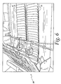
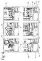
- FIG. 7-9 comprises a method and apparatus for making chip or swatch-bearing sheets 10 such as cards having color chips with printings thereon and further comprises a base sheet or card 10a bearing an array of individually colored chips or swatches 12 of various sizes as seen in FIGS. 7-9.
- the card 10 illustrated in FIGS. 7-9 has photographs 14a-14f.
- FIGS. 7-9 there are six photographs 14a-14f each of which has rectangular colored chips 12 located beneath a respective picture to show the colors that are used or are available for the photograph of rooms or the exterior of the home depicted in these figures.
- the paint chips are provided with identifying indicia or other forms of indicia 20 (FIGS. 8 and 8A) thereon which is printed on the chips at an in-line machine or printing station 22 of the apparatus and which follows the mounting station as will be described in detail hereinafter.
- identifying indicia or other forms of indicia 20 FIGS. 8 and 8A
- Subsequent to being printed upon the chips and the card are preferably sized such as by having rounded corners 23 on the lower outer edges of the lower two paint chips as best seen in FIG. 9.
- the chips are cut to size by a die cutting station or trimming station 24 (FIG.
- the sheet is usually preprinted with printed matter such as photographs 14 or printed material for identification of the goods which are to be painted with the color. It is preferred to print the color identification indicia directly onto the top surface of the swatch at the printing station. In some instances, the color identifying information is preprinted on the sheet and the swatch is positioned precisely within the box without covering any side of the box and without any subsequent printing on the swatch at the printing station 22.
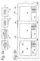
- the chips 12 are adhered to the sheets by spots 28 of glue or adhesive which is applied at an adhesive or gluing station 30 to form the adhesive spots 28 shown in FIG. 1a which are located on the sheet beneath the respective photographs 14a, 14b and 14c.
- the adhesive spots Preferably have shape similar to the final size and shape of the swatch with the spot of adhesives having rounded corners 28b as best seen in FIG. 1a.
- rectangular swatches are applied at the mounting station 15 and they have not been sized or cut yet.
- these rectangularly shaped swatches will have a scrap portion cut therefrom and this scrap portion is not adhered to the sheet by any adhesive 28 so that it can be readily removed from the sheet while the remaining portion is adhered to the sheet by the glue spots 28.
- the chips are usually oversized relative to the adhesive spots if they are to be cut at the die cutting station 24 and reduced in size with the unadhered scrap being removed by a vacuum.
- the synchronized speed of travel is obtained by traveling the sheets at a constant velocity by conveyors or feed rollers through the respective machines while print means or heads, trimmer dies, folders, etc. are timed to perform its cyclical operation on each sheet during the time period the sheet and swatch thereon are at that machine.
- print means or heads, trimmer dies, folders, etc. are timed to perform its cyclical operation on each sheet during the time period the sheet and swatch thereon are at that machine.
- print means or heads, trimmer dies, folders, etc. are timed to perform its cyclical operation on each sheet during the time period the sheet and swatch thereon are at that machine.
- a synchronizing mechanical system or shaft may connect the respective machines at the respective stations or electronic systems may be used to synchronize the feed of sheet travel through each of the respective stations.
- the in-line folding station is aligned to receive the printed and trimmed swatches on the sheets 10 to fold the sheets as they continue to travel at a constant velocity from the
- the swatches are aligned in the longitudinal and in transverse directions on the sheet therefor, the printing means or heads are aligned longitudinally and transversely with the swatches to be printed thereby, the trimming dies are aligned longitudinal and transversely to cut the swatches to trim them, and the folding devices are aligned longitudinally and transversely with respect to fold line positions or areas on the swatch bearing sheets.
- the speed of each in-line operation is synchronized to the constant throughout velocity of the sheets 10 traveling through the in-line system.
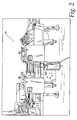
- a base sheet 10a is a stripped from a tray or bin holding a plurality of sheets by a sheet feeding means 34 which delivers the base sheet to a first conveyor 36 which has a plurality of pushers 37 mounted on a chain 38 to push the sheet at the trailing edge thereof to and through the adhesive applying station 30.
- a sheet feeding means 34 which delivers the base sheet to a first conveyor 36 which has a plurality of pushers 37 mounted on a chain 38 to push the sheet at the trailing edge thereof to and through the adhesive applying station 30.
- rotating adhesive the applying cylinders 39 apply the adhesive spots 28 (FIG. 1B) to each of the swatch receiving locations on the base sheet 10a.
- the base sheets then are fed forwardly from the adhesive applying station in timed relationship by a second conveyor 40 having pushers 41 similar to the pushers 37 to push the trailing edge of the sheet into and through a swatch forming and applying station 42 at which individual colored ribbons are unwound from a ribbon supply 44 having a plurality of colored ribbons each wound in a reel.
- the reels are fed forwardly to unwind the ribbons which are cut to form the color chips 12 by a severing means 46.
- the color ribbons are severed by a cutting blade 50 and an anvil blade 52 which pinches off a row of individual swatches from the respective ribbons which are then transferred and pressed by a transfer roller 56 onto the previously applied glue spots 28 on the base sheet 10a thereby adhering and affixing the chips to the underlying base sheet 10.
- the colored chips 12 thus are adhered to and positioned on the base sheets 10a in relationship to the photographs 14 and any other printing and indicia on the sheets at precise positions when leaving the mounting machine or station 15.
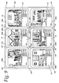
- the sheets are delivered and travel at a predetermined speed as determined by the second conveyor 40 which delivers the sheets 10 with the chips 12 thereon to an in-feed conveyor 58 located at the printing machine 22.
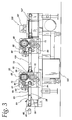
- the in-feed conveyor 58 (FIG. 3) has an endless belt or chain mounted between a rearward sprocket 60 and a forward sprocket 61 for endless travel about a path relative to an in-feed supporting table or surface 63 on which slide the sheets 10.
- the endless belt 59 has the usual upstanding lugs or pusher fingers 64 which push the sheets forwardly along a straight or horizontal path in a continuous travel mode into and through a nip 65 of a printer 66.
- the illustrated printer 66 comprises an upper plate cylinder 68 rotatable about a horizontally disposed upper support shaft 73 for the plate cylinder 68.
- the sheets 10 travel beneath the plate cylinder 68 and across the top of an anvil roller 72 mounted on a horizontally parallel extending support shaft 70.
- the sheets 10 have chips thereon of varying thickness due to the amount of paint thereon. Some paints are made with a thicker coat than other paints and thus form a thicker chip than other chips of a different color. Also there is an underlying adhesive spot 28 for each chip, which is again raising the chip above the upper surface of the base sheet 10a.
- the printing apparatus should be capable of printing on varying surfaces of chips at different heights.
- the printing plates 84 on the plate cylinder be flexible and made of an elastomeric material or other compressible material.
- the particular printing plates are spaced actually and circumferentially about the plate cylinder so that each rotation of the plate cylinder there will be a printing applied only to the locations of the chips and not outside of the chips.
- resilient strips 85 As best seen in FIGS.
- the preferred strips 85 are made of an elastomeric material and are attached to the surface of the plate cylinder by an adhesive or fasteners.
- the particular system shown in FIG. 3 includes an analox system comprising an analox roller 90 which has space circumferential openings thereon to receive ink from a ink metering roller 92 rotatable about a horizontal axis.
- the ink is fed in a conventional manner from an ink reservoir by the ink metering roll to the analox roller which applies the ink to the flexible printing plates 84 on the rotating plate cylinder 68.
- the plate cylinder, anvil roller, analox roller, and ink meeting roller are driven by a common timing chain 94 which is also meshed with and driven by conveyor sprocket 61 for the in-feed conveyor 38 so that the timing of the plate cylinder and anvil roller to the movement of the sheets being pushed by the pushers is being synchronized to cause the printing operation to print on top of the respective colored chips at the precise location desired.
- the ink being used is a UV curable ink which passes by a radiant UV source 100 which exerts energy in the UV range to quickly drive the ink.
- the UV source comprises a UV lamp assembly 101 having enclosed lamps positioned closely adjacent the UV ink on the chips at the discharge end of the printing station 22.
- a UV power supply 102 is located beneath and between first and second printing assemblies and beneath an in-feed pusher conveyor 105 for the second printing assembly that is identical to the first printing assembly and hence will not be described again.
- the pusher in-feed conveyor is similar to the in-feed conveyor 58 and hence it will not be described again in detail.
- a conveyor 107 conveys the printed chips 12 through the UV station to assure that the ink is dry as it leaves the printing station and is delivered to the trimming station. Beneath the UV lamp assembly is disposed a exhaust duct 100 as best seen in FIG. 3 for conveying away any fumes from the UV ink as it is being cured.
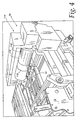
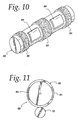
- the chips 12 are applied to adhesive spots 28 (FIG. 1B) and then are later cut to their final size and shape at the trimming station 24 by a flexible die 110 mounted on a rotating die cutter cylinder 112 mounted in the die cutting machine 114.
- a flexible die 110 mounted on a rotating die cutter cylinder 112 mounted in the die cutting machine 114.
- One problem with this approach is the removal of the scrap which is cut from the chips 12 and/or photographs, herein illustrated as being rounded corners 28b.
- the scrap is preferably kept adhered to the rotating cylinder 112 by a negative, vacuum pressure from inside the cylinder until the cylinder rotates away from the die cut nip and into a scrap removal station at which is the inlet of a vacuum scrap pipe located with an inlet end closely adjacent the surface of the die cut cylinder.
- the internal vacuum pressure in the die cutting cylinder is then switched by a valve to a positive air force to push the scrap away and into the vacuum pipe for transport by air to a remote collection point away from the rotating cylinder 112 and preferably away from the die cutting machine 114.
- the system produces a double wide stream of two cards and it is the die cutting station that cards are separated from one another.
- Each card has three sections and are joined to an adjacent section at a line 120 and 120a which will become fold lines when the card is folded subsequently in the in-line folding station 26.
- the card In addition to cutting the rounded corners 23 on the chips, as shown in FIG. 9, the card itself is cut with rounded corners 125 at all four corners of each section.
- the cut material defines a V-shaped space 127 between sections; as shown in FIG. 9.
- the cards can be formed without the rounded corners or have other shapes with a change of the flexible cutting dies on the die cutting cylinder.
- other die cutting machines using flat beds or systems can be used; the continuous in-line feeding used in this embodiment to use a continuously traveling conveyor 129 is preferred for higher production speeds.
- the respective rows of cards leaving the trimming station 24 are carried in two side-by-side streams on an in-feed conveyor into an automatic folding machine 135 at the folding station 26.
- one end section such as the section 128a is folded back over the top of the center section 128b and the other end section 128c such as the trailing end section 128c is folded over the top of the leading end section 128a to provide a three ply folded color card which is seen (FIG. 6) leaving in two streams of cards from the folding station 26.
- the holder card is now ready to be boxed and shipped.
Landscapes
- Business, Economics & Management (AREA)
- Engineering & Computer Science (AREA)
- Educational Administration (AREA)
- Educational Technology (AREA)
- Making Paper Articles (AREA)
Applications Claiming Priority (2)
| Application Number | Priority Date | Filing Date | Title |
|---|---|---|---|
| US47417203P | 2003-05-29 | 2003-05-29 | |
| US474172P | 2003-05-29 |
Publications (1)
| Publication Number | Publication Date |
|---|---|
| EP1481815A1 true EP1481815A1 (fr) | 2004-12-01 |
Family
ID=33131957
Family Applications (1)
| Application Number | Title | Priority Date | Filing Date |
|---|---|---|---|
| EP20040012713 Withdrawn EP1481815A1 (fr) | 2003-05-29 | 2004-05-28 | Méthode et appareil pour le montage et l'impression à haute vitesse de plaques colorés sur un substrat |
Country Status (4)
| Country | Link |
|---|---|
| US (2) | US7007601B2 (fr) |
| EP (1) | EP1481815A1 (fr) |
| AU (1) | AU2004202285A1 (fr) |
| CA (1) | CA2468002C (fr) |
Families Citing this family (9)
| Publication number | Priority date | Publication date | Assignee | Title |
|---|---|---|---|---|
| JP2004291493A (ja) * | 2003-03-27 | 2004-10-21 | Brother Ind Ltd | 印刷装置、印刷システム及び印刷方法 |
| US7718020B2 (en) * | 2005-09-12 | 2010-05-18 | Color Communications, Inc. | Method and apparatus for manufacture and inspection of swatch bearing sheets using a vacuum conveyor |
| US20080092457A1 (en) * | 2006-03-31 | 2008-04-24 | Marilyn Malone | Articles for Selecting Colors for Surfaces |
| KR100774523B1 (ko) | 2006-06-30 | 2007-11-08 | 주식회사 스쿨룩스 | 의류 식별부재의 가공장치 |
| US7832440B2 (en) * | 2007-01-15 | 2010-11-16 | Masco Corporation | Machine and method for applying pressure sensitive sample chips to a card |
| JP4320044B2 (ja) * | 2007-12-17 | 2009-08-26 | 株式会社塚谷刃物製作所 | フレキシブルダイ |
| DE102008051061B3 (de) * | 2008-10-09 | 2010-04-08 | Mr Etikettiertechnik Gmbh & Co. Kg | Etikettiervorrichtung |
| WO2012170623A2 (fr) | 2011-06-07 | 2012-12-13 | Valspar Sourcing, Inc. | Revêtement à base d'eau pour échantillonnage de couleur |
| CN103963433B (zh) * | 2014-05-07 | 2016-01-27 | 湖北京山轻工机械股份有限公司 | 一种印刷生产线 |
Citations (5)
| Publication number | Priority date | Publication date | Assignee | Title |
|---|---|---|---|---|
| FR805203A (fr) * | 1935-04-29 | 1936-11-14 | Anciens Ets Skoda | Procédé et dispositif pour découper des bandes de liège et analogues pour embouchures, et pour les fixer sur le ruban de papier à cigarettes en mouvement |
| US3919039A (en) * | 1972-09-12 | 1975-11-11 | Polytex Ag | Apparatus for making swatch cards |
| US4061521A (en) * | 1976-07-19 | 1977-12-06 | Color Communications, Inc. | Method and apparatus for manufacture of swatch bearing sheets |
| US6030481A (en) * | 1994-12-19 | 2000-02-29 | Color Communications, Inc. | Method and apparatus for manufacture of swatch bearing sheets |
| US6086694A (en) * | 1997-04-01 | 2000-07-11 | Stanley Lerner | High speed web machine |
Family Cites Families (9)
| Publication number | Priority date | Publication date | Assignee | Title |
|---|---|---|---|---|
| US1644044A (en) * | 1925-05-28 | 1927-10-04 | David A Urie | Machine for attaching color chips to cards |
| US1943390A (en) * | 1930-10-13 | 1934-01-16 | Oser Alfred | Apparatus for mounting samples on cards and the like |
| US2525612A (en) * | 1950-03-28 | 1950-10-10 | James A Mckay | Color card machine |
| US4457718A (en) * | 1981-02-12 | 1984-07-03 | Color Communications, Inc. | Color display product |
| US4379696A (en) * | 1981-02-12 | 1983-04-12 | Color Communications, Inc. | Latex mylar chip |
| US5313884A (en) * | 1992-04-02 | 1994-05-24 | Color Communications, Inc. | Reverse roller coating apparatus |
| CA2097980A1 (fr) * | 1992-06-16 | 1993-12-17 | Stanley Lerner | Methode et appareil de pose d'echantillons sur une feuille support |
| JP4148352B2 (ja) * | 2002-07-11 | 2008-09-10 | 株式会社鈴木松風堂 | 色見本製造装置 |
| JP2004198857A (ja) * | 2002-12-20 | 2004-07-15 | Futagami Tekkosho:Kk | 見本貼着装置 |
-
2004
- 2004-05-21 CA CA2468002A patent/CA2468002C/fr not_active Expired - Lifetime
- 2004-05-25 US US10/852,778 patent/US7007601B2/en not_active Expired - Lifetime
- 2004-05-26 AU AU2004202285A patent/AU2004202285A1/en not_active Abandoned
- 2004-05-28 EP EP20040012713 patent/EP1481815A1/fr not_active Withdrawn
-
2006
- 2006-01-23 US US11/337,710 patent/US20060117969A1/en not_active Abandoned
Patent Citations (5)
| Publication number | Priority date | Publication date | Assignee | Title |
|---|---|---|---|---|
| FR805203A (fr) * | 1935-04-29 | 1936-11-14 | Anciens Ets Skoda | Procédé et dispositif pour découper des bandes de liège et analogues pour embouchures, et pour les fixer sur le ruban de papier à cigarettes en mouvement |
| US3919039A (en) * | 1972-09-12 | 1975-11-11 | Polytex Ag | Apparatus for making swatch cards |
| US4061521A (en) * | 1976-07-19 | 1977-12-06 | Color Communications, Inc. | Method and apparatus for manufacture of swatch bearing sheets |
| US6030481A (en) * | 1994-12-19 | 2000-02-29 | Color Communications, Inc. | Method and apparatus for manufacture of swatch bearing sheets |
| US6086694A (en) * | 1997-04-01 | 2000-07-11 | Stanley Lerner | High speed web machine |
Also Published As
| Publication number | Publication date |
|---|---|
| CA2468002A1 (fr) | 2004-11-29 |
| AU2004202285A1 (en) | 2004-12-16 |
| US7007601B2 (en) | 2006-03-07 |
| CA2468002C (fr) | 2012-09-25 |
| US20040237811A1 (en) | 2004-12-02 |
| US20060117969A1 (en) | 2006-06-08 |
Similar Documents
| Publication | Publication Date | Title |
|---|---|---|
| AU673526B2 (en) | Linerless label printer applicator | |
| AU715798B2 (en) | Applying a tactilely distinguishable marking on an article | |
| JP3233636B2 (ja) | 担体から版を被転写体上に転写する方法および装置 | |
| US10543674B2 (en) | Device for treating substrates | |
| US4959115A (en) | Method of producing blocks of self-adhesive labels or the like and of applying the labels to a body | |
| US20010040330A1 (en) | Booklet forming method and apparatus | |
| EP0465256B1 (fr) | Appareil pour transférer des bandes de matériel sur une bande de papier | |
| CN1077065C (zh) | 生产印花带状标签及将其贴到香烟盒上的方法和设备 | |
| US20120275881A1 (en) | Machine for producing books, in particular photo books and/or illustrated books | |
| EP0537145A1 (fr) | Procede de production d'un paquet imprime destine a une distribution massive. | |
| US4061521A (en) | Method and apparatus for manufacture of swatch bearing sheets | |
| US7934529B2 (en) | Method and apparatus for manufacture and inspection of swatch bearing sheets using a vacuum conveyor | |
| CA2468002C (fr) | Montage et impression a haute vitesse de coupons colores sur une feuille | |
| JPH07112753B2 (ja) | 自己接着性付箋紙ブロツクを造るための方法および装置 | |
| JP2003519017A (ja) | ボンド紙を切断する方法 | |
| US6286871B1 (en) | Pads of embossed, self-stick paper and process and apparatus for making same | |
| US6406244B1 (en) | Stack of sheets with repositionable adhesive alternating between opposite edges and containing one or more sheets different from other sheets | |
| GB2200343A (en) | Forming shingled stream from continuous web | |
| EP0587322B1 (fr) | Procédé et système d'impression pour produire des documents constitués de plusieurs parties | |
| US3937452A (en) | Method and apparatus for manufacturing continuous form sets | |
| AU735850B2 (en) | Stack of sheets with repositionable adhesive alternating between opposite edges and containing one or more sheets different from other sheets | |
| CN220720569U (zh) | 一种rfid平张纸电子标签复合机 | |
| GB2072133A (en) | Machine and method for producing weather-proof multi-leaf shipping forms | |
| US3707424A (en) | Adjustable label form slitter for addressing machines | |
| CN115742447A (zh) | 一种纸箱生产工艺 |
Legal Events
| Date | Code | Title | Description |
|---|---|---|---|
| PUAI | Public reference made under article 153(3) epc to a published international application that has entered the european phase |
Free format text: ORIGINAL CODE: 0009012 |
|
| AK | Designated contracting states |
Kind code of ref document: A1 Designated state(s): AT BE BG CH CY CZ DE DK EE ES FI FR GB GR HU IE IT LI LU MC NL PL PT RO SE SI SK TR |
|
| AX | Request for extension of the european patent |
Extension state: AL HR LT LV MK |
|
| 17P | Request for examination filed |
Effective date: 20050601 |
|
| AKX | Designation fees paid |
Designated state(s): DE FR GB IT NL |
|
| 17Q | First examination report despatched |
Effective date: 20070807 |
|
| STAA | Information on the status of an ep patent application or granted ep patent |
Free format text: STATUS: THE APPLICATION IS DEEMED TO BE WITHDRAWN |
|
| 18D | Application deemed to be withdrawn |
Effective date: 20101201 |