EP1481863A1 - Système hydraulique de freinage à deux circuits pour véhicules - Google Patents
Système hydraulique de freinage à deux circuits pour véhicules Download PDFInfo
- Publication number
- EP1481863A1 EP1481863A1 EP04101651A EP04101651A EP1481863A1 EP 1481863 A1 EP1481863 A1 EP 1481863A1 EP 04101651 A EP04101651 A EP 04101651A EP 04101651 A EP04101651 A EP 04101651A EP 1481863 A1 EP1481863 A1 EP 1481863A1
- Authority
- EP
- European Patent Office
- Prior art keywords
- brake
- vehicle
- circuit
- auxiliary pump
- pressure
- Prior art date
- Legal status (The legal status is an assumption and is not a legal conclusion. Google has not performed a legal analysis and makes no representation as to the accuracy of the status listed.)
- Granted
Links
- 239000012530 fluid Substances 0.000 claims abstract description 29
- 238000000034 method Methods 0.000 claims abstract description 5
- 238000011144 upstream manufacturing Methods 0.000 claims description 5
- 230000009977 dual effect Effects 0.000 abstract 1
- 230000006870 function Effects 0.000 description 4
- 230000000712 assembly Effects 0.000 description 1
- 238000000429 assembly Methods 0.000 description 1
- 230000009286 beneficial effect Effects 0.000 description 1
- 230000001934 delay Effects 0.000 description 1
- 238000010586 diagram Methods 0.000 description 1
- 230000000694 effects Effects 0.000 description 1
- 230000003203 everyday effect Effects 0.000 description 1
- 230000002349 favourable effect Effects 0.000 description 1
- 230000003993 interaction Effects 0.000 description 1
- 230000008092 positive effect Effects 0.000 description 1
- 238000005086 pumping Methods 0.000 description 1
- 230000006641 stabilisation Effects 0.000 description 1
- 238000011105 stabilization Methods 0.000 description 1
Images

Classifications
-
- B—PERFORMING OPERATIONS; TRANSPORTING
- B60—VEHICLES IN GENERAL
- B60T—VEHICLE BRAKE CONTROL SYSTEMS OR PARTS THEREOF; BRAKE CONTROL SYSTEMS OR PARTS THEREOF, IN GENERAL; ARRANGEMENT OF BRAKING ELEMENTS ON VEHICLES IN GENERAL; PORTABLE DEVICES FOR PREVENTING UNWANTED MOVEMENT OF VEHICLES; VEHICLE MODIFICATIONS TO FACILITATE COOLING OF BRAKES
- B60T8/00—Arrangements for adjusting wheel-braking force to meet varying vehicular or ground-surface conditions, e.g. limiting or varying distribution of braking force
- B60T8/32—Arrangements for adjusting wheel-braking force to meet varying vehicular or ground-surface conditions, e.g. limiting or varying distribution of braking force responsive to a speed condition, e.g. acceleration or deceleration
- B60T8/34—Arrangements for adjusting wheel-braking force to meet varying vehicular or ground-surface conditions, e.g. limiting or varying distribution of braking force responsive to a speed condition, e.g. acceleration or deceleration having a fluid pressure regulator responsive to a speed condition
- B60T8/40—Arrangements for adjusting wheel-braking force to meet varying vehicular or ground-surface conditions, e.g. limiting or varying distribution of braking force responsive to a speed condition, e.g. acceleration or deceleration having a fluid pressure regulator responsive to a speed condition comprising an additional fluid circuit including fluid pressurising means for modifying the pressure of the braking fluid, e.g. including wheel driven pumps for detecting a speed condition, or pumps which are controlled by means independent of the braking system
- B60T8/404—Control of the pump unit
- B60T8/4054—Control of the pump unit involving the delivery pressure control
-
- B—PERFORMING OPERATIONS; TRANSPORTING
- B60—VEHICLES IN GENERAL
- B60T—VEHICLE BRAKE CONTROL SYSTEMS OR PARTS THEREOF; BRAKE CONTROL SYSTEMS OR PARTS THEREOF, IN GENERAL; ARRANGEMENT OF BRAKING ELEMENTS ON VEHICLES IN GENERAL; PORTABLE DEVICES FOR PREVENTING UNWANTED MOVEMENT OF VEHICLES; VEHICLE MODIFICATIONS TO FACILITATE COOLING OF BRAKES
- B60T8/00—Arrangements for adjusting wheel-braking force to meet varying vehicular or ground-surface conditions, e.g. limiting or varying distribution of braking force
- B60T8/32—Arrangements for adjusting wheel-braking force to meet varying vehicular or ground-surface conditions, e.g. limiting or varying distribution of braking force responsive to a speed condition, e.g. acceleration or deceleration
- B60T8/34—Arrangements for adjusting wheel-braking force to meet varying vehicular or ground-surface conditions, e.g. limiting or varying distribution of braking force responsive to a speed condition, e.g. acceleration or deceleration having a fluid pressure regulator responsive to a speed condition
- B60T8/48—Arrangements for adjusting wheel-braking force to meet varying vehicular or ground-surface conditions, e.g. limiting or varying distribution of braking force responsive to a speed condition, e.g. acceleration or deceleration having a fluid pressure regulator responsive to a speed condition connecting the brake actuator to an alternative or additional source of fluid pressure, e.g. traction control systems
- B60T8/4809—Traction control, stability control, using both the wheel brakes and other automatic braking systems
- B60T8/4827—Traction control, stability control, using both the wheel brakes and other automatic braking systems in hydraulic brake systems
- B60T8/4863—Traction control, stability control, using both the wheel brakes and other automatic braking systems in hydraulic brake systems closed systems
- B60T8/4872—Traction control, stability control, using both the wheel brakes and other automatic braking systems in hydraulic brake systems closed systems pump-back systems
Definitions
- the invention relates to a hydraulic dual-circuit vehicle brake system a two-circuit master brake cylinder with brake fluid reservoir, with one Anti-lock device, the brake pressure modulation valve assemblies and has a return pump for each brake circuit, and with an automatic one Braking device that interacts with the anti-lock device and their return pump, the vehicle movement independent of the driver and can brake and / or stabilize individually for each wheel, as well as with an electric motor driven auxiliary pump for pumping Brake fluid to inlet valves of the wheel brake cylinders at least one Brake circuit, the pressure supplied by the auxiliary pump essential below the maximum that can be generated by means of the master brake cylinder Pressure.
- DE 42 32 311 C1 directed.
- the invention further relates to a method for braking a Motor vehicle using a driver assistance system, the vehicle with a suitably designed hydraulic dual-circuit braking system Is provided.
- Modern brake systems for motor vehicles contain a specialist also known under the name ESP (or DSC) driving dynamics control, that with the for a well-known anti-lock control (ABS) existing components works.
- This Driving dynamics control can cause a vehicle to skid Stabilize targeted braking interventions, the driver-independent Brake pressure build-up from the aforementioned return pumps, which originally were only intended for the anti-lock control system.
- An intermediate level of development also known to the person skilled in the art hydraulic vehicle brake system with vehicle dynamics control included one So-called precharge pump, which measures the dynamics of the pressure build-up with active driving dynamics control should improve especially at low temperatures.
- the pre-charge pump only generated a maximum pressure of 20 bar and was on designed a large volume.
- So-called driver assistance systems for example vehicle speed control
- ACC is an autonomous, i.e. driver-independent Require brake intervention.
- the driver of the Vehicle a desired driving speed that the vehicle under Taking into account the traffic ahead automatically tries.
- the brake system should be in the Be able to automatically set a certain delay in the requested Generate dynamics and quality, with quality essential here higher demands are made than with interventions by vehicle dynamics controllers. While the latter are only active in emergencies Brake interventions by driver assistance systems in everyday situations are very great often, which is why the driver has significantly higher demands here braking is more comfortable than in few emergency situations.
- An autonomous braking intervention by a driver assistance system can be carried out in accordance with the known prior art in different ways.
- the driving dynamics control or the associated system of the Anti-lock device also for building brake pressure for the Driver assistance system used, however, is the existing return pump for completely different requirements than for an autonomous one Brake intervention designed.
- This return pump can handle high pressures generate, but has only a low dynamic, and has one poor controllability in the low pressure range.
- the pressure builds up discontinuous and with the usual wiring on the front axle and Rear axle of the motor vehicle at different heights.
- Beneficial at This concept is the control of the return pump by the Control unit that adopts driving dynamics control, so that there is none for this additional components are required. So this solution can be relative be implemented inexpensively.
- a desired meterable autonomous, i.e. driver-independent brake intervention can alternatively also by means of a controllable vacuum booster generated, but this is complex and expensive. He faces the standard braking device produced in millions of units completely new development. The higher degree of complexity affects disadvantageous on the robustness and reliability of the braking device.
- One advantage of this solution is its suitability for all applications an autonomous brake intervention, for example also for the high dynamic and Automatic cruise control deceleration requirements with stop & go function or automatic accident avoidance.
- a third option for autonomous brake intervention by a driver assistance system represent the so-called brake-by-wire systems, of which so far only the electro-hydraulic principle in small quantities is produced.
- Such a so-called EMS system is extremely complex and complex and unfavorable in terms of the required space and clearly heavier than the other vehicle braking systems mentioned.
- the solution to this problem is characterized in that the auxiliary pump is designed in such a way and the electric motor driving the auxiliary pump is controllable in such a way that the auxiliary pump for driver-independent brake interventions by a driver assistance system, starting from an essentially depressurized state on the wheel brake cylinders of at least one brake circuit, provides a continuously increasing brake fluid pressure up to a maximum value of the order of 25 bar to 45 bar.
- a specially designed auxiliary pump in an otherwise usual two-circuit vehicle brake system with anti-lock device as well as driving dynamics control i.e. in a so-called ESP braking system (or also DSC brake system) provided.
- This auxiliary pump should be able to maintain a pressure level in the order of 25 bar 45 bar to be able to build up to the present dynamic requirements to do justice to, and thus without the addition of the aforementioned Return pump a dynamic braking of the vehicle up to To be able to achieve a standstill. It also drives this pump Electric motor sufficiently controllable to start from essentially depressurized state to implement a continuous brake pressure build-up can, so that a sufficiently comfortable automatic braking of the Vehicle can be carried out.
- this auxiliary pump supplies only wheel brake cylinder on the vehicle front axle and thus only one of the brake circuits, making this a particularly simple structure Pump, for example in the form of a gear pump, is possible.
- this auxiliary pump is activated, and in more than 99% of all cases the brake fluid pressure built up by this for the required deceleration performance sufficient.
- the known return pump can be controlled, advantageously the wheel brake cylinders are already filled with brake fluid, so that with the relatively low delivery rate of this return pump is sufficient steep pressure gradient can be generated. Otherwise, then additionally the wheel brake cylinders of the vehicle rear axle with pressure be acted upon, thereby reducing the possible adhesion between tires and road surface can be used optimally even with very high coefficients of friction can.
- the aim of the proposed measure is therefore to make autonomous brake interventions to enable the advantages of the ESP concept described above exhaust, but in the performance and quality of a booster concept with adjustable vacuum booster or a brake-by-wire system (e.g. in the form of the above-mentioned EMS system). That goal is achieved in that the two basic systems ESP (or DSC) and Vacuum brake booster can be maintained unchanged, and be supplemented by at least one additional component. This ensures the advantageous properties known from the use of large series, namely robustness, reliability and economy. On Another positive effect is that the invention required additional component (s) only installed in such vehicles must or must be, which with the corresponding additional function to be equipped. A first such additional component is named auxiliary pump with the specified properties.
- Another so-called additional component which is an advantageous further development of the Represents invention can be provided in the form of a volume memory, which is connected to a so-called compensation line, which is different from that of Master brake cylinder branches off to the brake fluid line leading to the auxiliary pump and has a switching valve which is opened when the driver himself activated the master brake cylinder while doing so on the wheel brake cylinders a brake fluid pressure is already applied by the auxiliary pump, and wherein the switching valve remains open essentially as long as the upstream brake fluid pressure applied to the closed intake valves substantially equal to the brake fluid pressure already applied to the wheel brake cylinders is.
- This can prevent the driver of the Vehicle is irritated when an autonomous brake intervention takes place and he at the same time actuated the brake, i.e.
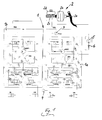
- the two attached hydraulic circuit diagrams (Fig. 1, Fig. 2) show two preferred exemplary embodiments of the present invention, reference number 1 in each case denoting a conventional hydraulic unit of a two-circuit vehicle brake system with ESP function.
- the block 1a of this hydraulic unit is assigned to the two wheel brake cylinders VL and VR of the vehicle front axle VA (and forms the first brake circuit), while the block 1b of the hydraulic unit 1 is assigned to the two wheel brake cylinders HL and HR of the rear axle HA and forms the second brake circuit
- the letter L denotes the left side of the vehicle and the letter R the right side of the vehicle.
- a return pump sRFP is provided as well as other known elements such as check valves, throttles and accumulators.
- Reference numeral 2 denotes the brake actuation unit for the driver of the vehicle, which is also customary, in its entirety, consisting of a brake pedal 2a, with which, with the interposition of a brake booster 2b, a two-circuit master brake cylinder 2c is actuated, which is fed from a brake fluid reservoir 2d ,
- a pressure sensor 3 is also provided in a connecting line from the master brake cylinder 2c to the first brake circuit of the front axle VA.
- a further pressure sensor 4 is provided in the brake fluid line leading to the wheel brake cylinder VL.
- block 1a of hydraulic unit 1 and thus the brake circuit of front axle VA is assigned an auxiliary pump 5, which can be driven by an electric motor (not shown) and downstream of which a check valve 6 opening in the pump delivery direction is provided.
- This auxiliary pump 5 is fed from the part of the master brake cylinder 2c assigned to the block 1a or directly from the reservoir 2d.
- the auxiliary pump 5 can promote a brake fluid flow under pressure to the inlet valves EVVL and EVVR of the wheel brake cylinders VL and VR during operation.
- Control unit which the normally open intake valves EV, the normally closed exhaust valves AV and the return pump sRFP in the If necessary, i.e. to achieve an anti-lock function and Appropriately controls vehicle stabilization in a known manner.
- This or another electronic control unit can now also use the already mentioned the auxiliary pump 5 driving electric motor in a suitable manner control if the vehicle is braked by a driver assistance system is required. This, as well as the criteria that the Auxiliary pump 5 and the associated electric motor should meet before the description of the figures already explained in detail.
- a volume accumulator 7 is provided, which is preceded by a switching valve 8 and which is connected via a so-called compensation line 9 to the so-called main cylinder circuit of the front axle VA, ie the so-called compensation line 9 branches off from the hydraulic line leading from the master brake cylinder 2c to the auxiliary pump 5.
- the function of this volume accumulator 7 with the switching valve 8 was also explained in detail before the description of the figures, with the two pressure sensors for the query explained there whether the brake fluid pressure upstream and downstream of the intake valves EV of the wheel brake cylinders VL, VR is essentially the same 3 and 4 can be accessed.
- a large number of details can deviate from the exemplary embodiments shown without departing from the content of the claims.
Landscapes
- Physics & Mathematics (AREA)
- Fluid Mechanics (AREA)
- Engineering & Computer Science (AREA)
- Transportation (AREA)
- Mechanical Engineering (AREA)
- Regulating Braking Force (AREA)
Applications Claiming Priority (2)
| Application Number | Priority Date | Filing Date | Title |
|---|---|---|---|
| DE10324242 | 2003-05-28 | ||
| DE2003124242 DE10324242A1 (de) | 2003-05-28 | 2003-05-28 | Hydraulische Zweikreis-Fahrzeugbremsanlage |
Publications (2)
| Publication Number | Publication Date |
|---|---|
| EP1481863A1 true EP1481863A1 (fr) | 2004-12-01 |
| EP1481863B1 EP1481863B1 (fr) | 2011-10-19 |
Family
ID=33103623
Family Applications (1)
| Application Number | Title | Priority Date | Filing Date |
|---|---|---|---|
| EP04101651A Expired - Lifetime EP1481863B1 (fr) | 2003-05-28 | 2004-04-21 | Système hydraulique de freinage à deux circuits pour véhicules |
Country Status (2)
| Country | Link |
|---|---|
| EP (1) | EP1481863B1 (fr) |
| DE (1) | DE10324242A1 (fr) |
Cited By (3)
| Publication number | Priority date | Publication date | Assignee | Title |
|---|---|---|---|---|
| WO2012143313A1 (fr) * | 2011-04-19 | 2012-10-26 | Continental Teves Ag & Co. Ohg | Système de freinage pour véhicules automobiles et procédé permettant de faire fonctionner un système de freinage |
| US9205821B2 (en) | 2011-04-19 | 2015-12-08 | Continental Teves Ag & Co. Ohg | Brake system for motor vehicles |
| US9637102B2 (en) | 2011-04-28 | 2017-05-02 | Continental Teves Ag & Co. Ohg | Brake system for motor vehicles and method for operating the brake system |
Families Citing this family (1)
| Publication number | Priority date | Publication date | Assignee | Title |
|---|---|---|---|---|
| DE102016201111A1 (de) | 2016-01-26 | 2017-07-27 | Bayerische Motoren Werke Aktiengesellschaft | Verfahren zur Druckmodulation in einem Bremssystem eines Kraftfahrzeugs |
Citations (3)
| Publication number | Priority date | Publication date | Assignee | Title |
|---|---|---|---|---|
| DE4309470A1 (de) * | 1993-03-24 | 1994-09-29 | Bosch Gmbh Robert | Hydraulische Fahrzeugbremsanlage mit Blockierschutzeinrichtung |
| DE19541381A1 (de) * | 1995-11-07 | 1997-05-15 | Teves Gmbh Alfred | Bremsanlage mit einer Einrichtung zur Aktivbremsung |
| WO1998013241A1 (fr) * | 1996-09-26 | 1998-04-02 | Robert Bosch Gmbh | Systeme de freinage hydraulique pour vehicule |
Family Cites Families (7)
| Publication number | Priority date | Publication date | Assignee | Title |
|---|---|---|---|---|
| DE4213740A1 (de) * | 1992-04-25 | 1993-10-28 | Bosch Gmbh Robert | Verfahren zum Beschleunigen des Bremseneingriffs im Antriebsschlupfregelbetrieb und hydraulische Bremsanlage zur Durchführung des Verfahrens |
| DE4232311C1 (de) * | 1992-09-26 | 1994-02-24 | Bosch Gmbh Robert | Hydraulische Fahrzeugbremsanlage mit Blockierschutzeinrichtung |
| DE4312404A1 (de) * | 1993-04-16 | 1994-10-20 | Teves Gmbh Alfred | Fremdkraftbremssystem für Kraftfahrzeuge |
| DE4440517B4 (de) * | 1994-11-12 | 2004-04-15 | Robert Bosch Gmbh | Verfahren und Vorrichtung zur Ansteuerung einer Rückförderpumpe |
| DE19619985A1 (de) * | 1995-11-25 | 1997-05-28 | Bosch Gmbh Robert | Hydraulische Fahrzeugbremsanlage |
| DE19949816A1 (de) * | 1999-10-15 | 2001-04-19 | Bosch Gmbh Robert | Betätigungseinheit für eine Radbremse eines Kraftfahrzeugs |
| JP3939936B2 (ja) * | 2001-05-30 | 2007-07-04 | トヨタ自動車株式会社 | 車輌用制動制御装置 |
-
2003
- 2003-05-28 DE DE2003124242 patent/DE10324242A1/de not_active Ceased
-
2004
- 2004-04-21 EP EP04101651A patent/EP1481863B1/fr not_active Expired - Lifetime
Patent Citations (3)
| Publication number | Priority date | Publication date | Assignee | Title |
|---|---|---|---|---|
| DE4309470A1 (de) * | 1993-03-24 | 1994-09-29 | Bosch Gmbh Robert | Hydraulische Fahrzeugbremsanlage mit Blockierschutzeinrichtung |
| DE19541381A1 (de) * | 1995-11-07 | 1997-05-15 | Teves Gmbh Alfred | Bremsanlage mit einer Einrichtung zur Aktivbremsung |
| WO1998013241A1 (fr) * | 1996-09-26 | 1998-04-02 | Robert Bosch Gmbh | Systeme de freinage hydraulique pour vehicule |
Cited By (4)
| Publication number | Priority date | Publication date | Assignee | Title |
|---|---|---|---|---|
| WO2012143313A1 (fr) * | 2011-04-19 | 2012-10-26 | Continental Teves Ag & Co. Ohg | Système de freinage pour véhicules automobiles et procédé permettant de faire fonctionner un système de freinage |
| US9145119B2 (en) | 2011-04-19 | 2015-09-29 | Continental Teves Ag & Co. Ohg | Brake system for motor vehicles and method for operating a brake system |
| US9205821B2 (en) | 2011-04-19 | 2015-12-08 | Continental Teves Ag & Co. Ohg | Brake system for motor vehicles |
| US9637102B2 (en) | 2011-04-28 | 2017-05-02 | Continental Teves Ag & Co. Ohg | Brake system for motor vehicles and method for operating the brake system |
Also Published As
| Publication number | Publication date |
|---|---|
| DE10324242A1 (de) | 2004-12-16 |
| EP1481863B1 (fr) | 2011-10-19 |
Similar Documents
| Publication | Publication Date | Title |
|---|---|---|
| DE102018002990B4 (de) | Hydraulische Kraftfahrzeug-Bremsanlage und Verfahren zum Betreiben derselben | |
| EP2822822B1 (fr) | Procédé de détermination d'une courbe caractéristique pression-volume d'un frein sur roue | |
| DE4338066C1 (de) | Verfahren zur Durchführung eines automatischen Bremsvorgangs für Kraftfahrzeuge mit einem Antiblockiersystem | |
| EP0807039B1 (fr) | Procede pour faire fonctionner un systeme de freinage de vehicules a moteur a antiderapeur automatique | |
| WO2019197561A1 (fr) | Système de freinage hydraulique de véhicule et procédé pour le faire fonctionner | |
| DE102018003001A1 (de) | Hydraulische Kraftfahrzeug-Bremsanlage und Verfahren zum Betreiben derselben | |
| EP2616293A1 (fr) | Système de freinage hydraulique et procédé de fonctionnement | |
| DE102010002280A1 (de) | Bremssystem für ein Fahrzeug und Verfahren zum Betreiben eines Bremssystems eines Fahrzeugs | |
| DE19502925A1 (de) | Verfahren zum Betrieb eines elektronisch regelbaren Bremsbetätigungssystems | |
| EP2288525A1 (fr) | Dispositif de freinage pour véhicule à moteur | |
| DE4102496A1 (de) | Bremsdruck-steuereinrichtung | |
| EP1888386B1 (fr) | Compensation d'une baisse d'efficacite de freinage d'un systeme de freinage hydraulique pour vehicule terrestre | |
| EP1481864B1 (fr) | Méthode et dispositif pour freiner un véhicule automobile par un système d'assistance pour conducteur | |
| EP0775618A1 (fr) | Système de freinage hydraulique pour véhicules avec dispositif de contrÔle de patinage | |
| DE3705311A1 (de) | Hydraulische bremsanlage fuer kraftfahrzeuge | |
| DE10319194B3 (de) | Kombinierte hydraulische und elektromechanische Fahrzeugbremsanlage mit einer Bremskraftregeleinrichtung | |
| EP0867325B1 (fr) | Système de contrôle de freinage avec dispositif de commande de la vitesse pouvant être mis en circuit ou hors circuit | |
| EP1481863B1 (fr) | Système hydraulique de freinage à deux circuits pour véhicules | |
| EP1917168B1 (fr) | Procede et systeme de freinage pour moduler des pressions de freinage sur des motos | |
| DE102005061543B4 (de) | Hydraulische Zweikreis-Fahrzeugbremsanlage | |
| DE10137016B4 (de) | Verfahren zur Bremsdruckreglung | |
| DE3833542A1 (de) | Hydraulische kraftfahrzeug-bremsanlage mit antiblockierregeleinrichtung | |
| DE102007042816A1 (de) | Hydraulische Bremsanlage mit Bremsschlupfregelung | |
| EP3938254A2 (fr) | Procédé et appareil de commande pour éviter des broutements lors du ralentissement d'un véhicule | |
| DE3727664A1 (de) | Kraftfahrzeugbremsanlage mit schlupfregelung |
Legal Events
| Date | Code | Title | Description |
|---|---|---|---|
| PUAI | Public reference made under article 153(3) epc to a published international application that has entered the european phase |
Free format text: ORIGINAL CODE: 0009012 |
|
| AK | Designated contracting states |
Kind code of ref document: A1 Designated state(s): AT BE BG CH CY CZ DE DK EE ES FI FR GB GR HU IE IT LI LU MC NL PL PT RO SE SI SK TR |
|
| AX | Request for extension of the european patent |
Extension state: AL LT LV MK |
|
| 17P | Request for examination filed |
Effective date: 20041103 |
|
| AKX | Designation fees paid |
Designated state(s): DE FR GB IT |
|
| 17Q | First examination report despatched |
Effective date: 20071012 |
|
| GRAP | Despatch of communication of intention to grant a patent |
Free format text: ORIGINAL CODE: EPIDOSNIGR1 |
|
| RIN1 | Information on inventor provided before grant (corrected) |
Inventor name: UNTERFORSTHUBER, JAKOB |
|
| GRAS | Grant fee paid |
Free format text: ORIGINAL CODE: EPIDOSNIGR3 |
|
| GRAA | (expected) grant |
Free format text: ORIGINAL CODE: 0009210 |
|
| AK | Designated contracting states |
Kind code of ref document: B1 Designated state(s): DE FR GB IT |
|
| REG | Reference to a national code |
Ref country code: GB Ref legal event code: FG4D Free format text: NOT ENGLISH |
|
| REG | Reference to a national code |
Ref country code: DE Ref legal event code: R096 Ref document number: 502004012994 Country of ref document: DE Effective date: 20111222 |
|
| PLBE | No opposition filed within time limit |
Free format text: ORIGINAL CODE: 0009261 |
|
| STAA | Information on the status of an ep patent application or granted ep patent |
Free format text: STATUS: NO OPPOSITION FILED WITHIN TIME LIMIT |
|
| 26N | No opposition filed |
Effective date: 20120720 |
|
| REG | Reference to a national code |
Ref country code: DE Ref legal event code: R097 Ref document number: 502004012994 Country of ref document: DE Effective date: 20120720 |
|
| REG | Reference to a national code |
Ref country code: FR Ref legal event code: PLFP Year of fee payment: 13 |
|
| PGFP | Annual fee paid to national office [announced via postgrant information from national office to epo] |
Ref country code: DE Payment date: 20160427 Year of fee payment: 13 |
|
| REG | Reference to a national code |
Ref country code: FR Ref legal event code: PLFP Year of fee payment: 14 |
|
| PGFP | Annual fee paid to national office [announced via postgrant information from national office to epo] |
Ref country code: FR Payment date: 20170424 Year of fee payment: 14 Ref country code: GB Payment date: 20170425 Year of fee payment: 14 |
|
| PGFP | Annual fee paid to national office [announced via postgrant information from national office to epo] |
Ref country code: IT Payment date: 20170420 Year of fee payment: 14 |
|
| REG | Reference to a national code |
Ref country code: DE Ref legal event code: R119 Ref document number: 502004012994 Country of ref document: DE |
|
| PG25 | Lapsed in a contracting state [announced via postgrant information from national office to epo] |
Ref country code: DE Free format text: LAPSE BECAUSE OF NON-PAYMENT OF DUE FEES Effective date: 20171103 |
|
| GBPC | Gb: european patent ceased through non-payment of renewal fee |
Effective date: 20180421 |
|
| PG25 | Lapsed in a contracting state [announced via postgrant information from national office to epo] |
Ref country code: GB Free format text: LAPSE BECAUSE OF NON-PAYMENT OF DUE FEES Effective date: 20180421 |
|
| PG25 | Lapsed in a contracting state [announced via postgrant information from national office to epo] |
Ref country code: IT Free format text: LAPSE BECAUSE OF NON-PAYMENT OF DUE FEES Effective date: 20180421 Ref country code: FR Free format text: LAPSE BECAUSE OF NON-PAYMENT OF DUE FEES Effective date: 20180430 |