EP1482093A2 - Dispositif de contrôle pour brosses rotatives dans une balayeuse - Google Patents
Dispositif de contrôle pour brosses rotatives dans une balayeuse Download PDFInfo
- Publication number
- EP1482093A2 EP1482093A2 EP20040011731 EP04011731A EP1482093A2 EP 1482093 A2 EP1482093 A2 EP 1482093A2 EP 20040011731 EP20040011731 EP 20040011731 EP 04011731 A EP04011731 A EP 04011731A EP 1482093 A2 EP1482093 A2 EP 1482093A2
- Authority
- EP
- European Patent Office
- Prior art keywords
- fluid
- swept
- rotating brush
- force
- dynamic
- Prior art date
- Legal status (The legal status is an assumption and is not a legal conclusion. Google has not performed a legal analysis and makes no representation as to the accuracy of the status listed.)
- Withdrawn
Links
Images


Classifications
-
- A—HUMAN NECESSITIES
- A47—FURNITURE; DOMESTIC ARTICLES OR APPLIANCES; COFFEE MILLS; SPICE MILLS; SUCTION CLEANERS IN GENERAL
- A47L—DOMESTIC WASHING OR CLEANING; SUCTION CLEANERS IN GENERAL
- A47L11/00—Machines for cleaning floors, carpets, furniture, walls, or wall coverings
- A47L11/40—Parts or details of machines not provided for in groups A47L11/02 - A47L11/38, or not restricted to one of these groups, e.g. handles, arrangements of switches, skirts, buffers, levers
- A47L11/4011—Regulation of the cleaning machine by electric means; Control systems and remote control systems therefor
-
- A—HUMAN NECESSITIES
- A47—FURNITURE; DOMESTIC ARTICLES OR APPLIANCES; COFFEE MILLS; SPICE MILLS; SUCTION CLEANERS IN GENERAL
- A47L—DOMESTIC WASHING OR CLEANING; SUCTION CLEANERS IN GENERAL
- A47L11/00—Machines for cleaning floors, carpets, furniture, walls, or wall coverings
- A47L11/24—Floor-sweeping machines, motor-driven
-
- A—HUMAN NECESSITIES
- A47—FURNITURE; DOMESTIC ARTICLES OR APPLIANCES; COFFEE MILLS; SPICE MILLS; SUCTION CLEANERS IN GENERAL
- A47L—DOMESTIC WASHING OR CLEANING; SUCTION CLEANERS IN GENERAL
- A47L11/00—Machines for cleaning floors, carpets, furniture, walls, or wall coverings
- A47L11/40—Parts or details of machines not provided for in groups A47L11/02 - A47L11/38, or not restricted to one of these groups, e.g. handles, arrangements of switches, skirts, buffers, levers
- A47L11/4052—Movement of the tools or the like perpendicular to the cleaning surface
- A47L11/4058—Movement of the tools or the like perpendicular to the cleaning surface for adjusting the height of the tool
-
- E—FIXED CONSTRUCTIONS
- E01—CONSTRUCTION OF ROADS, RAILWAYS, OR BRIDGES
- E01H—STREET CLEANING; CLEANING OF PERMANENT WAYS; CLEANING BEACHES; DISPERSING OR PREVENTING FOG IN GENERAL CLEANING STREET OR RAILWAY FURNITURE OR TUNNEL WALLS
- E01H1/00—Removing undesirable matter from roads or like surfaces, with or without moistening of the surface
- E01H1/02—Brushing apparatus, e.g. with auxiliary instruments for mechanically loosening dirt
- E01H1/05—Brushing apparatus, e.g. with auxiliary instruments for mechanically loosening dirt with driven brushes
- E01H1/056—Brushing apparatus, e.g. with auxiliary instruments for mechanically loosening dirt with driven brushes having horizontal axes
-
- E—FIXED CONSTRUCTIONS
- E01—CONSTRUCTION OF ROADS, RAILWAYS, OR BRIDGES
- E01H—STREET CLEANING; CLEANING OF PERMANENT WAYS; CLEANING BEACHES; DISPERSING OR PREVENTING FOG IN GENERAL CLEANING STREET OR RAILWAY FURNITURE OR TUNNEL WALLS
- E01H1/00—Removing undesirable matter from roads or like surfaces, with or without moistening of the surface
- E01H1/08—Pneumatically dislodging or taking-up undesirable matter or small objects; Drying by heat only or by streams of gas; Cleaning by projecting abrasive particles
- E01H1/0827—Dislodging by suction; Mechanical dislodging-cleaning apparatus with independent or dependent exhaust, e.g. dislodging-sweeping machines with independent suction nozzles ; Mechanical loosening devices working under vacuum
- E01H1/0854—Apparatus in which the mechanically dislodged dirt is partially sucked up, e.g. dislodging-sweeping apparatus with dirt collector in brush housing or dirt container
Definitions
- the invention relates to a rotating brush controlling apparatus in a floor sweeping machine, of a type detailed in the first claim.
- the sweeping machines may be of a small and a medium size and be suitable for the cleaning of warehouses, commercial centres, sheds, industrial centres and the like.
- the small to medium size machines are also suitable for occasional uses, for instance for a short period after the closing of a commercial centre, and are on various occasions used by operators that are only occasionally taking control of them.
- the brushes must both be arrested and lifted, because if they are arrested but left in a lowered position while the machine moves on for relocating, considerable and irregular bristle wear occurs on the brushes.
- a widely encountered usage problem is also related to fact that the floors of warehouses, commercial centres and the like may exhibit small steps, contours or differences in height, for instance between different departments, or because of the passing of cables or other.
- the hollowed areas and small recesses are also swept out to a limited degree, if the brushes are partially kept raised by higher areas.
- the brushes are tied up so as to prevent them from oscillating freely, but in this case the steps and contours on the surface to be swept are leading to shocks and difficulties in operating the machines.
- the technical aim of this invention is to conceive a rotating brush controlling apparatus in a floor sweeping machine, capable of overcoming the mentioned drawbacks, and in particular of achieving optimum cleaning results even in areas difficult to handle and in the presence of substances not easily removed, without demanding special skills from the personnel in charge.
- the apparatus according to the invention is inserted in a sweeping machine indicated as a whole by the number 1.
- the wheels 2a, 2b sustain a frame 3 supporting collecting organs 4 for dust and refuse, and moving devices 5 for the vehicle 1.
- the collecting organs 4 comprise a container 6 for accumulating dust and refuse.
- the container 6 is substantially placed between the front wheels 2a and fitted with an opening and closing door 6a which is also suitable for fulfilling the function of a slide for inserting the dust and refuse in the container 6.
- the collecting organs 4 further comprise one or more rotating brushes suitable for operating on a surface to be swept 7 .
- rotating brushes suitable for operating on a surface to be swept 7 .
- several rotating brushes are present: a central brush 8 and at least one and preferably two auxiliary brushes 9 .
- the central brush 8 is a substantially cylindrical roller brush having a rotating axle 8a substantially parallel to the surface to be swept 7.
- the brush extends in practice over the entire length of the machine 1.
- the auxiliary brushes 9 are instead profiled as a cup or as a truncated cone and exhibit a rotating axis across the surface 7.
- the auxiliary brushes 9 can be positioned in front of the machine 1, on the right side and on the left side of the same, so as to convey the dust and refuse from the sides toward the central area of the machine, which holds the central brush 8.
- Fig.1 shows the auxiliary left front brush 9 only.
- the collecting organs 4 further comprise an aspirating fan, not shown here, which is placed upstream of the container 6 and suitable for aspirating the air from the container 6 itself, through an interposed filter, both to prevent the dust of the container from escaping into the surrounding environment, and to achieve an effective aspirating function reaching down to the level of the surface to be swept 7.
- an aspirating fan not shown here, which is placed upstream of the container 6 and suitable for aspirating the air from the container 6 itself, through an interposed filter, both to prevent the dust of the container from escaping into the surrounding environment, and to achieve an effective aspirating function reaching down to the level of the surface to be swept 7.
- the frame 3 supports at least part of the rotating brushes in an oscillating manner, so as to allow the rotating brushes themselves to rise and fall with respect to the surface to be swept 7.
- the moving devices 5 comprise steering instruments in themselves known, of whose the steering wheel 5a and its relative control station 5b are shown in Fig.1, and a traction device, in itself known, which is equipped with a motor, for example an internal combustion or an electrical one.
- the machine 1 In order to control the collecting organs 4, and in particular the rotating brushes, the machine 1 exhibits a controlling apparatus 12 , which forms the specific object of this invention.
- the controlling apparatus 12 includes mainly a lifting device 15 capable of applying a lifting force 15a suitable for lifting at least one rotating brush, in particular at least the central brush 8, so as to remove the same from the surface to be swept 7.
- the lifting device 15 is preferably carried out with elastically deformable organs, such as at least a spring.
- the lifting device 15 is neutralized by at least one actuating device 16 suitable for applying a working force 16a opposing the lifting force 15a.
- at least the central brush 8 and at least one actuating device 16 are cinematically linked to each other - meaning that a motion of one of them also entails a simultaneous motion of the other - and that the working force 16a be selectively greater than the lifting force 15a, in order to neutralize the lifting device 15 and to simultaneously force the central brush 8, in a selected manner, on the surface to be swept 7.
- the adjusting devices 24 suitable for optionally selecting the working force 16a, are in fact provided.
- the adjusting devices 24 comprise at least one adjusting unit 25 suitable for adjusting the working force 16a and a control-wheel 29 acting on the adjusting unit 25 and placed matching the sweeping machine controls.
- the apparatus 12 comprises a fluid-dynamic system 13 suitable for circulating a pressurized fluid (for instance air, water or oil), which is the pressurized fluid activating the fluid-dynamic motors, in particular a first fluid-dynamic motor 14a ( Figures 2, 3 and 4), a second fluid-dynamic motor 14b ( Figures 1 and 4) and an eventual further fluid-dynamic motor 14c ( Figure 4), selectively suitable for controlling the rotation of the rotating brushes, one for each of the rotating brushes in question.
- a pressurized fluid for instance air, water or oil
- the first motor 14a is acting on the central brush 8, while the second and the third fluid-dynamic motors 14a and 14c act on the two lateral brushes 9. It is however noted that the third fluid-dynamic motor 14c, which is provided for the second lateral brush 9, is shown as a dashed line in Figure 4, because the second lateral brush may be omitted, as already explained.
- actuating devices 16 as there are rotating brushes, and said devices are fluid-dynamic cylinders selectively indicated by 16', 16", 16"' in Figure 4, and supplied by the fluid-dynamic system 13.
- An adjusting unit 25 interposed between the cylinder 16 itself and the fluid-dynamic system 13 is provided opposite each actuating device or fluid-dynamic cylinder 16.
- the fluid-dynamic system 13 is preferably of a hydraulic oil type and as illustrated in Figure 4.
- This system provides for at least one pump 17 which on one side connects to a hydraulic oil collecting tank 18 , and on the opposite side connects to a group of elements or block 19 comprising, among other things, various circuit branches, various electrical distributors and various valves.
- the block 19 in turn supplies the three fluid-dynamic motors 14a, 14b, 14c and the three fluid-dynamic cylinders 16', 16", 16"', respectively.
- a maximum pressure valve 22 is arranged between the channels 20 and 21, which directly discharges the hydraulic oil supplied by the pump 17, whenever necessary.
- the discharge channel 20 Downstream of the top pressure valve 22, the discharge channel 20 splits up into various branches: a first branch 20a, supplying the first fluid-dynamic cylinder 16', a second branch 20b supplying the first fluid-dynamic motor 14a, a third branch 20c supplying the first and the second fluid-dynamic cylinders 16" and 16'" in series, and a fourth branch 20d supplying the second and third fluid-dynamic motors 14b and 14c in series.
- the number 23 indicates the electrical distributors that are - on command - controlling the flow of the hydraulic oil opposite said branches.
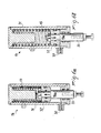
- the adjusting devices 24 comprise adjusting units 25, as illustrated in detail and in cross section in Figure 5a, and at least one adjusting control 29, as shown in Figure 5b.
- Each adjusting unit 25 is suitable for establishing - in the respective fluid-dynamic cylinder 16 - a selected working pressure.
- the mentioned working force 16a depends on said working pressure.
- a further characteristic of the adjusting unit 25 is that of keeping the selected working pressure substantially constant for the respective fluid-dynamic cylinder 16 in the presence of any irregularities of said surface to be swept 7.
- the adjusting unit 25 is in practice an adjusting valve of a type known as a "Pressure Reducing and Relieving Valve", or in short as a “Relieving Valve”, which is placed at least opposite the branch 20a of the circuit 13.
- Said valve has a cylindrical profile, a mouth 25c and a small internally mobile piston 26 for the oil pressure; the oil pressure shifts the small piston 26, that in sliding allows a selective passing of the oil across appropriate openings 25a, 25b.
- a screwable knob 27 adjusts the mobility of the small piston and its resistance to motion and an adjusting spring 28 interposed between the knob 27 and the small piston 26.
- a greater or lesser screwing action of the knob 27 determines in practice, through a greater or lesser compression of the adjusting spring 28, the working pressure at which the oil is allowed to pass to the respective fluid-dynamic cylinders 16.
- the adjusting unit or valve 25 be suitable for selecting, when operating the knob 27, some working pressure values ranging between five and forty bar.
- the working pressure is substantially kept constant. Should the pressure in fact exceed the predetermined level, the small piston 26 is forced to slide further, thus compressing the adjusting spring 28 and opening up passages that determine a partial discharge of the oil and the substantial reestablishment of the working pressure set up by the knob 27.
- the adjusting control 29, through which any operator running the sweeping machine 1 acts on at least one unit or adjusting valve 25, is realized by a hand-wheel associated with a graduated scale 29a or with indicators of a functional type, depending on the various cleaning requirements.
- the hand-wheel acts through appropriate fittings on the knob 27, but the same knob 27 can also be made accessible from the steering station.
- a single adjusting control 29 is preferably arranged for all the units or adjusting valves 25, but it is also possible to arrange as many adjusting controls 29 as there are units 25.
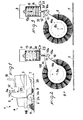
- Figures 2 and 3 show, in reference to the central roller brush 8, that the rotating brushes are preferably controlled by a lever 10, such as a first-type level rotating around a fulcrum 11, as outlined before.
- the fulcrum 11 is arranged so as to present an axis substantially parallel to the surface to be swept 7.
- the lever 10 is then provided so as to amplify the controlling action received, and for this purpose the Figures 2 and 3 show a lever equipped with a resistance arm - extending between the axis of rotation 8a of the brush and the fulcrum 11 - has a length exceeding that of the power arm which extends between the fulcrum 11 and the fluid-dynamic cylinder 16.
- each actuating device or fluid-dynamic cylinder 16 is connected to the fluid-dynamic system 13 by a channel 30, and is of a single-acting type.
- each fluid-dynamic cylinder 16 comprises a cylindrical body 31 sustained by a frame 3, a mobile piston 32 inside the cylindrical body 31, and a stem 33 firmly attached to the piston 32 and at least partially protruding from the cylindrical body 31.
- the fluid-dynamic cylinder is linked to a rotating brush matching the stem 33, through an interposed lever 10.
- each motion of the stem 33 - in whatever direction - necessarily matches a motion of the respective brush.
- lifting devices 15 are provided as there are fluid-dynamic cylinders 16, and these lifting devices 15 preferably consist of compression springs coaxially arranged with the respective fluid-dynamic cylinders 16.
- Each compression spring is preferably housed inside a cylindrical body 31 and acting on a piston 32 in opposition to the action of the pressurized fluid. In the absence of a working pressure, each compression spring shifts the respective piston 32 and the respective stem 33 to a position of maximum extension, so as to determine a lifting of the respective rotating brush, through the lever 10, as in the case shown in Figure 2.
- the compression spring must be particularly effective, as the rotating brushes can be heavy. In the case of Fig.2, the compression springs lifts a roller brush that can in itself, meaning without the weight of the associated fluid-dynamic motor 14a, have a weight of for instance about thirty kilograms.
- the operation of the apparatus 12 is as follows.
- the operator In order to start the work, the operator must place himself with the machine 1 on the surface of the floor to be swept or cleaned up, for instance in a shed or in a warehouse.
- the operator activates the collecting organs 4.
- he activates the oil circulation in the fluid-dynamic system 13, thus determining both the operation of the fluid-dynamic motors and the activation of the actuating devices or fluid-dynamic cylinders 16, and their consequent downward shifting of the rotating brushes.
- the rotating brushes are linked to the stem 33 and therefore forced to lower themselves and partially impinge on the surface to be swept 7 while turning.
- This pressure may be adjusted in a very simple manner by the operator himself, for instance by using the adjusting control or hand-wheei 29 set on the control panel, and by acting on the knob 27 of the unit or the adjusting valve 25.
- the rotation of a simple hand-wheel selectively increases or decreases the working pressure in at least the actuating device or fluid-dynamic cylinder 16 that controls the most important'and always available rotating brush: the roller brush 8.
- the hand-wheel's position may be suggested by simple indicators such as by the graduated scale 29a or by simple instructions set opposite the hand-wheel itself.
- One position may for example be indicated for dust and refuse composed of paper, plastics and packing residues; another position for instance by liquids and moist food elements, and a final position for removing pollutants, oily substances, colours, hydrocarbon residues etc. The latter potentially adhere to the floors to be cleaned and a very robust action of the rotating brushes is therefore in order, at the highest allowable pressure acting on the floor.
- the adjusting unit or valve 25 keeps the pre-set pressure at a constant level, the machine is therefore capable of operating correctly even in the presence of humps, steps, and differences in height.
- the steps and differences in height would in fact tend to compress the fluid-dynamic cylinders 16.
- These are however not reacting by suddenly increasing the working pressure, but by discharging the excess pressurized oil through the adjusting units or valves 25.
- At the end of operating it merely suffices to close the door 6a and to move the machine 1 toward a discharging point, after deactivating the collecting organs 4. For this latter operation it suffices to stop the oil circulating inside the fluid-dynamic system 13; this determines both an arrest and a lifting of the brushes.
- the invention allows important advantages.
- the cleaning thus always turns out to be effective and satisfactory, even in the presence of some personnel with scant experience.
- a further asset is related to the fact that the lifts occur without losing adherence, as the working pressure remains constant.
Landscapes
- Engineering & Computer Science (AREA)
- Architecture (AREA)
- Civil Engineering (AREA)
- Structural Engineering (AREA)
- Cleaning In General (AREA)
- Harvester Elements (AREA)
Applications Claiming Priority (2)
| Application Number | Priority Date | Filing Date | Title |
|---|---|---|---|
| ITMI20031080 | 2003-05-29 | ||
| IT001080A ITMI20031080A1 (it) | 2003-05-29 | 2003-05-29 | Apparato di controllo di una spazzola girevole, |
Publications (2)
| Publication Number | Publication Date |
|---|---|
| EP1482093A2 true EP1482093A2 (fr) | 2004-12-01 |
| EP1482093A3 EP1482093A3 (fr) | 2005-08-10 |
Family
ID=30131105
Family Applications (1)
| Application Number | Title | Priority Date | Filing Date |
|---|---|---|---|
| EP04011731A Withdrawn EP1482093A3 (fr) | 2003-05-29 | 2004-05-18 | Dispositif de contrôle pour brosses rotatives dans une balayeuse |
Country Status (5)
| Country | Link |
|---|---|
| US (1) | US7395572B2 (fr) |
| EP (1) | EP1482093A3 (fr) |
| JP (1) | JP4447959B2 (fr) |
| CN (1) | CN1275568C (fr) |
| IT (1) | ITMI20031080A1 (fr) |
Cited By (1)
| Publication number | Priority date | Publication date | Assignee | Title |
|---|---|---|---|---|
| CN107080498A (zh) * | 2017-05-15 | 2017-08-22 | 意诺科技有限公司 | 一种滚刷装置及其控制方法和清洁设备 |
Families Citing this family (15)
| Publication number | Priority date | Publication date | Assignee | Title |
|---|---|---|---|---|
| JP4703239B2 (ja) * | 2005-04-07 | 2011-06-15 | アマノ株式会社 | フイルタ目詰まり検出機能を備えた床面清掃機 |
| RU2326424C2 (ru) * | 2006-01-23 | 2008-06-10 | Новомосковский институт Российского химико-технологического университета им. Д.И. Менделеева | Система автоматического поддержания температурного профиля в реакторе |
| CN111281266B (zh) | 2011-04-29 | 2021-12-10 | 艾罗伯特公司 | 移动清洁机器人和自主覆盖机器人 |
| US11471020B2 (en) | 2011-04-29 | 2022-10-18 | Irobot Corporation | Robotic vacuum cleaning system |
| JP6090016B2 (ja) * | 2013-07-09 | 2017-03-08 | 三菱電機株式会社 | 自走式掃除機 |
| US11174607B2 (en) * | 2015-04-16 | 2021-11-16 | Nilfisk A/S | Apparatus for collecting garbage and debris for a motor-sweeper |
| CN106037592A (zh) * | 2015-10-27 | 2016-10-26 | 陈仰峰 | 扫地机 |
| US20190133400A1 (en) * | 2016-05-11 | 2019-05-09 | Aktiebolaget Electrolux | Adjusting height of a robotic cleaning device |
| CN105852743A (zh) * | 2016-05-24 | 2016-08-17 | 昆山邦泰汽车零部件制造有限公司 | 一种扫地机器人支撑结构 |
| TWI665107B (zh) | 2017-12-12 | 2019-07-11 | 財團法人工業技術研究院 | 行動載具、地面處理機具及其姿態調整方法 |
| WO2020124570A1 (fr) * | 2018-12-21 | 2020-06-25 | 深圳市赫兹科技有限公司 | Tête de nettoyage de nettoyeur à rouleau unique, tête de nettoyage de nettoyeur à deux rouleaux, ensemble de direction et dispositif de nettoyage de sol |
| US11109727B2 (en) | 2019-02-28 | 2021-09-07 | Irobot Corporation | Cleaning rollers for cleaning robots |
| CN111733745A (zh) * | 2020-07-03 | 2020-10-02 | 北京金恺环境科技有限公司 | 一种边置大梁扫盘进出系统 |
| CN112832167A (zh) * | 2021-01-11 | 2021-05-25 | 周金红 | 一种市政道路清洁装置 |
| CN114081401B (zh) * | 2021-11-19 | 2022-08-30 | 太和县人民医院 | 一种用于维持门诊秩序的无人导航车 |
Citations (2)
| Publication number | Priority date | Publication date | Assignee | Title |
|---|---|---|---|---|
| GB695207A (en) * | 1950-06-09 | 1953-08-05 | Smith S Jacking Systems Ltd | Improvements in or relating to means for controlling the pressure of the brush of a road sweeping machine against the road |
| EP0795647A1 (fr) | 1996-03-14 | 1997-09-17 | DULEVO INTERNATIONAL S.p.A. | Véhicule de ramassage de poussières et de déchets |
Family Cites Families (6)
| Publication number | Priority date | Publication date | Assignee | Title |
|---|---|---|---|---|
| DE1026771B (de) * | 1954-10-13 | 1958-03-27 | Streicher Fa M | Vorrichtung zum Heben und Senken eines an einem Fahrzeug angelenkten Arbeitsgeraetes |
| GB1172630A (en) * | 1967-05-26 | 1969-12-03 | Asbrink Eiker Ab | Improvements in or relating to Sweeping Machines. |
| US3790981A (en) * | 1972-09-15 | 1974-02-12 | B Young | Surface sweeping machine equipped with gutter brush |
| US4138756A (en) * | 1977-10-03 | 1979-02-13 | Tennant Company | Surface maintenance machine drive and brush |
| GB8421713D0 (en) * | 1984-08-28 | 1984-10-03 | Unilever Plc | Floor-cleaning machine |
| DE3626201A1 (de) * | 1986-08-01 | 1988-02-04 | Rexroth Mannesmann Gmbh | Hydraulische steuereinrichtung fuer eine von zwei zylindern gehaltene kehrwalze einer kehrmaschine |
-
2003
- 2003-05-29 IT IT001080A patent/ITMI20031080A1/it unknown
-
2004
- 2004-05-18 EP EP04011731A patent/EP1482093A3/fr not_active Withdrawn
- 2004-05-27 US US10/854,283 patent/US7395572B2/en not_active Expired - Fee Related
- 2004-05-28 JP JP2004159723A patent/JP4447959B2/ja not_active Expired - Fee Related
- 2004-05-28 CN CNB2004100472653A patent/CN1275568C/zh not_active Expired - Fee Related
Patent Citations (2)
| Publication number | Priority date | Publication date | Assignee | Title |
|---|---|---|---|---|
| GB695207A (en) * | 1950-06-09 | 1953-08-05 | Smith S Jacking Systems Ltd | Improvements in or relating to means for controlling the pressure of the brush of a road sweeping machine against the road |
| EP0795647A1 (fr) | 1996-03-14 | 1997-09-17 | DULEVO INTERNATIONAL S.p.A. | Véhicule de ramassage de poussières et de déchets |
Cited By (2)
| Publication number | Priority date | Publication date | Assignee | Title |
|---|---|---|---|---|
| CN107080498A (zh) * | 2017-05-15 | 2017-08-22 | 意诺科技有限公司 | 一种滚刷装置及其控制方法和清洁设备 |
| CN107080498B (zh) * | 2017-05-15 | 2019-03-26 | 意诺科技有限公司 | 一种滚刷装置及其控制方法和清洁设备 |
Also Published As
| Publication number | Publication date |
|---|---|
| JP4447959B2 (ja) | 2010-04-07 |
| US7395572B2 (en) | 2008-07-08 |
| ITMI20031080A0 (it) | 2003-05-29 |
| CN1275568C (zh) | 2006-09-20 |
| CN1572223A (zh) | 2005-02-02 |
| US20040237231A1 (en) | 2004-12-02 |
| EP1482093A3 (fr) | 2005-08-10 |
| ITMI20031080A1 (it) | 2004-11-30 |
| JP2004351216A (ja) | 2004-12-16 |
Similar Documents
| Publication | Publication Date | Title |
|---|---|---|
| US7395572B2 (en) | Rotating brush controlling apparatus in a floor sweeping machine | |
| US4219155A (en) | High pressure water cleaning device for floors, gratings, and paint laden handling devices | |
| DE60111306T2 (de) | Bürstenkopfpositioniervorrichtung | |
| US3833961A (en) | Surface maintenance machine | |
| EP0739828B1 (fr) | Dispositif pour lever et basculer une poubelle | |
| US4685228A (en) | Snow-removing machine | |
| US20050060834A1 (en) | Debris collection systems, vehicles, and methods | |
| US4443271A (en) | Method for cleaning floor grates in place with high pressure water jets | |
| EP0247017A2 (fr) | Dispositif de nettoyage pour une machine à courroie abrasive large | |
| KR20150109812A (ko) | 노면의 상태에 따라 청소강도를 조절하는 청소차 | |
| US2829391A (en) | Power driven cleaning machine having fluid control system | |
| ITMI960185U1 (it) | Veicolo per la raccolta di polvere e rifiuti | |
| US2748720A (en) | Track cleaner | |
| US3414200A (en) | Vehicles for spreading discrete materials | |
| US5341828A (en) | Truck tire washing | |
| WO2007063452A2 (fr) | Systeme de nettoyage par recyclage | |
| HK1070675A (en) | Rotating brush controlling apparatus in a floor sweeping machine | |
| DE2821627A1 (de) | Hoehenfuehrung der buerstenwalze und/oder tellerbuerste einer strassenreinigungsmaschine | |
| US5481776A (en) | Brush pressure system | |
| EP1046748A1 (fr) | Rouleau compresseur | |
| US11660604B2 (en) | Milling machine | |
| EP1072727B1 (fr) | Véhicule et procédé pour nettoyer les surfaces | |
| DE2239385C3 (de) | Vorrichtung zum Reinigen von Filterbecken bei der Trinkwasserbereitung | |
| DE60307883T2 (de) | Gerät zum aufkratzen von rohrinnenflächen | |
| KR102136795B1 (ko) | 세척수 재활용 노면청소 살수차용 물회수유닛 |
Legal Events
| Date | Code | Title | Description |
|---|---|---|---|
| PUAI | Public reference made under article 153(3) epc to a published international application that has entered the european phase |
Free format text: ORIGINAL CODE: 0009012 |
|
| AK | Designated contracting states |
Kind code of ref document: A2 Designated state(s): AT BE BG CH CY CZ DE DK EE ES FI FR GB GR HU IE IT LI LU MC NL PL PT RO SE SI SK TR |
|
| AX | Request for extension of the european patent |
Extension state: AL HR LT LV MK |
|
| PUAL | Search report despatched |
Free format text: ORIGINAL CODE: 0009013 |
|
| REG | Reference to a national code |
Ref country code: HK Ref legal event code: DE Ref document number: 1070675 Country of ref document: HK |
|
| AK | Designated contracting states |
Kind code of ref document: A3 Designated state(s): AT BE BG CH CY CZ DE DK EE ES FI FR GB GR HU IE IT LI LU MC NL PL PT RO SE SI SK TR |
|
| AX | Request for extension of the european patent |
Extension state: AL HR LT LV MK |
|
| AKX | Designation fees paid | ||
| REG | Reference to a national code |
Ref country code: DE Ref legal event code: 8566 |
|
| 17P | Request for examination filed |
Effective date: 20060419 |
|
| R17P | Request for examination filed (corrected) |
Effective date: 20060413 |
|
| RAX | Requested extension states of the european patent have changed |
Extension state: MK Payment date: 20060213 Extension state: HR Payment date: 20060213 Extension state: AL Payment date: 20060213 |
|
| RBV | Designated contracting states (corrected) |
Designated state(s): AT BE BG CH CY CZ DE DK EE ES FI FR GB GR HU IE IT LI LU MC NL PL PT RO SE SI SK TR |
|
| RAX | Requested extension states of the european patent have changed |
Extension state: MK Payment date: 20060213 Extension state: LV Payment date: 20060213 Extension state: LT Payment date: 20060213 Extension state: HR Payment date: 20060213 Extension state: AL Payment date: 20060213 |
|
| REG | Reference to a national code |
Ref country code: HK Ref legal event code: WD Ref document number: 1070675 Country of ref document: HK |
|
| STAA | Information on the status of an ep patent application or granted ep patent |
Free format text: STATUS: THE APPLICATION IS DEEMED TO BE WITHDRAWN |
|
| 18D | Application deemed to be withdrawn |
Effective date: 20111201 |