EP1482154A2 - Circuit et méthode pour commander au moins un composant électrique d'un véhicule - Google Patents
Circuit et méthode pour commander au moins un composant électrique d'un véhicule Download PDFInfo
- Publication number
- EP1482154A2 EP1482154A2 EP20040102214 EP04102214A EP1482154A2 EP 1482154 A2 EP1482154 A2 EP 1482154A2 EP 20040102214 EP20040102214 EP 20040102214 EP 04102214 A EP04102214 A EP 04102214A EP 1482154 A2 EP1482154 A2 EP 1482154A2
- Authority
- EP
- European Patent Office
- Prior art keywords
- control unit
- circuit arrangement
- digital control
- control signal
- motor vehicle
- Prior art date
- Legal status (The legal status is an assumption and is not a legal conclusion. Google has not performed a legal analysis and makes no representation as to the accuracy of the status listed.)
- Withdrawn
Links
Images


Classifications
-
- B—PERFORMING OPERATIONS; TRANSPORTING
- B60—VEHICLES IN GENERAL
- B60R—VEHICLES, VEHICLE FITTINGS, OR VEHICLE PARTS, NOT OTHERWISE PROVIDED FOR
- B60R16/00—Electric or fluid circuits specially adapted for vehicles and not otherwise provided for; Arrangement of elements of electric or fluid circuits specially adapted for vehicles and not otherwise provided for
- B60R16/02—Electric or fluid circuits specially adapted for vehicles and not otherwise provided for; Arrangement of elements of electric or fluid circuits specially adapted for vehicles and not otherwise provided for electric constitutive elements
- B60R16/023—Electric or fluid circuits specially adapted for vehicles and not otherwise provided for; Arrangement of elements of electric or fluid circuits specially adapted for vehicles and not otherwise provided for electric constitutive elements for transmission of signals between vehicle parts or subsystems
- B60R16/0231—Circuits relating to the driving or the functioning of the vehicle
-
- B—PERFORMING OPERATIONS; TRANSPORTING
- B60—VEHICLES IN GENERAL
- B60R—VEHICLES, VEHICLE FITTINGS, OR VEHICLE PARTS, NOT OTHERWISE PROVIDED FOR
- B60R16/00—Electric or fluid circuits specially adapted for vehicles and not otherwise provided for; Arrangement of elements of electric or fluid circuits specially adapted for vehicles and not otherwise provided for
- B60R16/02—Electric or fluid circuits specially adapted for vehicles and not otherwise provided for; Arrangement of elements of electric or fluid circuits specially adapted for vehicles and not otherwise provided for electric constitutive elements
- B60R16/023—Electric or fluid circuits specially adapted for vehicles and not otherwise provided for; Arrangement of elements of electric or fluid circuits specially adapted for vehicles and not otherwise provided for electric constitutive elements for transmission of signals between vehicle parts or subsystems
-
- F—MECHANICAL ENGINEERING; LIGHTING; HEATING; WEAPONS; BLASTING
- F02—COMBUSTION ENGINES; HOT-GAS OR COMBUSTION-PRODUCT ENGINE PLANTS
- F02D—CONTROLLING COMBUSTION ENGINES
- F02D41/00—Electrical control of supply of combustible mixture or its constituents
- F02D41/02—Circuit arrangements for generating control signals
- F02D41/04—Introducing corrections for particular operating conditions
- F02D41/06—Introducing corrections for particular operating conditions for engine starting or warming up
-
- F—MECHANICAL ENGINEERING; LIGHTING; HEATING; WEAPONS; BLASTING
- F02—COMBUSTION ENGINES; HOT-GAS OR COMBUSTION-PRODUCT ENGINE PLANTS
- F02D—CONTROLLING COMBUSTION ENGINES
- F02D41/00—Electrical control of supply of combustible mixture or its constituents
- F02D41/30—Controlling fuel injection
- F02D41/3082—Control of electrical fuel pumps
Definitions
- the present invention relates to a circuit arrangement and a method for controlling at least one electrical one Component of a motor vehicle.
- the Invention a so-called arranged in a motor vehicle Control unit, which has a variety of control functions met for a proper operation of a Internal combustion engine of the motor vehicle are necessary.
- Such control devices are known, those for commissioning an operating voltage via a supply connection is supplied from the 12V electrical system of the motor vehicle.
- the Control functions are in a so-called microcontroller implemented, typically only one 5V voltage required for operation. In this case points the control unit has a voltage regulator (DC / DC step-down converter) to convert the vehicle electrical system voltage from 12V to 5V. As long as the vehicle electrical system voltage is greater than about 6V, is the Voltage regulator capable of operating the microcontroller to provide the required voltage at its output.
- the control unit for the Mo Gate start via a connection of the ignition lock with the vehicle electrical system voltage from a starter battery of the motor vehicle supplied, whereupon the voltage regulator in the control unit Microcontroller supplied with 5V. After a short initialization phase the microcontroller starts its regular operation and actuates a magnetic switch, for example for switching on (engaging and energizing) the starter. at an internal combustion engine with direct injection is simultaneously a fuel pump started to run for the first Injection pulse build up required fuel pressure.
- This object is essentially achieved according to the invention solved that in the case of a below a threshold falling operating voltage the current control signal for a predetermined period of time is maintained. So that is it possible the temporary failure of control functions to bridge.
- the driven electrical Component one of those with the operation of a Internal combustion engine related components, typically must be controlled when starting the engine.
- a magnetic actuator in particular a magnetic switch of a starter for a Internal combustion engine, a fuel pump or a relay, in particular a relay for switching on an electrical Consumer of a comparatively large electrical power. This is said to mean that when you turn on such Consumer has a level of load on the electrical system, which causes the vehicle electrical system voltage to drop significantly, for example by at least 50%, especially to a value that indicates a correct specification of the control signal no longer guaranteed by the digital control unit.
- an electrical component for which the control can be provided is an electro-hydraulic High pressure valve arrangement (e.g. for a diesel injection engine). In this use case is an immediate one It is desirable to actuate the valves when the starting speed is reached.
- the drive signal is a binary one Signal to turn on and turn off the electrical Component provided.
- the digital control unit preferably controls a large part, in particular essentially all of those for starting and necessary for operating an internal combustion engine in the motor vehicle electrical components.
- the digital control unit also a variety of sensor signals which are used to control the components or be managed.
- the digital control unit works programmatically, is designed in particular as a microcontroller. If a voltage to operate the digital control unit is required, which is different from the vehicle electrical system voltage of the motor vehicle, the circuit arrangement comprises preferably a DC / DC converter to provide this voltage.
- a control unit is then initialized first.
- the digital control unit only starts operating Starts at the end of an initialization phase
- that the duration of the predetermined period is greater than the duration of the initialization phase is, in particular, longer than the sum of the duration of the initialization phase and the duration typically resulting when starting the engine, for which the operating voltage is below the threshold.
- the duration of the predetermined period of time about twice to five times the duration of the initialization phase amount to the temporary failure to bridge the control functions.
- the electrical component In many cases it is desirable to have the electrical component to be actuated immediately after applying the operating voltage.
- An example of this is the control of a fuel pump when starting the engine. If the fuel pump is activated immediately is saved, you save those for the initialization of the digital Control unit required time so that the engine start process can be accelerated. Therefore, in another Embodiment provided that the circuit block such is formed that when the operating voltage exceeds the threshold exceeds a predefined control signal for a Duration is provided that is at least as large as that The duration of the initialization phase is.
- the power supply device of the motor vehicle from a starter battery of the motor vehicle or with an associated engine start switching device, as the ignition lock mentioned above, formed.
- the circuit block the control signal at a channel connection (Source or drain) of a field effect transistor (FET) ready, its gate voltage by the output signal of the digital Control unit is controlled.
- FET field effect transistor
- At the gate connection of a FET can be a capacitor with a discharge passage connected in parallel, especially an ohmic resistor, to provide the gate voltage during the predetermined period be provided.
- a control connection of this further transistor can Output signal of the digital control unit are supplied.
- the further transistor is a bipolar transistor another capacitor can be used be provided when applying the operating voltage this additional capacitor via its control path (e.g. emitter-base path) charge and thus the transistor for to make a predetermined time conductive to charge the first mentioned capacitor is sufficient.
- This other capacitor If the operating voltage drops below the Threshold value can be discharged via a diode, for example, to also with a repeated starting process (increase in operating voltage the same function again to fulfill.
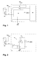
- FIG. 1 is a block diagram of a circuit arrangement 10 to control a controllable switch SW, which is shown in the Example a relay for the fuel pump (not shown) of a motor vehicle.
- This component SW the vehicle electrical system is switched on by the circuit arrangement 10 a line 12 is supplied with a control signal.
- the circuit arrangement comprises the definition of this control signal 10 a microcontroller MC, which is in operation provides an output signal at an output IO1 and inputs a circuit block 16 via a line 14, which at an output the control signal on the line 12 provides.
- the circuit arrangement 10 becomes an operating voltage of 12V then supplied via a supply connection Vbat 'if the circuit arrangement is to be put into operation.
- this operating voltage is the voltage of a (Not shown) starter battery of the motor vehicle, the in a manner known per se via an ignition lock when switching on the ignition to the supply connection Vbat ' becomes.
- the example shown shows a voltage when the engine starts output from 0V via line 12, so that by means of Switch SW the fuel pump is turned on.
- the microcontroller MC is equipped with a Voltage supplied by 5V, which at an output of a Voltage regulator 18 for both the microcontroller MC and circuit block 16 is also provided.
- a Voltage regulator 18 for both the microcontroller MC and circuit block 16 is also provided.
- the purpose of the voltage regulator 18 is, on the one hand, with the supply connection Vbat 'and on the other hand with a ground connection GND connected.
- the Voltage regulator 18 capable of operating the microcontroller to provide the required voltage of 5V, and the microcontroller MC starts after an initialization phase (of e.g. 50ms) its operation.
- the microcontroller MC then provides an output signal at its IO1 output ready, which causes the circuit block 16, this one Output signal corresponding control signal via the line 12 to turn on the switch SW.
- the circuit block 16 the drive signal based on the output signal of the Microcontrollers ready.
- the voltage regulator 18 on its output is no longer the one used to operate the microcontroller MC provide the required voltage of 5V and the Microcontroller MC goes into a reset mode, in which depending on the design of the microcontroller, the output signal at output IO1, for example, in a high-impedance State passes, so in this state the required Control signal not through the output signal of the microcontroller is defined.
- the operating voltage is too low ("Undervoltage"), which in practice by the process of Switching on a consumer with a very large one at the moment Power requirements can be caused and often only temporarily is provided, the circuit block 16 in the maintenance procedures described below of the control signal last defined by the microcontroller MC for a predetermined period of time. That period of time is dimensioned so that the bridging of this undefined Condition at least for a duration which equal to the sum of the expected duration in practice Undervoltage phase and the duration of the initialization phase of the microcontroller.
- FIG. 2 again shows that already described with reference to FIG. 1 Circuit arrangement 10, the structure of the Circuit block 16 is shown in detail, whereas other (to understand the function of circuit block 16 not essential) circuit parts are omitted. This omitted circuit parts are off in this example Fig. 1 can be seen.
- the circuit block 16 is constructed as follows.
- a second connection of resistor R2 is connected to the anode of the diode D1 via a resistor R3.
- This anode is also connected to the IO1 output of the microcontroller MC and a first connection of a capacitor C2 connected.
- the second connection of this capacitor is C2 connected to the GND (0V) ground connection.
- the collector of the Transistor T2 is connected to the gate of a MOS-FET T1, a first one Connection of a capacitor C1 and a first connection of a resistor R1 connected.
- the source of T1, the second port of C1 and the second port of R1 are also connected to the GND ground connection.
- the Drain from T1 is connected to line 12.
- the circuit arrangement 10 functions as described below.
- the circuit arrangement 10 via the supply connection Vbat '(ignition lock contact) supplied with the battery voltage of 12V.
- the output voltage of the voltage regulator 18 rises rapidly from 0V to 5V.
- This 5V operating voltage will both Microcontroller MC and the circuit block 16 supplied.
- the microcontroller MC remains initially, namely during the Duration of its initialization phase, still in a reset state, in which the output signal at output IO1 is undefined is.
- the Microcontroller MC a so-called tri-state output signal ready (0V, 5V, high impedance).
- the capacitor C2 is to this Unloading time and is via R3 and the parallel connection of R2 and the base-emitter diode of T2 slowly charged to 5V.
- T2, R2 and R3 may differ from what is shown Embodiment also combined in a single component be ("logic transistor").
- the one flowing into the base of T2 Share of this current switches T2 for a certain time one, so that during this time there is also a current through the collector flows from T2 and capacitor C1 from 0V to 5V charging. If this voltage across capacitor C1 the threshold voltage exceeds T1, T1 switches on.
- illustrated embodiment is a MOS-FET with a Threshold voltage of about 2.5V. The switch SW switches thus the fuel pump on.
- the normal operation of the circuit arrangement 10 begins when the microcontroller MC ends its initialization phase and the voltage level at the capacitor via its output IO1 C2 controlled to 0V. This keeps T2 on. The Voltage at C1 remains at 5V and T1 also remains switched on. The fuel pump switch SW thus remains switched on. In this state the output signal of the Microcontrollers MC the control signal for the switch SW.
- T2 turns on when the Ignition only conductive for a short time to the capacitor Charge C1 during this switch-on process. Then T2 switches however again. At that moment a slow one begins Discharge from C1 through resistor R1 so that the voltage slowly sinks at the gate of T1. The threshold voltage of T1 would fall below after about 200ms and the transistor T1 thus be switched off.
- the microcontroller normally ends MC, however, its initialization within one Time of about 50ms and takes over in time before falling below the threshold voltage at T1 is controlled via its Output IO1 and line 14. However, if, for example when starting the engine at low temperature, the battery voltage drops to 3V, the MC microcontroller is reset triggered.
- the reset state remains until the battery voltage supplied via the supply connection Vbat ' has reached 6V again and at the output of the voltage regulator 18 necessary for the operation of the microcontroller MC 5V can be provided. During this period remains T1, driven by the voltage at C1, but switched on.
- the undervoltage phase is thus through the circuit block 16 bridges so that the fuel pump switch SW remains switched on. If the microcontroller MC in time after the undervoltage phase has ended starts operating, it will turn its output IO1 to 0V control so that T1 remains on.
- additional control signals are generated for a predetermined period of time that of a digital Control unit generated control signal maintained if the digital control unit due to insufficient operating voltage fails (reset state).
- These "auxiliary signals” keep the last one specified by the digital control unit Control signal upright as long as this control unit in Reset condition is.
- the auxiliary signals go back to a "quiescent state", if the control unit is longer than a predetermined one Time remains in the reset state.
- FIG. 3 illustrates the behavior of the circuit arrangement 10 for an undervoltage duration of 100ms (between about 0s and 100ms) with timely takeover of control by the microcontroller (at the time 150ms).
- Fig. 3 shows above the course of the voltage V12 on line 12. This voltage drops very quickly from 12V when the ignition is switched on to 0V (switching on the fuel pump).
- FIG. 3 shows the profile of the voltage VC2 across the capacitor C2. This voltage VC2 increases when the ignition is switched on, see above that C2 is practically fully charged after 50ms. Essential is that at this point the charging process for capacitor C1 has already been terminated. If the mic rocontroller MC takes control again at about 150ms, the voltage VC2 quickly drops to 0V. This is the output voltage then provided by the MC MC at output IO1.
- FIG. 4 illustrates the behavior of the circuit arrangement 10 in the event of a fault in the microcontroller MC, which does so leads to the fact that the microcontroller is not in its reset state ended on time.
- Fig. 4 above shows the voltage again VC2 on capacitor C2, which in this case also has the timing of 150ms remains at 5V because of the microcontroller MC does not specify this voltage at this time.
- FIG. 4 center again shows the voltage VC1 on the capacitor C1, the continues to drop beyond the point in time of 150ms and finally the threshold voltage at a time of about 200ms falls below C1.
- Fig. 4 below shows again the Voltage V12 on line 12, in this case accordingly at around 200ms slowly rises again to 12V, because falling below the threshold voltage of T1 for switching off this transistor leads. By turning this off from T1 is an uncontrolled continued operation of the fuel pump prevented.
- FIG. 5 shows an alternative embodiment of the circuit arrangement 10. This second embodiment is for driving electrical components provided, which when switched on the ignition is not immediately triggered by a predefined control signal but only by the one specified by the microcontroller Output signal should be controlled.
- control output IO1
- this assigned only one circuit block 16 there is only one control output (IO1) and this assigned only one circuit block 16 is present, so could in an alternative, there are several control outputs a plurality of control outputs each with one Circuit block for maintaining the relevant output signal are provided during an undervoltage phase.
Landscapes
- Engineering & Computer Science (AREA)
- Mechanical Engineering (AREA)
- Automation & Control Theory (AREA)
- Control Of Direct Current Motors (AREA)
- Electric Propulsion And Braking For Vehicles (AREA)
- Combined Controls Of Internal Combustion Engines (AREA)
Applications Claiming Priority (2)
| Application Number | Priority Date | Filing Date | Title |
|---|---|---|---|
| US10/446,321 US6901326B2 (en) | 2003-05-28 | 2003-05-28 | Circuit layout and procedure to control at least one electrical component of a motor vehicle |
| US446321 | 2003-05-28 |
Publications (2)
| Publication Number | Publication Date |
|---|---|
| EP1482154A2 true EP1482154A2 (fr) | 2004-12-01 |
| EP1482154A3 EP1482154A3 (fr) | 2010-06-02 |
Family
ID=33131560
Family Applications (1)
| Application Number | Title | Priority Date | Filing Date |
|---|---|---|---|
| EP20040102214 Withdrawn EP1482154A3 (fr) | 2003-05-28 | 2004-05-19 | Circuit et méthode pour commander au moins un composant électrique d'un véhicule |
Country Status (2)
| Country | Link |
|---|---|
| US (1) | US6901326B2 (fr) |
| EP (1) | EP1482154A3 (fr) |
Families Citing this family (5)
| Publication number | Priority date | Publication date | Assignee | Title |
|---|---|---|---|---|
| US7591653B2 (en) * | 2006-09-08 | 2009-09-22 | Aees, Inc. | Modular power distribution center |
| US8209107B2 (en) | 2008-01-23 | 2012-06-26 | Hamilton Sundstrand Corporation | Electric motor for fuel pump with improved shutdown features |
| CN203267806U (zh) * | 2013-03-21 | 2013-11-06 | 比亚迪股份有限公司 | 一种电动汽车供电系统 |
| JP6332048B2 (ja) | 2015-01-14 | 2018-05-30 | 株式会社デンソー | 電子制御装置 |
| WO2021235733A1 (fr) * | 2020-05-20 | 2021-11-25 | 주식회사 엘지에너지솔루션 | Dispositif et procédé de commande de relais |
Citations (3)
| Publication number | Priority date | Publication date | Assignee | Title |
|---|---|---|---|---|
| US5038135A (en) | 1990-05-14 | 1991-08-06 | Chrysler Corporation | Sensor communications network, door latch mechanism therefor |
| DE10005778A1 (de) | 2000-02-10 | 2001-08-16 | Bosch Gmbh Robert | Schaltungsanordnung für einen Starter eines Kraftfahrzeug-Verbrennungsmotors |
| DE10219885A1 (de) | 2001-11-06 | 2003-05-22 | Mitsubishi Electric Corp | Vorrichtung zum Schützen eines Kraftfahrzeugs gegen unbefugten Betrieb |
Family Cites Families (8)
| Publication number | Priority date | Publication date | Assignee | Title |
|---|---|---|---|---|
| US4234920A (en) * | 1978-11-24 | 1980-11-18 | Engineered Systems, Inc. | Power failure detection and restart system |
| US4544924A (en) * | 1982-12-22 | 1985-10-01 | Rca Corporation | On-off arrangement in a microprocessor controlled remote transmitter for a consumer instrument |
| US5313112A (en) * | 1991-12-23 | 1994-05-17 | Ford Motor Company | Low voltage inhibiting circuit for a microcomputer |
| JP3246833B2 (ja) * | 1994-07-08 | 2002-01-15 | 株式会社日立製作所 | 自動車制御装置及び自動車制御方法 |
| US5651011A (en) * | 1995-06-01 | 1997-07-22 | Micron Technology, Inc. | Method and apparatus for initiating and controlling test modes within an integrated circuit |
| US5760625A (en) * | 1995-10-03 | 1998-06-02 | Ford Motor Company | Low cost microcomputer power supply with power on reset and low voltage inhibit functionality |
| DE69606783T2 (de) * | 1995-12-22 | 2000-11-16 | Thomson Consumer Electronics, Inc. | Rücksetzstellungsschaltung zur sicherstellung der korrekten rücksetzstellung für den fall zusammenbrechender stromversorgung |
| DE10106132A1 (de) | 2001-02-10 | 2002-08-14 | Philips Corp Intellectual Pty | Aufwachschaltung für ein elektrisches Gerät |
-
2003
- 2003-05-28 US US10/446,321 patent/US6901326B2/en not_active Expired - Fee Related
-
2004
- 2004-05-19 EP EP20040102214 patent/EP1482154A3/fr not_active Withdrawn
Patent Citations (3)
| Publication number | Priority date | Publication date | Assignee | Title |
|---|---|---|---|---|
| US5038135A (en) | 1990-05-14 | 1991-08-06 | Chrysler Corporation | Sensor communications network, door latch mechanism therefor |
| DE10005778A1 (de) | 2000-02-10 | 2001-08-16 | Bosch Gmbh Robert | Schaltungsanordnung für einen Starter eines Kraftfahrzeug-Verbrennungsmotors |
| DE10219885A1 (de) | 2001-11-06 | 2003-05-22 | Mitsubishi Electric Corp | Vorrichtung zum Schützen eines Kraftfahrzeugs gegen unbefugten Betrieb |
Also Published As
| Publication number | Publication date |
|---|---|
| US6901326B2 (en) | 2005-05-31 |
| EP1482154A3 (fr) | 2010-06-02 |
| US20040243297A1 (en) | 2004-12-02 |
Similar Documents
| Publication | Publication Date | Title |
|---|---|---|
| DE102009048850A1 (de) | Motorstartvorrichtung | |
| EP0714568B1 (fr) | Dispositif de commande pour un element de regulation de puissance d'une unite d'entrainement d'un vehicule | |
| DE112011102038T5 (de) | Leistungsversorgungssteuerschaltung und Leistungsversorgungssteuervorrichtung | |
| EP1901411B1 (fr) | Procédé destiné à la commande d'un moteur d'un outil à pile | |
| DE4329919A1 (de) | Verfahren zum Betreiben eines Verbrauchers in einem Fahrzeug | |
| DE102004036814B4 (de) | Vorrichtung zur Versorgung einer Kraftstoffpumpe einer Brennkraftmaschine eines Kraftfahrzeuges mit elektrischem Strom | |
| DE202014003691U1 (de) | Lastüberwachung mittels einer Überstromschutzeinrichtung | |
| DE102015207783B4 (de) | Gegen Überspannung geschütztes elektronisches Steuergerät | |
| DE102007001414B3 (de) | Schaltungsanordnung sowie Verfahren zum Betrieb einer induktiven Last | |
| DE102006034837B4 (de) | Maschinenanlasser und Maschinenstartverfahren | |
| DE102005051257A1 (de) | Motorsteuerung | |
| DE69202643T2 (de) | Steuervorrichtung für einen Anlasser eines Kraftfahrzeuges. | |
| EP3934942B1 (fr) | Appareil de commande de véhicule automobile, comportant une fonction de mise en circuit et d'arrêt pour au moins un consommateur électrique devant être commandé par l'appareil de commande de véhicule automobile | |
| WO2021224120A1 (fr) | Réseau de bord pour un véhicule à moteur et procédé pour faire fonctionner un réseau de bord | |
| EP1482154A2 (fr) | Circuit et méthode pour commander au moins un composant électrique d'un véhicule | |
| EP2131497B1 (fr) | Commutateur de semi-conducteur doté d'une commutation de court-circuit | |
| DE112017006826T5 (de) | Lichtbogenlöscheinrichtung für Gleichstromschalter | |
| EP1032950B1 (fr) | Circuit de decharge pour element de reglage capacitif | |
| EP1690326A1 (fr) | Ensemble circuit et procede de commande d'un consommateur inductif | |
| DE102010015095A1 (de) | Treiberschaltung für eine Last und Baugruppe aus Treiberschaltung und einer Last | |
| DE102014214156A1 (de) | Verfahren und Schaltungsanordnung zur Überprüfung einer Funktionsfähigkeit eines Halbleiterschalters eines Abschaltpfades | |
| DE10148646A1 (de) | Brennkraftmaschinensteuerung sowie Verfahren zum Betrieb einer Brennkraftmaschinensteuerung | |
| WO2024132521A1 (fr) | Système de protection d'une charge d'un système électrique embarqué basse tension | |
| DE19803851A1 (de) | Verfahren und Vorrichtung zur Überwachung eines Schaltmittels | |
| DE10314566A1 (de) | Ansteuerschaltung für piezoelektrische Bauteile |
Legal Events
| Date | Code | Title | Description |
|---|---|---|---|
| PUAI | Public reference made under article 153(3) epc to a published international application that has entered the european phase |
Free format text: ORIGINAL CODE: 0009012 |
|
| AK | Designated contracting states |
Kind code of ref document: A2 Designated state(s): AT BE BG CH CY CZ DE DK EE ES FI FR GB GR HU IE IT LI LU MC NL PL PT RO SE SI SK TR |
|
| AX | Request for extension of the european patent |
Extension state: AL HR LT LV MK |
|
| RAP1 | Party data changed (applicant data changed or rights of an application transferred) |
Owner name: SIEMENS VDO AUTOMOTIVE CORPORATION Owner name: CONTINENTAL AUTOMOTIVE GMBH |
|
| PUAL | Search report despatched |
Free format text: ORIGINAL CODE: 0009013 |
|
| AK | Designated contracting states |
Kind code of ref document: A3 Designated state(s): AT BE BG CH CY CZ DE DK EE ES FI FR GB GR HU IE IT LI LU MC NL PL PT RO SE SI SK TR |
|
| AX | Request for extension of the european patent |
Extension state: AL HR LT LV MK |
|
| 17P | Request for examination filed |
Effective date: 20101202 |
|
| AKX | Designation fees paid |
Designated state(s): DE FR SE |
|
| 17Q | First examination report despatched |
Effective date: 20110125 |
|
| STAA | Information on the status of an ep patent application or granted ep patent |
Free format text: STATUS: THE APPLICATION IS DEEMED TO BE WITHDRAWN |
|
| 18D | Application deemed to be withdrawn |
Effective date: 20160614 |