EP1482299A1 - Sensor und Verfahren zur Herstellung desselben - Google Patents
Sensor und Verfahren zur Herstellung desselben Download PDFInfo
- Publication number
- EP1482299A1 EP1482299A1 EP20040012423 EP04012423A EP1482299A1 EP 1482299 A1 EP1482299 A1 EP 1482299A1 EP 20040012423 EP20040012423 EP 20040012423 EP 04012423 A EP04012423 A EP 04012423A EP 1482299 A1 EP1482299 A1 EP 1482299A1
- Authority
- EP
- European Patent Office
- Prior art keywords
- test
- membrane
- test membrane
- reagent
- carrier
- Prior art date
- Legal status (The legal status is an assumption and is not a legal conclusion. Google has not performed a legal analysis and makes no representation as to the accuracy of the status listed.)
- Granted
Links
- 238000012360 testing method Methods 0.000 title claims abstract description 150
- 238000004519 manufacturing process Methods 0.000 title claims description 14
- 238000000034 method Methods 0.000 title claims description 13
- 239000012528 membrane Substances 0.000 claims abstract description 126
- 239000003153 chemical reaction reagent Substances 0.000 claims abstract description 58
- 238000006243 chemical reaction Methods 0.000 claims abstract description 31
- 239000007788 liquid Substances 0.000 claims abstract description 20
- 239000012491 analyte Substances 0.000 claims abstract description 19
- 229920000642 polymer Polymers 0.000 claims abstract description 17
- 230000003287 optical effect Effects 0.000 claims abstract description 6
- 239000000463 material Substances 0.000 claims description 20
- 239000000853 adhesive Substances 0.000 claims description 13
- 230000001070 adhesive effect Effects 0.000 claims description 13
- 238000005520 cutting process Methods 0.000 claims description 4
- 230000002209 hydrophobic effect Effects 0.000 claims description 3
- 229920001600 hydrophobic polymer Polymers 0.000 claims 1
- 239000000758 substrate Substances 0.000 description 11
- 229920000307 polymer substrate Polymers 0.000 description 9
- 239000008280 blood Substances 0.000 description 6
- 210000004369 blood Anatomy 0.000 description 6
- 239000008103 glucose Substances 0.000 description 6
- 238000003556 assay Methods 0.000 description 4
- 210000001124 body fluid Anatomy 0.000 description 4
- 239000010839 body fluid Substances 0.000 description 4
- 238000007598 dipping method Methods 0.000 description 4
- 238000012986 modification Methods 0.000 description 4
- 230000004048 modification Effects 0.000 description 4
- 230000008569 process Effects 0.000 description 4
- WQZGKKKJIJFFOK-GASJEMHNSA-N Glucose Natural products OC[C@H]1OC(O)[C@H](O)[C@@H](O)[C@@H]1O WQZGKKKJIJFFOK-GASJEMHNSA-N 0.000 description 3
- 230000008859 change Effects 0.000 description 3
- 238000004049 embossing Methods 0.000 description 3
- 239000012530 fluid Substances 0.000 description 3
- 238000010030 laminating Methods 0.000 description 3
- 238000005086 pumping Methods 0.000 description 3
- 239000012876 carrier material Substances 0.000 description 2
- HVYWMOMLDIMFJA-DPAQBDIFSA-N cholesterol Chemical compound C1C=C2C[C@@H](O)CC[C@]2(C)[C@@H]2[C@@H]1[C@@H]1CC[C@H]([C@H](C)CCCC(C)C)[C@@]1(C)CC2 HVYWMOMLDIMFJA-DPAQBDIFSA-N 0.000 description 2
- 238000010276 construction Methods 0.000 description 2
- 238000010924 continuous production Methods 0.000 description 2
- 238000000151 deposition Methods 0.000 description 2
- 238000003306 harvesting Methods 0.000 description 2
- 238000012806 monitoring device Methods 0.000 description 2
- 239000004033 plastic Substances 0.000 description 2
- 229920003023 plastic Polymers 0.000 description 2
- -1 polypropylene Polymers 0.000 description 2
- 210000003296 saliva Anatomy 0.000 description 2
- 210000002700 urine Anatomy 0.000 description 2
- 239000002699 waste material Substances 0.000 description 2
- LFQSCWFLJHTTHZ-UHFFFAOYSA-N Ethanol Chemical compound CCO LFQSCWFLJHTTHZ-UHFFFAOYSA-N 0.000 description 1
- 102000001554 Hemoglobins Human genes 0.000 description 1
- 108010054147 Hemoglobins Proteins 0.000 description 1
- 239000000020 Nitrocellulose Substances 0.000 description 1
- 239000004695 Polyether sulfone Substances 0.000 description 1
- 239000004698 Polyethylene Substances 0.000 description 1
- 239000004743 Polypropylene Substances 0.000 description 1
- 239000004793 Polystyrene Substances 0.000 description 1
- 238000010521 absorption reaction Methods 0.000 description 1
- 230000009471 action Effects 0.000 description 1
- 230000002411 adverse Effects 0.000 description 1
- 238000004458 analytical method Methods 0.000 description 1
- WQZGKKKJIJFFOK-VFUOTHLCSA-N beta-D-glucose Chemical compound OC[C@H]1O[C@@H](O)[C@H](O)[C@@H](O)[C@@H]1O WQZGKKKJIJFFOK-VFUOTHLCSA-N 0.000 description 1
- 239000000969 carrier Substances 0.000 description 1
- 239000013043 chemical agent Substances 0.000 description 1
- 235000012000 cholesterol Nutrition 0.000 description 1
- 238000004891 communication Methods 0.000 description 1
- 230000007423 decrease Effects 0.000 description 1
- 230000003247 decreasing effect Effects 0.000 description 1
- 238000013461 design Methods 0.000 description 1
- 239000003814 drug Substances 0.000 description 1
- 229940079593 drug Drugs 0.000 description 1
- 210000003722 extracellular fluid Anatomy 0.000 description 1
- IXZISFNWUWKBOM-ARQDHWQXSA-N fructosamine Chemical compound NC[C@@]1(O)OC[C@@H](O)[C@@H](O)[C@@H]1O IXZISFNWUWKBOM-ARQDHWQXSA-N 0.000 description 1
- 238000005470 impregnation Methods 0.000 description 1
- 238000003780 insertion Methods 0.000 description 1
- 230000037431 insertion Effects 0.000 description 1
- 230000001788 irregular Effects 0.000 description 1
- 239000000203 mixture Substances 0.000 description 1
- 229920001220 nitrocellulos Polymers 0.000 description 1
- 239000004417 polycarbonate Substances 0.000 description 1
- 229920000515 polycarbonate Polymers 0.000 description 1
- 229920006393 polyether sulfone Polymers 0.000 description 1
- 229920000573 polyethylene Polymers 0.000 description 1
- 239000002861 polymer material Substances 0.000 description 1
- 229920001155 polypropylene Polymers 0.000 description 1
- 229920002223 polystyrene Polymers 0.000 description 1
- 239000004800 polyvinyl chloride Substances 0.000 description 1
- 229920000915 polyvinyl chloride Polymers 0.000 description 1
- 239000011148 porous material Substances 0.000 description 1
- 244000062645 predators Species 0.000 description 1
- 230000035945 sensitivity Effects 0.000 description 1
- 238000007493 shaping process Methods 0.000 description 1
- 238000011144 upstream manufacturing Methods 0.000 description 1
Images


Classifications
-
- G—PHYSICS
- G01—MEASURING; TESTING
- G01N—INVESTIGATING OR ANALYSING MATERIALS BY DETERMINING THEIR CHEMICAL OR PHYSICAL PROPERTIES
- G01N33/00—Investigating or analysing materials by specific methods not covered by groups G01N1/00 - G01N31/00
- G01N33/48—Biological material, e.g. blood, urine; Haemocytometers
- G01N33/50—Chemical analysis of biological material, e.g. blood, urine; Testing involving biospecific ligand binding methods; Immunological testing
- G01N33/52—Use of compounds or compositions for colorimetric, spectrophotometric or fluorometric investigation, e.g. use of reagent paper and including single- and multilayer analytical elements
- G01N33/525—Multi-layer analytical elements
-
- A—HUMAN NECESSITIES
- A61—MEDICAL OR VETERINARY SCIENCE; HYGIENE
- A61B—DIAGNOSIS; SURGERY; IDENTIFICATION
- A61B5/00—Measuring for diagnostic purposes; Identification of persons
- A61B5/145—Measuring characteristics of blood in vivo, e.g. gas concentration or pH-value ; Measuring characteristics of body fluids or tissues, e.g. interstitial fluid or cerebral tissue
- A61B5/14532—Measuring characteristics of blood in vivo, e.g. gas concentration or pH-value ; Measuring characteristics of body fluids or tissues, e.g. interstitial fluid or cerebral tissue for measuring glucose, e.g. by tissue impedance measurement
-
- A—HUMAN NECESSITIES
- A61—MEDICAL OR VETERINARY SCIENCE; HYGIENE
- A61B—DIAGNOSIS; SURGERY; IDENTIFICATION
- A61B5/00—Measuring for diagnostic purposes; Identification of persons
- A61B5/145—Measuring characteristics of blood in vivo, e.g. gas concentration or pH-value ; Measuring characteristics of body fluids or tissues, e.g. interstitial fluid or cerebral tissue
- A61B5/1455—Measuring characteristics of blood in vivo, e.g. gas concentration or pH-value ; Measuring characteristics of body fluids or tissues, e.g. interstitial fluid or cerebral tissue using optical sensors, e.g. spectral photometrical oximeters
-
- G—PHYSICS
- G01—MEASURING; TESTING
- G01N—INVESTIGATING OR ANALYSING MATERIALS BY DETERMINING THEIR CHEMICAL OR PHYSICAL PROPERTIES
- G01N21/00—Investigating or analysing materials by the use of optical means, i.e. using sub-millimetre waves, infrared, visible or ultraviolet light
- G01N21/75—Systems in which material is subjected to a chemical reaction, the progress or the result of the reaction being investigated
- G01N21/77—Systems in which material is subjected to a chemical reaction, the progress or the result of the reaction being investigated by observing the effect on a chemical indicator
- G01N21/78—Systems in which material is subjected to a chemical reaction, the progress or the result of the reaction being investigated by observing the effect on a chemical indicator producing a change of colour
-
- G—PHYSICS
- G01—MEASURING; TESTING
- G01N—INVESTIGATING OR ANALYSING MATERIALS BY DETERMINING THEIR CHEMICAL OR PHYSICAL PROPERTIES
- G01N27/00—Investigating or analysing materials by the use of electric, electrochemical, or magnetic means
- G01N27/26—Investigating or analysing materials by the use of electric, electrochemical, or magnetic means by investigating electrochemical variables; by using electrolysis or electrophoresis
- G01N27/28—Electrolytic cell components
- G01N27/30—Electrodes, e.g. test electrodes; Half-cells
- G01N27/327—Biochemical electrodes, e.g. electrical or mechanical details for in vitro measurements
- G01N27/3271—Amperometric enzyme electrodes for analytes in body fluids, e.g. glucose in blood
- G01N27/3272—Test elements therefor, i.e. disposable laminated substrates with electrodes, reagent and channels
-
- B—PERFORMING OPERATIONS; TRANSPORTING
- B01—PHYSICAL OR CHEMICAL PROCESSES OR APPARATUS IN GENERAL
- B01L—CHEMICAL OR PHYSICAL LABORATORY APPARATUS FOR GENERAL USE
- B01L3/00—Containers or dishes for laboratory use, e.g. laboratory glassware; Droppers
- B01L3/50—Containers for the purpose of retaining a material to be analysed, e.g. test tubes
- B01L3/502—Containers for the purpose of retaining a material to be analysed, e.g. test tubes with fluid transport, e.g. in multi-compartment structures
- B01L3/5027—Containers for the purpose of retaining a material to be analysed, e.g. test tubes with fluid transport, e.g. in multi-compartment structures by integrated microfluidic structures, i.e. dimensions of channels and chambers are such that surface tension forces are important, e.g. lab-on-a-chip
- B01L3/502707—Containers for the purpose of retaining a material to be analysed, e.g. test tubes with fluid transport, e.g. in multi-compartment structures by integrated microfluidic structures, i.e. dimensions of channels and chambers are such that surface tension forces are important, e.g. lab-on-a-chip characterised by the manufacture of the container or its components
-
- Y—GENERAL TAGGING OF NEW TECHNOLOGICAL DEVELOPMENTS; GENERAL TAGGING OF CROSS-SECTIONAL TECHNOLOGIES SPANNING OVER SEVERAL SECTIONS OF THE IPC; TECHNICAL SUBJECTS COVERED BY FORMER USPC CROSS-REFERENCE ART COLLECTIONS [XRACs] AND DIGESTS
- Y10—TECHNICAL SUBJECTS COVERED BY FORMER USPC
- Y10T—TECHNICAL SUBJECTS COVERED BY FORMER US CLASSIFICATION
- Y10T156/00—Adhesive bonding and miscellaneous chemical manufacture
- Y10T156/10—Methods of surface bonding and/or assembly therefor
- Y10T156/1052—Methods of surface bonding and/or assembly therefor with cutting, punching, tearing or severing
- Y10T156/1054—Methods of surface bonding and/or assembly therefor with cutting, punching, tearing or severing and simultaneously bonding [e.g., cut-seaming]
Definitions
- the present invention relates generally to liquid sample monitoring devices and, more particularly, to the manufacture and design of a test sensor for use in determining the concentration of an analyte in a liquid sample.
- Test sensors are often used in assays for determining the concentration of an analyte in a liquid sample.
- a liquid sample is deposited in a reaction area of the test sensor that includes a reagent.
- the sample and the reagent mix producing a measurable reaction indicative the concentration of the analyte in the liquid sample.
- the reaction is measured with a test device that receives the test sensor.
- Test sensors are also used be used for determining the concentration of or determining the presence of a various other analytes (e.g ., fructosamine, hemoglobin, cholesterol, glucose, alcohol, drugs, etc.) in a variety of body fluids (e.g ., blood, interstitial fluid, saliva, urine, etc .). Test sensors including appropriate reagents can be used in the harvesting of most any liquid sample for the determination of the concentration of an analyte in that sample.
- a various other analytes e.g ., fructosamine, hemoglobin, cholesterol, glucose, alcohol, drugs, etc.
- body fluids e.g ., blood, interstitial fluid, saliva, urine, etc .
- the type of reagent implemented in the test sensor depends on the type of measuring used. For example, in a colorimeteric assay, the color change of a reaction area containing a reagent following contact with the sample is measured to determine the concentration of the analyte of interest in the sample. The degree of color change is measured using an optical sensor(s) that converts the degree of color change to electrical signals that are evaluated with diagnostic equipment. For example, the optical device may measure the amount of light reflected from, or transmitted through, the reaction area. In other embodiments of the present invention, the amount of infrared light absorbed by the reaction of the analyte in the sample and the reagent is measured. Colorimetric testing is described in detail in U.S. Patent No.
- the reagent that is used in the test sensor is a chemical agent that is costly to produce. Thus, it is desirable to limit the amount of reagent used and to reduce any waste of the reagent.
- Current manufacturing processes waste the costly reagent by impregnating more test membrane material than necessary.
- the test sensors include a membrane that is impregnated with the reagent during manufacturing by dipping, which e ntails submerging a t est membrane s heet in t he r eagent.
- T est sensor disks i.e., cut sections sized for inclusion in a test sensor
- picking and placing the reagent impregnated sensor disks into the test sensor introduces material handling issues due to the sensitivity of the reagent which impacts the complexity and cost of the test sensor manufacturing process.
- an optical-based test sensor for use in the determination of an analyte in a liquid sample.
- the test sensor includes a base, a polymer carrier, and a test membrane.
- the base has a capillary c hannel formed in a surface of the base that is adapted to move a liquid sample from an inlet to a reaction area formed in the base.
- the polymer carrier has a lower surface adhered to the surface of the base and is disposed over at least a portion of the capillary channel.
- the test membrane which contains a reagent, is adhered to the lower surface of the polymer carrier and extends from the polymer carrier into the reaction area.
- test sensor 10 is shown according to one embodiment of the present invention.
- the test sensor 10 is used in the harvesting and analysis of a liquid sample for determining the presence or concentration of an analyte in the liquid sample.
- the test sensor 10 includes a test membrane disk 12 having a reagent 14 disposed therein.
- the test membrane disk 12 is adhered to the underside (as viewed in FIG. 1) of a carrier strip 16.
- the carrier strip 16 is laminated to a base 18 of the test sensor such that the test membrane disk 12 downwardly extends into a reaction area 21 of a capillary channel 20 formed in the base 18.
- the carrier strip 16 forms a lid over the capillary channel 20.
- a liquid sample is harvested by positioning an inlet 22 of the capillary channel 20 adjacent the sample.
- the sample is moved, via capillary action, from the inlet 22 to the reaction area 21 where an analyte in the sample reacts with the reagent disposed in the test membrane 12.
- the carrier 16 is positioned on the base 18 such that the upstream end of the capillary channel 20 remains uncovered to form a vent 23 to facilitate movement of the fluid sample in the capillary channel.
- the analyte of interest e.g., glucose
- the capillary channel 20 is sized to provide underfill protection so that a required volume of sample is delivered to the reaction area 21. Additionally, or alternatively, the capillary channel 20 is widened to increase the lateral flow of the sample to the test membrane disk 12 by enlarging the surface area of the test membrane disk 12 periphery exposed to the sample flow in the capillary channel 20. In yet other embodiments, the test sensor 10 base 18 is dimensioned to create a small gap between the side walls of the capillary channel 20 and the edges of the test membrane, the bottom wall of the capillary channel 20 and the bottom surface of the membrane, or both.
- gaps provide a clearance to allow the flow of the sample across the bottom surface and edges of the test membrane disk 12, which decreases saturation time and uniformity of the assay.
- These gaps between the edge and bottom of the test membrane disk 12 and the capillary channel 20 can range between a bout 0.0005 inch (about 0.0127 mm) and about 0.001 inch (about 0.0254 mm).
- a wicking membrane or mesh is attached to the test membrane 12 to draw and diffuse the sample across the test membrane 12 to increase the flow of the sample across the test membrane disk 12.
- the test membranes 12 are made of a hydrophilic polyethersulfone material having pore sizes ranging from about 0.2 to about 8 micrometers.
- the Presense membrane and the Predator® membrane are two examples of commercially available test membranes that may be used in various embodiments of the present invention.
- the test membrane may be made of a nitrocellulose material. While the test membrane disks 12 shown in FIG. 1 are disk-shaped, the test membranes can be of any shape in alternative embodiments of the present invention.
- the carrier 16 and the base 18 are both constructed of plastic. According to one embodiment of the present invention, the carrier 16 and the base 18 are constructed of plastic having a surface tension of less than about 45 milli-Newtons per meter such as polystyrene, polypropylene, polyethylene, p olyethylene t erephthalate, polycarbonate, and polyvinyl chloride, for example.
- the carrier 16 and base 18 are constructed of a somewhat hydrophobic material so as not to absorb the reagent 14 or the sample that moves through the capillary channel 20 formed in the base 18 according to one embodiment of the present invention. Further, these materials are not adversely affected by the liquid samples (e.g., blood, urine, or saliva) to be tested.
- the carrier 16 is substantially optically transparent allowing the reaction between the analyte in the sample and the reagent to be optically measured through the carrier 16.
- the dimensions of the test sensor 10 are as follows.
- the capillary channel 20 has a width ranging between about 1 mm and about 2 mm, with the reaction area 21 having a diameter of about 3-5 mm.
- the test membrane disk 12 has a diameter of about 2.5 to about 3.5 mm. In other embodiments, the test membrane disk 12 has a diameter of about 1 to about 2 mm, the reaction area 21 has a diameter of about 1.5 to about 2.5 mm, and the capillary channel 20 has a width of 0.75 to about 1 mm.
- the reaction area 21 has a depth of about 0.10 to about 0.20 mm, leaving clearance between the bottom surface of the reaction area 21 and the test membrane disk 12. This clearance increases fluid sample flow across the bottom surface of the test membrane disk 12.
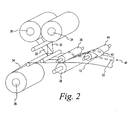
- the membrane material i.e. , the material from which test membrane disks 12 are cut
- the carrier material i.e., the material from which the carrier 16 is cut
- An adhesive liner for adhering the membrane material to the carrier material, is disposed on a third roll 28.
- the adhesive liner that adheres the test membrane disk 12 to the carrier 16 comprises a substantially optically clear adhesive for permitting the test membrane disk 12 to be read through the substantially optically clear carrier 16.
- a test membrane web 30 from the first roll 24, an adhesive liner web 32 from the third roll 28, and a carrier web 34 from the third roll 26 are fed between a cylindrical, rotating die 36 and counter pressure roller 38 that crush-cut the test membrane web 30 and the adhesive liner web 32 onto the carrier web 34.
- the carrier web 34 is not cut resulting in a continuous membrane/carrier strip 40 having individual, cut test membrane disks 12 adhered thereto and spaced apart by a predetermined distance.
- the excess adhesive liner material and test membrane material 42 are lifted from the membrane/carrier strip 40 by a withdraw roller 44.
- the membrane/carrier strip 40 is dipped into a tank 50 containing a liquid reagent for impregnating the test membrane disks 12 with the reagent 14.
- the test membrane disks 12 absorb the reagent 14.
- the carrier 34 does not absorb any of the reagent 14 due to its hydrophobic nature. Thus, only the test membrane disks 12 absorb the reagent 14.
- test membrane disks 12 Only the portions of the membrane material to be used (e.g. , the test membrane disks 12) and not any excess membrane material absorb the costly reagent because the test membrane disks 12 have been cut to the appropriate size for insertion into a test sensor base 18 (FIG. 1) prior to being impregnated with the reagent.
- further measures may be implemented for controlling the amount of reagent 14 absorbed by the test membrane disks 12 in alternative embodiments of the present invention.
- the speed at which the membrane/carrier strip 40 is advanced into the tank 50 of reagent 14 can be varied to control the amount of time each test membrane disks 12 spends dipped in the reagent 14.
- each test membrane disk 12 The degree of impregnation of each test membrane disk 12 is directly proportional to the amount of time that the test membrane disk 12 is dipped into the reagent 14. Additionally, apertures may be formed in the carrier web 34 so that the test membrane disks 12 absorb the reagent 14 from both sides. In such an embodiment, the time in which each test membrane disk 12 is dipped into the reagent 14 may be decreased because each test membrane d isk 12 is absorbing reagent 14 from both sides which increases the test membrane disk's 12 rate of reagent 14 absorption.
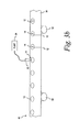
- FIG. 3b an alternative embodiment for disposing the reagent 14 on the test membrane disks 12 is illustrated.
- the membrane/carrier strip 40 is moved past a nozzle 52, via a plurality of rollers 53, that is in fluid communication with a pump 54 for pumping the reagent 14 though the nozzle 52.
- the nozzle 52 directs the reagent 14 onto the test membrane disks 12.
- the pump 54 controls the amount of reagent 14 deposited on each test membrane disk 12.
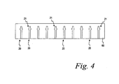
- a polymer substrate 60 is provided from which the test sensor bodies 18 (FIG. 1) are formed.
- the bodies 18 are constructed of a polymer material so that the liquid sample to be analyzed is not absorbed by the test sensor base 18.
- a plurality of capillary channels 20, including the reaction areas 21, are formed in the polymer substrate 60.
- the capillary channels 20 are formed in the substrate 60 by any one of a variety of known manufacturing processes including flat bed embossing or rotary embossing.
- the process of embossing the capillary channel 20 into the polymer substrate 60 is performed using a continuous web process, similar to the method described above for cutting the test membrane disks 12 from the web of membrane material 12 (FIG. 2).
- a long length of the substrate may be formed in a reel format or in a sheet format having a specific number ( e.g. , 5, 10 or 20) of capillary channels formed therein.
- the polymer substrate 60 having the capillary channels 20 formed therein is attached to the membrane/carrier strip 40 comprising the carrier 16 and the plurality of test membrane disks 12 disposed thereon.
- the membrane/carrier strip 40 is disposed on the polymer substrate 60 such that the test membrane disks 12 extends into the reaction areas 21 of the capillary channels 20 formed in the polymer substrate 60.
- the membrane/carrier strip 40 is laminated to the substrate 60 using an adhesive.
- the adhesive may be applied to the polymer substrate 60 prior to or subsequent to forming the capillary channels 20 in the substrate 60.
- the adhesive used to laminate the membrane/carrier strip 40 to the polymer substrate is heat and pressure sensitive. An example of an adhesive for use with the present invention is described in U.S. Patents Nos. 5,759,364 and 5,798,031, each of which is incorporated herein by reference in its entirety.
- a continuous process for laminating the membrane/carrier strip 40 to the polymer substrate 60 is illustrated according to one embodiment of the present invention.
- the substrate 60 and the membrane/carrier strip 40 are fed between a pair of rollers 70, 72 for continuously laminating the substrate 60 and the membrane/carrier strip 40 together.
- the capillary channels 20 are formed in a length of substrate 60 that is fed between rollers 70, 72 along with the membrane/carrier strip 40, wherein the membrane/carrier strip 40 is fed directly from the dipping process illustrated in FIG. 2 for forming a continuous length 76 of test sensors 10.
- non-continuous sheets of test sensors 10 e.g., 5, 10, or 15 test sensors
- FIG. 5 non-continuous sheets of test sensors 10 (e.g., 5, 10, or 15 test sensors) such as shown in FIG. 5, are laminated to a substrate 60 having the same number of capillary channels 20 formed therein.
- individual test sensors 10 are cut from a length 80 a plurality of test sensors 10.
- the test sensors 10 are cut from the length 80 of test sensors 10 using a stamping process.
- the length 80 is fed into a stamping die 82 which contains a die to cut out the individual test sensors 10. After stamping, the individual test sensors are packaged.
- the test sensors 10 are cut from the length 80 of test sensors 10 using a blade, rather than a stamping die.
- the manufacturing steps described in connection with FIGS. 2-7 may be part of a continuous manufacturing process wherein the stages are disposed along an manufacturing line.
- the membrane/carrier strip 40 formed as described in connection with FIG. 2 may be fed directly into the reagent t ank 50 discussed inconnection with F IG. 3a, or past the nozzle as described in connection with FIG. 3b.
- the various manufacturing stages of FIGS. 2-7 may be implemented in a non-continuous processes.
- a reel of the membrane/carrier strip 40 may be formed (FIG. 2) and then that reel is later fed into the reagent tank 50 discussed in connection with FIG. 3a.
- the reagent is applied to the test membrane disks 12 of the test sensors 10 by pumping the reagent 14 o nto t he t est m embrane d isks 12.
- the test membranes disks 12 are die-cut onto the polymer carriers 14 as described above in connection with FIG. 2.
- the carrier/membrane strip 40 is advanced past a reagent pump 54 as illustrated in FIG. 3b for depositing a predetermined amount of reagent 14 onto each of the test membrane disks 12.
- the amount of reagent 14 deposited onto each the test membrane 12 is controlled by the pump.
- the reagent is deposited or "ink-jetted" onto the test membranes by use of a plurality of piezoelectric controlled nozzles as are commonly used for depositing ink on paper in ink jet printers.
- test s ensor 10 has been d escribed thus far as having a two piece construction (i.e., a base 18 and a carrier 16) with the a capillary channel 20 formed in the base
- the test sensor can be have a three piece construction with the capillary channel c ut in a middle piece in alternative e mbodiments o f the present invention.
- a flat base, a generally U-shaped middle layer, and a flat lid are adhered together.
- the side walls of the capillary channel are formed by the interior of the U-shaped middle layer.
- a test membrane disk which is attached to the lid as described in connection with FIG. 1, is positioned within the closed end of the U-shaped middle layer and the open end of the U-shaped middle layer forms the inlet of the capillary channel.
- a reel 90 of the membrane/carrier strip 40 formed as described in c onnection w ith F IG. 2 is disposed with a dispensing cartridge 92 for dispensing test membrane disks 94 impregnated with a reagent attached to a carrier 96 one at a time.
- the cartridge 92 includes a cutting means (e.g. , a sharp or serrated edge) for cutting the carrier 96 for dispensing one test membrane disk 94 at a time.
- the carrier 96 is perforated between test membrane disks 94 during manufacturing to facilitate the tearing off of a single test membrane disk 94 from the reel 90.
- the individually dispensed test membrane disks 94 can be used with a top-fill device for determining the concentration of an analyst in a liquid sample according to an alternative embodiment of the present invention.
- a reel 100 of the membrane/carrier strip 40 formed as described in connection with FIG. 2 is disposed with a dispensing cartridge 102 for dispensing test membrane disks 104 impregnated with a r eagent attached to a carrier 106 one at a time, similar to that described in connection with FIG. 8.
- a collecting cartridge 110 collects the used test membrane disks 104.
- the dispensing and collecting cartridges 102 and 110 are implemented in a top-fill blood monitoring device wherein, for a example, a user places a blood sample (or other body fluid sample) on a test membrane disk 1 04 dispensed from the d ispensing cartridge 1 02.
- the top-fill device includes a light source 114 for illuminating the test membrane disk having a sample deposited thereon and a light detector 116 for measuring light reflected from the reaction of the analyte in the body fluid and the reagent on the test membrane disk 12 as is known in the art for determining the concentration of the analyte in the body fluid.
Landscapes
- Health & Medical Sciences (AREA)
- Life Sciences & Earth Sciences (AREA)
- Physics & Mathematics (AREA)
- Chemical & Material Sciences (AREA)
- Engineering & Computer Science (AREA)
- Pathology (AREA)
- Immunology (AREA)
- Molecular Biology (AREA)
- General Health & Medical Sciences (AREA)
- Hematology (AREA)
- Biomedical Technology (AREA)
- Biophysics (AREA)
- General Physics & Mathematics (AREA)
- Biochemistry (AREA)
- Analytical Chemistry (AREA)
- Optics & Photonics (AREA)
- Heart & Thoracic Surgery (AREA)
- Veterinary Medicine (AREA)
- Urology & Nephrology (AREA)
- Public Health (AREA)
- Animal Behavior & Ethology (AREA)
- Chemical Kinetics & Catalysis (AREA)
- Surgery (AREA)
- Medical Informatics (AREA)
- Cell Biology (AREA)
- Biotechnology (AREA)
- Spectroscopy & Molecular Physics (AREA)
- Electrochemistry (AREA)
- Medicinal Chemistry (AREA)
- Microbiology (AREA)
- Food Science & Technology (AREA)
- Plasma & Fusion (AREA)
- Emergency Medicine (AREA)
- Investigating Or Analysing Materials By The Use Of Chemical Reactions (AREA)
- Investigating Or Analysing Biological Materials (AREA)
Priority Applications (1)
| Application Number | Priority Date | Filing Date | Title |
|---|---|---|---|
| EP10172250A EP2314376A1 (de) | 2003-05-29 | 2004-05-26 | Testsensor und Herstellungsverfahren dafür |
Applications Claiming Priority (2)
| Application Number | Priority Date | Filing Date | Title |
|---|---|---|---|
| US47370303P | 2003-05-29 | 2003-05-29 | |
| US473703P | 2003-05-29 |
Publications (2)
| Publication Number | Publication Date |
|---|---|
| EP1482299A1 true EP1482299A1 (de) | 2004-12-01 |
| EP1482299B1 EP1482299B1 (de) | 2010-09-01 |
Family
ID=33131951
Family Applications (2)
| Application Number | Title | Priority Date | Filing Date |
|---|---|---|---|
| EP04012423A Expired - Lifetime EP1482299B1 (de) | 2003-05-29 | 2004-05-26 | Sensor und Verfahren zur Herstellung desselben |
| EP10172250A Withdrawn EP2314376A1 (de) | 2003-05-29 | 2004-05-26 | Testsensor und Herstellungsverfahren dafür |
Family Applications After (1)
| Application Number | Title | Priority Date | Filing Date |
|---|---|---|---|
| EP10172250A Withdrawn EP2314376A1 (de) | 2003-05-29 | 2004-05-26 | Testsensor und Herstellungsverfahren dafür |
Country Status (6)
| Country | Link |
|---|---|
| US (2) | US8153081B2 (de) |
| EP (2) | EP1482299B1 (de) |
| JP (1) | JP2004354388A (de) |
| AU (1) | AU2004202232A1 (de) |
| CA (1) | CA2468472A1 (de) |
| DE (1) | DE602004028894D1 (de) |
Cited By (5)
| Publication number | Priority date | Publication date | Assignee | Title |
|---|---|---|---|---|
| DE102004046366A1 (de) * | 2004-07-15 | 2006-02-09 | Levin, Felix, Dr. | Universell einsetzbare Testvorrichtung zur schnellen Analysen von Flüssigkeiten |
| WO2006044084A1 (en) * | 2004-09-20 | 2006-04-27 | Bayer Healthcare Llc | Blood glucose sensor dispensing instrument having a serrated knife |
| WO2008051407A3 (en) * | 2006-10-24 | 2008-12-31 | Abbott Diabetes Care Inc | Embossed cell analyte sensor and methods of manufacture |
| CN103234962A (zh) * | 2013-05-09 | 2013-08-07 | 董建国 | 一种阴道微生态环境传感器及其制作方法 |
| EP2907573A1 (de) * | 2014-02-14 | 2015-08-19 | Roche Diagnostics GmbH | Verfahren und Herstellungsvorrichtung zur Herstellung von mindestens einer analytischen Vorrichtung |
Families Citing this family (15)
| Publication number | Priority date | Publication date | Assignee | Title |
|---|---|---|---|---|
| US7280201B2 (en) * | 2004-12-17 | 2007-10-09 | Avago Technologies General Ip Pte Ltd | Sensor having integrated light detector and/or light source |
| EP1717585B1 (de) | 2005-04-28 | 2013-01-16 | FUJIFILM Corporation | Mikrochip und Analyseverfahren unter Verwendung desselben |
| JP2006308419A (ja) * | 2005-04-28 | 2006-11-09 | Fuji Photo Film Co Ltd | マイクロチップ及びそれを用いた分析方法 |
| CA2798716A1 (en) | 2011-12-13 | 2013-06-13 | Endochoice Innovation Center Ltd. | Removable tip endoscope |
| MX2015016017A (es) * | 2013-05-22 | 2016-06-21 | Imec Vzw | Dispositivo de analisis de fluido compacto y metodos para fabricarlo. |
| EP2811299A1 (de) | 2013-06-07 | 2014-12-10 | Roche Diagniostics GmbH | Testelement zur Detektion von mindestens einem Analyten in einer Körperflüssigkeit |
| US10101342B2 (en) | 2014-02-12 | 2018-10-16 | Church & Dwight Co., Inc. | Devices and methods for electronic analyte assaying |
| JP2015232550A (ja) * | 2014-05-13 | 2015-12-24 | アークレイ株式会社 | センサ体、センサ体の製造方法及びセンサカートリッジ |
| PL3356546T3 (pl) * | 2015-09-29 | 2020-11-16 | Polymer Technology Systems, Inc. | Systemy opraw paska testowego z bocznym przepływem |
| EP3559664B1 (de) | 2016-12-23 | 2020-12-09 | Radiometer Medical ApS | Mehrfach verwendbare sensoranordnung für körperflüssigkeiten |
| US11467069B2 (en) * | 2017-01-05 | 2022-10-11 | Shimadzu Corporation | Sampling chip dividing instrument |
| EP3409362B1 (de) * | 2017-05-31 | 2024-04-03 | Roche Diabetes Care GmbH | Verfahren zur herstellung eines testelementes zur erfassung einer analyte in einer körperflüssigkeit, testelement und verfahren zur verwendung |
| CN111323573B (zh) * | 2020-03-02 | 2025-07-29 | 欧蒙医学诊断(中国)有限公司 | 一种加样指示条及带有加样指示条的温育盘 |
| WO2023070567A1 (zh) * | 2021-10-29 | 2023-05-04 | 京东方科技集团股份有限公司 | 检测芯片及其制备方法 |
| US20230312209A1 (en) * | 2022-04-05 | 2023-10-05 | 10X Genomics, Inc. | Blister packs and uses thereof |
Citations (8)
| Publication number | Priority date | Publication date | Assignee | Title |
|---|---|---|---|---|
| US5518689A (en) | 1995-09-05 | 1996-05-21 | Bayer Corporation | Diffused light reflectance readhead |
| US5611999A (en) | 1995-09-05 | 1997-03-18 | Bayer Corporation | Diffused light reflectance readhead |
| US5723284A (en) | 1996-04-01 | 1998-03-03 | Bayer Corporation | Control solution and method for testing the performance of an electrochemical device for determining the concentration of an analyte in blood |
| US5962215A (en) | 1996-04-05 | 1999-10-05 | Mercury Diagnostics, Inc. | Methods for testing the concentration of an analyte in a body fluid |
| US6181417B1 (en) | 1998-04-20 | 2001-01-30 | Bayer Corporation | Photometric readhead with light-shaping plate |
| US6206841B1 (en) | 1996-12-06 | 2001-03-27 | Abbott Laboratories | Method and apparatus for obtaining blood for diagnostic tests |
| EP1203823A1 (de) | 2000-11-01 | 2002-05-08 | Roche Diagnostics GmbH | Biosensor |
| US20020168290A1 (en) | 2002-05-09 | 2002-11-14 | Yuzhakov Vadim V. | Physiological sample collection devices and methods of using the same |
Family Cites Families (37)
| Publication number | Priority date | Publication date | Assignee | Title |
|---|---|---|---|---|
| US4756884A (en) | 1985-08-05 | 1988-07-12 | Biotrack, Inc. | Capillary flow device |
| US4761381A (en) * | 1985-09-18 | 1988-08-02 | Miles Inc. | Volume metering capillary gap device for applying a liquid sample onto a reactive surface |
| US4935346A (en) * | 1986-08-13 | 1990-06-19 | Lifescan, Inc. | Minimum procedure system for the determination of analytes |
| US5049487A (en) * | 1986-08-13 | 1991-09-17 | Lifescan, Inc. | Automated initiation of timing of reflectance readings |
| DE3630999A1 (de) * | 1986-09-12 | 1988-03-17 | Boehringer Mannheim Gmbh | Mehrschichtiger testtraeger |
| US4753776A (en) | 1986-10-29 | 1988-06-28 | Biotrack, Inc. | Blood separation device comprising a filter and a capillary flow pathway exiting the filter |
| US4895798A (en) * | 1987-11-13 | 1990-01-23 | Miles, Inc. | Test devices for determination of occult blood |
| US5472671A (en) * | 1989-04-26 | 1995-12-05 | Nilsson; Sven-Erik | Cuvette |
| US6395227B1 (en) * | 1989-08-28 | 2002-05-28 | Lifescan, Inc. | Test strip for measuring analyte concentration over a broad range of sample volume |
| EP0443231B1 (de) | 1990-02-22 | 1995-11-08 | Editek, Inc. | Mehrschicht-Testvorrichtung zur Bestimmung von Substanzen in Flüssigkeiten |
| JPH05157745A (ja) | 1991-12-09 | 1993-06-25 | Dainippon Printing Co Ltd | 検査体 |
| US6156270A (en) * | 1992-05-21 | 2000-12-05 | Biosite Diagnostics, Inc. | Diagnostic devices and apparatus for the controlled movement of reagents without membranes |
| US5843691A (en) * | 1993-05-15 | 1998-12-01 | Lifescan, Inc. | Visually-readable reagent test strip |
| DE4326339A1 (de) * | 1993-08-05 | 1995-02-09 | Boehringer Mannheim Gmbh | System zur Analyse von Probenflüssigkeiten |
| US5700695A (en) * | 1994-06-30 | 1997-12-23 | Zia Yassinzadeh | Sample collection and manipulation method |
| DE19523049A1 (de) * | 1995-06-24 | 1997-01-02 | Boehringer Mannheim Gmbh | Mehrschichtiges Analysenelement zur Bestimmung eines Analyten in einer Flüssigkeit |
| DE19629656A1 (de) * | 1996-07-23 | 1998-01-29 | Boehringer Mannheim Gmbh | Diagnostischer Testträger mit mehrschichtigem Testfeld und Verfahren zur Bestimmung von Analyt mit dessen Hilfe |
| JP2953418B2 (ja) | 1997-01-09 | 1999-09-27 | 日本電気株式会社 | 生化学分析装置 |
| US5759364A (en) | 1997-05-02 | 1998-06-02 | Bayer Corporation | Electrochemical biosensor |
| US5798031A (en) | 1997-05-12 | 1998-08-25 | Bayer Corporation | Electrochemical biosensor |
| US6300138B1 (en) * | 1997-08-01 | 2001-10-09 | Qualigen, Inc. | Methods for conducting tests |
| DE19753847A1 (de) * | 1997-12-04 | 1999-06-10 | Roche Diagnostics Gmbh | Analytisches Testelement mit Kapillarkanal |
| JP3761698B2 (ja) * | 1997-12-24 | 2006-03-29 | 理想科学工業株式会社 | 孔版印刷機 |
| DE19815684A1 (de) * | 1998-04-08 | 1999-10-14 | Roche Diagnostics Gmbh | Verfahren zur Herstellung von analytischen Hilfsmitteln |
| US6521182B1 (en) | 1998-07-20 | 2003-02-18 | Lifescan, Inc. | Fluidic device for medical diagnostics |
| US6162397A (en) * | 1998-08-13 | 2000-12-19 | Lifescan, Inc. | Visual blood glucose test strip |
| CA2254223A1 (en) * | 1998-11-16 | 2000-05-16 | Biophys, Inc. | Device and method for analyzing a biologic sample |
| US6368563B1 (en) * | 1999-03-12 | 2002-04-09 | Integ, Inc. | Collection well for body fluid tester |
| JP2001272399A (ja) | 2000-01-21 | 2001-10-05 | Wako Pure Chem Ind Ltd | 多項目試験具その製造方法及び試験具測定装置 |
| US6403037B1 (en) * | 2000-02-04 | 2002-06-11 | Cepheid | Reaction vessel and temperature control system |
| US6776888B2 (en) | 2000-07-31 | 2004-08-17 | Matsushita Electric Industrial Co., Ltd. | Biosensor |
| JP3475228B2 (ja) * | 2000-10-26 | 2003-12-08 | 株式会社スズケン | 微量検体の分析に用いる酵素試験紙を配設したキャピラリー用具、および測定方法 |
| US7776608B2 (en) * | 2001-07-09 | 2010-08-17 | Bayer Healthcare Llc | Volume meter testing device and method of use |
| US6949297B2 (en) * | 2001-11-02 | 2005-09-27 | 3M Innovative Properties Company | Hybrid adhesives, articles, and methods |
| US6723500B2 (en) * | 2001-12-05 | 2004-04-20 | Lifescan, Inc. | Test strips having reaction zones and channels defined by a thermally transferred hydrophobic barrier |
| US7604775B2 (en) * | 2002-08-12 | 2009-10-20 | Bayer Healthcare Llc | Fluid collecting and monitoring device |
| JP5157745B2 (ja) | 2008-08-15 | 2013-03-06 | マツダ株式会社 | 車両の側部車体構造 |
-
2004
- 2004-05-14 US US10/845,026 patent/US8153081B2/en active Active
- 2004-05-21 AU AU2004202232A patent/AU2004202232A1/en not_active Abandoned
- 2004-05-26 DE DE602004028894T patent/DE602004028894D1/de not_active Expired - Lifetime
- 2004-05-26 EP EP04012423A patent/EP1482299B1/de not_active Expired - Lifetime
- 2004-05-26 CA CA002468472A patent/CA2468472A1/en not_active Abandoned
- 2004-05-26 EP EP10172250A patent/EP2314376A1/de not_active Withdrawn
- 2004-05-28 JP JP2004158599A patent/JP2004354388A/ja active Pending
-
2012
- 2012-03-09 US US13/416,611 patent/US8506903B2/en not_active Expired - Lifetime
Patent Citations (8)
| Publication number | Priority date | Publication date | Assignee | Title |
|---|---|---|---|---|
| US5518689A (en) | 1995-09-05 | 1996-05-21 | Bayer Corporation | Diffused light reflectance readhead |
| US5611999A (en) | 1995-09-05 | 1997-03-18 | Bayer Corporation | Diffused light reflectance readhead |
| US5723284A (en) | 1996-04-01 | 1998-03-03 | Bayer Corporation | Control solution and method for testing the performance of an electrochemical device for determining the concentration of an analyte in blood |
| US5962215A (en) | 1996-04-05 | 1999-10-05 | Mercury Diagnostics, Inc. | Methods for testing the concentration of an analyte in a body fluid |
| US6206841B1 (en) | 1996-12-06 | 2001-03-27 | Abbott Laboratories | Method and apparatus for obtaining blood for diagnostic tests |
| US6181417B1 (en) | 1998-04-20 | 2001-01-30 | Bayer Corporation | Photometric readhead with light-shaping plate |
| EP1203823A1 (de) | 2000-11-01 | 2002-05-08 | Roche Diagnostics GmbH | Biosensor |
| US20020168290A1 (en) | 2002-05-09 | 2002-11-14 | Yuzhakov Vadim V. | Physiological sample collection devices and methods of using the same |
Cited By (10)
| Publication number | Priority date | Publication date | Assignee | Title |
|---|---|---|---|---|
| DE102004046366A1 (de) * | 2004-07-15 | 2006-02-09 | Levin, Felix, Dr. | Universell einsetzbare Testvorrichtung zur schnellen Analysen von Flüssigkeiten |
| WO2006044084A1 (en) * | 2004-09-20 | 2006-04-27 | Bayer Healthcare Llc | Blood glucose sensor dispensing instrument having a serrated knife |
| WO2008051407A3 (en) * | 2006-10-24 | 2008-12-31 | Abbott Diabetes Care Inc | Embossed cell analyte sensor and methods of manufacture |
| US7771926B2 (en) | 2006-10-24 | 2010-08-10 | Abbott Diabetes Care Inc. | Embossed cell analyte sensor and methods of manufacture |
| US8211632B2 (en) | 2006-10-24 | 2012-07-03 | Abbott Diabetes Care Inc. | Embossed cell analyte sensor and methods of manufacture |
| RU2461002C2 (ru) * | 2006-10-24 | 2012-09-10 | Эббот Дайабитиз Кэр, Инк. | Сенсор аналита с тисненой ячейкой и способ изготовления |
| US8632965B2 (en) | 2006-10-24 | 2014-01-21 | Abbott Diabetes Care Inc. | Embossed cell analyte sensor and methods of manufacture |
| US9638698B2 (en) | 2006-10-24 | 2017-05-02 | Abbott Diabetes Care Inc. | Embossed cell analyte sensor and methods of manufacture |
| CN103234962A (zh) * | 2013-05-09 | 2013-08-07 | 董建国 | 一种阴道微生态环境传感器及其制作方法 |
| EP2907573A1 (de) * | 2014-02-14 | 2015-08-19 | Roche Diagnostics GmbH | Verfahren und Herstellungsvorrichtung zur Herstellung von mindestens einer analytischen Vorrichtung |
Also Published As
| Publication number | Publication date |
|---|---|
| EP2314376A1 (de) | 2011-04-27 |
| CA2468472A1 (en) | 2004-11-29 |
| AU2004202232A1 (en) | 2004-12-16 |
| EP1482299B1 (de) | 2010-09-01 |
| US8506903B2 (en) | 2013-08-13 |
| DE602004028894D1 (de) | 2010-10-14 |
| US20120230874A1 (en) | 2012-09-13 |
| US20040241881A1 (en) | 2004-12-02 |
| US8153081B2 (en) | 2012-04-10 |
| JP2004354388A (ja) | 2004-12-16 |
Similar Documents
| Publication | Publication Date | Title |
|---|---|---|
| US8506903B2 (en) | Test sensor and method for manufacturing the same | |
| JP3339836B2 (ja) | 分析デバイスの製造方法 | |
| US8252248B2 (en) | Analytical test element | |
| CA2590855C (en) | Self-contained test sensor | |
| US7820451B2 (en) | Analytical test element | |
| CN1307420C (zh) | 生理样品的测试带装置 | |
| EP1369686B1 (de) | Vorrichtungen zur Bestimmung der Analytkonzentration und ihre Verwendung | |
| US6271045B1 (en) | Device for determination of an analyte in a body fluid | |
| JP3418173B2 (ja) | 支持体と被覆に挟まれた中間層を備える毛管活性試験要素 | |
| US5047206A (en) | Reagent test strip | |
| KR20010032781A (ko) | 모세관 채널이 구비된 분석 테스트 요소 | |
| RU2418300C2 (ru) | Нанесение реагента на матричный материал | |
| WO2024058786A1 (en) | Method of manufacturing a stacked material for a point-of-care testing system | |
| HK1107539A (en) | Analytical test element | |
| HK1022214B (en) | Process for the production of analytical devices | |
| MXPA99003180A (en) | Process for the production of analiti devices | |
| MXPA00005419A (en) | Capillary active test element having an intermediate layer situated between the support and the covering |
Legal Events
| Date | Code | Title | Description |
|---|---|---|---|
| PUAI | Public reference made under article 153(3) epc to a published international application that has entered the european phase |
Free format text: ORIGINAL CODE: 0009012 |
|
| AK | Designated contracting states |
Kind code of ref document: A1 Designated state(s): AT BE BG CH CY CZ DE DK EE ES FI FR GB GR HU IE IT LI LU MC NL PL PT RO SE SI SK TR |
|
| AX | Request for extension of the european patent |
Extension state: AL HR LT LV MK |
|
| 17P | Request for examination filed |
Effective date: 20050601 |
|
| AKX | Designation fees paid |
Designated state(s): DE FR GB IT |
|
| RAP1 | Party data changed (applicant data changed or rights of an application transferred) |
Owner name: BAYER HEALTHCARE LLC |
|
| 17Q | First examination report despatched |
Effective date: 20070131 |
|
| GRAP | Despatch of communication of intention to grant a patent |
Free format text: ORIGINAL CODE: EPIDOSNIGR1 |
|
| GRAS | Grant fee paid |
Free format text: ORIGINAL CODE: EPIDOSNIGR3 |
|
| GRAA | (expected) grant |
Free format text: ORIGINAL CODE: 0009210 |
|
| RAP1 | Party data changed (applicant data changed or rights of an application transferred) |
Owner name: BAYER HEALTHCARE LLC |
|
| AK | Designated contracting states |
Kind code of ref document: B1 Designated state(s): DE FR GB IT |
|
| REG | Reference to a national code |
Ref country code: GB Ref legal event code: FG4D |
|
| REF | Corresponds to: |
Ref document number: 602004028894 Country of ref document: DE Date of ref document: 20101014 Kind code of ref document: P |
|
| PG25 | Lapsed in a contracting state [announced via postgrant information from national office to epo] |
Ref country code: IT Free format text: LAPSE BECAUSE OF FAILURE TO SUBMIT A TRANSLATION OF THE DESCRIPTION OR TO PAY THE FEE WITHIN THE PRESCRIBED TIME-LIMIT Effective date: 20100901 |
|
| PLBE | No opposition filed within time limit |
Free format text: ORIGINAL CODE: 0009261 |
|
| STAA | Information on the status of an ep patent application or granted ep patent |
Free format text: STATUS: NO OPPOSITION FILED WITHIN TIME LIMIT |
|
| 26N | No opposition filed |
Effective date: 20110606 |
|
| PGFP | Annual fee paid to national office [announced via postgrant information from national office to epo] |
Ref country code: DE Payment date: 20110527 Year of fee payment: 8 |
|
| REG | Reference to a national code |
Ref country code: DE Ref legal event code: R097 Ref document number: 602004028894 Country of ref document: DE Effective date: 20110606 |
|
| GBPC | Gb: european patent ceased through non-payment of renewal fee |
Effective date: 20110526 |
|
| REG | Reference to a national code |
Ref country code: FR Ref legal event code: ST Effective date: 20120131 |
|
| PG25 | Lapsed in a contracting state [announced via postgrant information from national office to epo] |
Ref country code: FR Free format text: LAPSE BECAUSE OF NON-PAYMENT OF DUE FEES Effective date: 20110531 |
|
| PG25 | Lapsed in a contracting state [announced via postgrant information from national office to epo] |
Ref country code: GB Free format text: LAPSE BECAUSE OF NON-PAYMENT OF DUE FEES Effective date: 20110526 |
|
| REG | Reference to a national code |
Ref country code: DE Ref legal event code: R119 Ref document number: 602004028894 Country of ref document: DE Effective date: 20121201 |
|
| PG25 | Lapsed in a contracting state [announced via postgrant information from national office to epo] |
Ref country code: DE Free format text: LAPSE BECAUSE OF NON-PAYMENT OF DUE FEES Effective date: 20121201 |