EP1482441A2 - Streifensensormodul und zugehöriges Aufnahmeverfahren - Google Patents
Streifensensormodul und zugehöriges Aufnahmeverfahren Download PDFInfo
- Publication number
- EP1482441A2 EP1482441A2 EP04010331A EP04010331A EP1482441A2 EP 1482441 A2 EP1482441 A2 EP 1482441A2 EP 04010331 A EP04010331 A EP 04010331A EP 04010331 A EP04010331 A EP 04010331A EP 1482441 A2 EP1482441 A2 EP 1482441A2
- Authority
- EP
- European Patent Office
- Prior art keywords
- finger
- sweep
- fingerprint
- sensor
- sensing
- Prior art date
- Legal status (The legal status is an assumption and is not a legal conclusion. Google has not performed a legal analysis and makes no representation as to the accuracy of the status listed.)
- Withdrawn
Links
Images



Classifications
-
- G—PHYSICS
- G06—COMPUTING OR CALCULATING; COUNTING
- G06V—IMAGE OR VIDEO RECOGNITION OR UNDERSTANDING
- G06V40/00—Recognition of biometric, human-related or animal-related patterns in image or video data
- G06V40/10—Human or animal bodies, e.g. vehicle occupants or pedestrians; Body parts, e.g. hands
- G06V40/12—Fingerprints or palmprints
- G06V40/1335—Combining adjacent partial images (e.g. slices) to create a composite input or reference pattern; Tracking a sweeping finger movement
-
- G—PHYSICS
- G06—COMPUTING OR CALCULATING; COUNTING
- G06V—IMAGE OR VIDEO RECOGNITION OR UNDERSTANDING
- G06V40/00—Recognition of biometric, human-related or animal-related patterns in image or video data
- G06V40/10—Human or animal bodies, e.g. vehicle occupants or pedestrians; Body parts, e.g. hands
- G06V40/12—Fingerprints or palmprints
- G06V40/13—Sensors therefor
- G06V40/1306—Sensors therefor non-optical, e.g. ultrasonic or capacitive sensing
Definitions
- the invention relates to a sweep-type fingerprint sensor module and a sensing method therefor, and more particular to a sweep-type fingerprint sensor module capable of effectively preventing the finger from shaking when the finger sweeps across the sensor and having a speed-detecting unit and a sensing method therefor.
- an optical fingerprint sensor may be used to read a fingerprint in real-time.
- the optical fingerprint sensor has a drawback because it is large in size, expensive in price and limitation use in dirty and dry finger. Consequently, silicon fingerprint sensors, which overcome the drawbacks of the optical sensor and are formed by silicon semiconductor technology, are developed.
- the sensing area of the conventional silicon fingerprint sensor is large, for example, it is greater than 9 mm * 9 mm. Furthermore, owing to the limitations in manufacturing the silicon integrated circuit, only 50 to 70 good dies may be formed in a 6" wafer. The price of a single fingerprint sensor is greater than at least 10 U.S. dollars when the packaging and testing costs are included. Thus, this expensive price may restrict the silicon fingerprint sensor in various consumer electronics applications such as notebook computers, mobile phones, personal digital assistants, computer peripheral product, or even personal ID cards embedded with the fingerprint sensor.
- the finger sweeps across the sensor surface and the overall finger is sequentially scanned into plural fingerprint fragment images, which are then reconstructed into a complete fingerprint image.
- Mainguet discloses a sweep-type fingerprint sensor formed by pyroelectric or piezoelectric material (pressure-type) and a method for re-arranging plural fragment images in U.S.P. No. 6,289,114.
- the method has to acquire many fingerprint fragment images and to reconstruct them into a complete fingerprint image because the sensor cannot determine the sweeping speed of the finger.
- the microprocessor has to be powerful, the capacity of the memory has to be great enough, and very probable errors may happen due to reconstruction of so many fingerprint fragments.
- the number of sensing members in the Y-axis direction (the sweeping direction of the finger) is preferably decreased in order to reduce the sensor area.
- the dimension of the sensor in the Y-axis direction ranges from 0.8 to 1.6 mm.
- the number of acquired fingerprint fragment images is a lot.
- FIG. 1 is a schematic illustration showing a finger sweeping across a conventional sweep-type fingerprint sensor.
- a finger 120 sweeps across a sweep-type fingerprint sensor 110 in the Y-axis direction with a speed V, and the sweep-type fingerprint sensor 110 acquires a plurality of fingerprint fragment images.
- FIG. 2 is a schematic illustration showing plural fingerprint fragment images acquired by the fingerprint sensor of FIG. 1.
- the acquired fingerprint fragment images II(1) to II(N) may be reconstructed into a complete fingerprint image of the finger 120.
- the sensing dimension along the sweeping direction of the conventional sweep-type fingerprint sensor is too small, tens to hundreds of images II(1) to II(N) have to be stored.
- the prior art only acknowledges to design the sweep-type fingerprint sensor with reduced area of the sensor (reduced number of sensing members in the Y-axis direction), so the Y-axis dimension of the sensing members array mostly ranges from 0.8 to 1.6 mm.
- the conventional fingerprint sensor does not detect the sweeping speed of the finger and has to take a safety factor into consideration, the overlapped regions AA(1) to AA(N-1) between adjacent images are too large and are not constant, thereby increasing the number of fragment images and complicating the reconstruction process.
- the sweeping speed of the finger across the sensor depends on the user's inertial behavior and varies accordingly, so the conventional designer has to assume that the finger sweeping speed is within a predetermined range or have the typical users to practice the sweeping speed within the predetermined range so that the acquiring time period of each fragment image and the interval between two fragment images may be obtained. If the sweeping speed of some user is out of the designed range, the fingerprint cannot be correctly sensed. So, the conventional way is labersome and decreases the user's interest of use.
- Another object of the invention is to provide a finger guiding device for inertially guiding the finger's sweeping direction and preventing the finger's sweeping direction changes and jitters.
- Still another object of the invention is to provide a sweep-type fingerprint sensor module capable of discriminating if the finger is live or not.
- Yet still another object of the invention is to provide a sweep-type fingerprint sensor module with the power on function as the finger touches the module.
- the invention provides a sweep-type fingerprint sensor module including a microprocessor and a sweep-type fingerprint sensor, which includes a substrate, and a sensing members array, a speed-detecting unit, and a processing circuit on the substrate.
- the sensing members array is composed of a plurality of fingerprint sensing members. When the finger sweeps across the sweep-type fingerprint sensor, the sensing members array sequentially acquires plural fingerprint fragment images from the finger with a sampling time interval.
- the speed-detecting unit is composed of first and second plate electrodes.
- the processing circuit processes and then outputs signals from the sensing members array and the speed-detecting unit.
- the microprocessor electrically connected to the processing circuit derives a sweeping speed of the finger by the time difference when the finger sweeps across the sensor surface and sequentially contacts the first and second plate electrodes. Detection of sweeping speed can control the sampling time interval of image catching, minimize the number of captured fingerprint fragment images, and easily construct the fingerprint fragment images into a complete fingerprint image.
- the invention also provides a sensing method for a sweep-type fingerprint sensor module.
- the method includes the steps of: detecting a sweeping speed of a finger; determining a sampling time interval according to the sweeping speed; sequentially acquiring a plurality of fingerprint fragment images from the finger with the sampling time interval, and outputting a plurality of fingerprint fragment signals corresponding to the fingerprint fragment images; and reconstructing the plurality of fingerprint fragment signals into a complete fingerprint image.
- the number of acquired fingerprint fragment images may be effectively reduced, the image processing may be simplified, and the cost may be decreased.
- FIG. 3 is a schematic illustration showing a finger sweeping across a sweep-type fingerprint sensor of the invention
- FIG. 4 is a schematic illustration showing plural fingerprint fragment images acquired by the fingerprint sensor of FIG. 3.
- the sweep-type fingerprint sensor 10 helps to detect the speed V of the finger 9 simultaneously, and acquires a plurality of fingerprint fragment images I(1) to I(N) according to the speed V, wherein N is a positive integral greater than 1.
- the overlapped regions between adjacent two fingerprint fragment images are A(1) to A(N-1), which are almost a constant so as to facilitate the reconstruction of these fingerprint fragment images.
- the above-mentioned sensor may be embedded into any platform of any application device.
- the sensor 10 may sequentially acquire the fingerprint fragment images, which may be re-arranged into a complete fingerprint image for verification or identification. Since the sweeping speed of the finger may be regarded as a constant speed within the entire sweeping movement or within a predetermined distance, obtaining the sweeping speed V may facilitate the adjustment of the time interval in acquiring the images so as to reconstruct a full fingerprint image according to a minimum number of fragment images. In this case, it is not necessary to use a microprocessor with powerful functions or a memory with large capacity, and it is also possible to greatly reduce the possibility of recognition errors, decrease the cost of the sensor and the recognition system, and effectively popularize the application areas of the sensor.
- FIG. 5 is a top view showing a sweep-type fingerprint sensor module according to a first embodiment of the invention
- FIG. 6 is a cross-sectional view taken along a line L6-L6 of FIG. 5
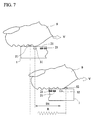
- FIG. 7 is a side view showing the sweep-type fingerprint sensor in operation according to the first embodiment of the invention. It is to be noted that the dimensions of the finger and sensor are not depicted in the real scale.
- the sweep-type fingerprint sensor module of the invention includes a microprocessor 11 and a sweep-type fingerprint sensor 10 electrically connected to the microprocessor 11.
- the sweep-type fingerprint sensor 10 includes a substrate 1, a sensing members array 2, a speed-detecting unit 3, a processing circuit 4, an impedance sensor 5, and a plurality of bonding pads 6.
- the bonding pads 6 are electrically connected to the microprocessor 11.
- the sensing members array 2 is formed on the substrate 1 and is composed of a plurality of fingerprint sensing members 21 arranged in a two-dimensional array. It is to be noted that only one sensing member is depicted in the drawing for the sake of simplicity.
- Each of the fingerprint sensing members 21 may be a capacitive sensing member, a capacitive pressure sensing member, or a thermoelectric sensing member, as described in the commonly-owned, co-pending patent applications:
- the lateral (X-axis direction) dimension of the sensing members array 2 is at least greater than 8 mm, and the Y-axis (longitudinal) direction can only leave the dimension of the single sensing member.
- the optimum longitudinal (Y-axis direction) dimension preferably ranges from 2.5 to 3.5 mm, which will be described later.
- the processing circuit 4 basically includes a logic control circuit, a programmable gain amplifier, and an analog-to-digital converter, the corresponding detailed architectures of which have been described in the patent applications of "CAPACITIVE FINGERPRINT SENSOR” and "CAPACITIVE PRESSURE FINGERPRINT SENSOR AND A METHOD FOR MANUFACTURING THE SAME.”
- the sensing members array 2 senses a fingerprint when a finger 9 (FIG. 3) sweeps across the sensing members array 2, sequentially acquires a plurality of fingerprint fragment images from the finger with a sampling time interval, and then outputs a plurality of fingerprint fragment signals corresponding to the fingerprint fragment images.
- the speed-detecting unit 3 is embedded in the sweep-type fingerprint sensor of the invention.
- the speed-detecting unit 3 is also formed on the substrate 1 and is composed of a first plate electrode 31 and a second plate electrode 32.
- the first and second plate electrodes 31 and 32 are substantially parallel to each other and are spaced apart by a predetermined distance D1.
- the plate electrodes are positioned at two sides (upper and lower sides) of the sensing members array 2, respectively, and each has a length substantially equal to the length of the sensing members array 2 in the X-axis direction.
- the first plate electrode 31 outputs a first time signal when it contacts the finger 9
- the second plate electrode 32 outputs a second time signal when it contacts the finger 9.
- the finger 9 when the finger 9 sweeps in the Y-axis direction, the finger 9 passes over the first plate electrode 31 to form a trigger capacitance together with the first plate electrode 31 (the corresponding detailed circuit and principle have been described in the patent application of "CAPACITIVE FINGERPRINT SENSOR"), and then a trigger pulse is generated.
- the trigger pulse may turn on the power of the fingerprint sensor so as to reduce unnecessary power consumption when the sensor is not used.
- the finger 9 sweeps across the surface the sensing members array 2 and passes over the second plate electrode 32, and another trigger pulse is also generated. Since the distance D1 between the first and second plate electrodes 31 and 32 is known, the sweeping speed V of the finger 9 may be derived after the time difference between the two trigger pulses is calculated. In this embodiment, the sweeping speed V is calculated by the microprocessor 11.
- the sampling time interval used to acquire the fingerprint fragment images may be calculated. Then, the fingerprint fragment images may be received and processed. Consequently, it is unnecessary to store too many fingerprint fragment images, the microprocessor needs not to have powerful processing speed, and the cost of the module may be advantageously reduced.
- the invention considers both the property and cost of the fingerprint sensor and optimizes the dimension of the sensing members array 2 in the Y-axis direction as ranging from 2.5 to 3.5 mm.
- the dimension W in the X-axis direction is 10 mm
- the dimension L in the Y-axis direction is 3.2 mm.
- the overlapped regions are illustrated as A(1) to A(N-1), as shown in FIG. 4.
- the invention may optimize the Y-axis dimension of the sensing members array 2 as ranging from 2.5 to 3.5 mm by way of sweeping speed detection of the finger, and the reconstructed image is shown in FIG. 4.
- the unoverlapped region of the image has a length ranging from 1.5 to 2.5 mm in the Y-axis direction.
- a complete image may be obtained by reconstructing 3 to 5 or 7 to 9 fragment images. Consequently, the required number of fingerprint fragment images may be greatly reduced, and the fragment images may be reorganized together according to the stable and commonly used method of minutia extraction and matching.
- the processing circuit 4 is electrically connected to the sensing members array 2 and the speed-detecting unit 3 to receive and process the plurality of fingerprint fragment signals, the first time signal, and the second time signal. Then, the processed signals are output to the microprocessor 11 via the bonding pads 6.
- the microprocessor 11 derives a sweeping speed V of the finger 9 according to the first time signal, the second time signal, and the predetermined distance D1, determines the sampling time interval according to the sweeping speed V, and further processes and reconstructs the plurality of fingerprint fragments into a complete fingerprint image.
- the embodiment of the invention also provides the live finger detection technology, wherein the impedance sensor 5 is formed on the substrate 1 to sense the impedance of the finger 9 skin to discriminate if the finger 9 is live or not.
- the impedance sensor 5 includes a pair of exposed metallic, long electrodes 51 and 52.
- the impedance R of the finger 9 skin may be detected and recorded in the microprocessor. Since the impedance of a fake finger or a dead finger is different from a true and live finger, the true/false condition of the finger may be recognized by the processing of the microprocessor 11.
- another embodiment of the live finger detection technology may utilize the thermal conductivity property of the finger's skin to determine whether or not the finger is alive.
- the main discrimination principle is based on that the live finger's skin contains sufficient water and has good thermal conductivity while the fake finger is usually made of silicone or other soft polymeric material with relatively poor thermal conductivity.
- a cut finger has a lower thermal conductance owing to the loss of blood.
- the method is implemented by disposing a thermoelectric sensor and a heating resistor on a predetermined area of the chip for sensing the temperature variation signal by the thermoelectric sensor when the finger's skin touches the sensor surface or not.
- the detection flow is: after the finger contacts the sensor surface and enables the power trigger switch, a pulse current or voltage is supplied to the heating resistor to raise the temperature of the predetermined area to, for example, 50 to 60 °C, which is higher than the finger's temperature. Then, the finger's skin contacts the predetermined area and takes some heat therefrom thus lower down the temperature.
- Counting the time interval from the raising of temperature to the peak temperature happening by the thermoelectric sensor can estimate the thermal conductivity characteristics of a live finger skin, wherein the skin's thermal conductance property cannot be easily changed even the ambient temperature variation and is a stable physical quantity. So, unlike the human body temperature detection, which tends to be interfered by the external environment and lose the judgement standard, this method is very suitable for the live finger detection.
- a more precise live finger detection method may further be constructed by combining the thermal conductivity and the temperature detection methods for composite judgement.
- any type of thermal sensor or temperature sensor also could be used to detect the temperature variation.
- FIG. 8 is a flow chart showing a sensing method for the sweep-type fingerprint sensor of the invention.
- the sensing method for the sweep-type fingerprint sensor of the invention includes the following steps.
- step S 10 a sweeping speed V of the finger 9 is detected.
- a first time signal is output.
- a second time signal is output.
- the sweeping speed V may be obtained by dividing the predetermined distance D1 by the time difference between the first and second time signals.
- a sampling time interval is determined according to the sweeping speed V.
- an effective length is obtained by subtracting an overlapped length (determined by the fingerprint image processing software) between two adjacent fingerprint fragment images from an image length (Y-axis length of the sensing members array) of each fingerprint fragment image in a sweeping direction of the finger. Then, the sampling time interval is obtained by dividing the effective length by the sweeping speed.
- step S30 a plurality of fingerprint fragment images of the finger 9 is sequentially acquired with the sampling time interval. Then, a plurality of fingerprint fragment signals corresponding to the fingerprint fragment images is output accordingly.
- step S40 the plurality of fingerprint fragment signals is reconstructed into a complete fingerprint image.
- step S50 whether the finger is live or not is determined by the impedance detection or the thermal conductivity estimation method.
- the invention detects the sweeping speed of the finger to determine the sampling time interval for the fingerprint fragment images so as to effectively reduce the number of fingerprint fragment images, simplify the image processing, and reduce the sensor cost.
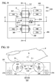
- FIG. 9 is a schematic top view showing a sweep-type fingerprint sensor module according to a second embodiment of the invention.
- FIG. 10 is a schematically cross-sectional view taken along a line 10-10 of FIG. 9.
- the sweep-type fingerprint sensor module 201 of this embodiment includes a sweep-type fingerprint sensor 210, a T/G (transmission and guiding) mechanism 220, a panel 240, two micro switches 250, two speed/displacement sensors 260, and two drive mechanisms 270.
- the sweep-type fingerprint sensor 210 has a rectangular sensing surface 211 for sensing a plurality of fingerprint fragment images of a finger F sweeping in a direction A. The fingerprint fragment images are transferred to a microprocessor (not shown) for image reconstruction.
- the T/G mechanism 220 for guiding the finger F in a stably sweeping direction across the sensing surface 211 is disposed beside the sweep-type fingerprint sensor 210 and is driven along a guiding direction corresponding to the sweeping direction A.
- the T/G mechanism 220 includes two rollers 221 and 222, and the sweep-type fingerprint sensor 210 is positioned between the two rollers 221 and 222.
- the sweep-type fingerprint sensor 210 and the T/G mechanism 220 composed of the rollers 221 and 222 are arranged in one straight line L1 along the sweep direction A. That is, the guiding direction of the T/G mechanism 220 is perpendicular to a long edge 211A of the rectangular sensing surface 211 of the sweep-type fingerprint sensor 210.
- the roller 221 is located in front of the sweep-type fingerprint sensor 210 or at a side of the long edge 211A of the rectangular sensing surface 211 such that a specific portion F1 of the finger F may firstly move across the roller 221 and then the sensing surface 211.
- the roller 222 is located in back of the sweep-type fingerprint sensor 210 or at the other side of the long edge 211A of the rectangular sensing surface 211 such that the specific portion F1 of the finger F may firstly move across the sensing surface 211 and then the roller 222. In fact, only one of the rollers 221 and 222 may achieve the effect of the invention.
- the finger F will follow the rolling inertia of the roller when sweeping across the sensor surface and ensure the sweeping behavior in an almost straight direction to avoid unclear image reconstruction due to finger shaking and so on. So, the jitters in the left and right directions perpendicular to the sweep direction A when the finger F sweeps across may be effectively eliminated.
- the T/G mechanism may be a caterpillar T/G mechanism that is similar to the sheet-feeding mechanism of a copier, wherein the caterpillar cooperates with the finger to achieve the effect of the invention.
- the micro switch 250 is an optional member to be in contact with the rollers 221 and 222 of the T/G mechanism 220.
- the micro switch 250 may be triggered and thus turn on the power of the sweep-type fingerprint sensor 210.
- the main power of the fingerprint sensor 210 need not to be always turned on. Instead, the main power may be turned on by the pressing of the finger F on the rollers 221 and 222 of the T/G mechanism 220 to trigger the micro switch 250 when needed.
- the speed/displacement sensor 260 is also an optional member for sensing a rotating speed or a displacement of the T/G mechanism 220, and then outputting a rotating speed signal or a displacement signal S1 to the microprocessor (not shown), such that the microprocessor determines the minimum number of the to-be-acquired fingerprint fragment images and thus a plurality of fingerprint fragment images is acquired according to the rotating speed signal or the displacement signal S1.
- the direction of the speed/displacement may be determined in the opto-electronic manner, the electric manner, the magnetic force manner, and the like, which are to be described later.
- the sensing time interval between two adjacent fingerprint fragment images may be optimized when the rotating speed of the T/G mechanism 220 is already known, and the subsequent image reconstruction procedure may be facilitated.
- the drive mechanism 270 such as a motor is also an optional member for driving the T/G mechanism 220 to rotate so as to drive the finger F to sweep across the sensing surface 211.
- the driving speed of the drive mechanism 270 is known, and the sensing time interval between two adjacent fingerprint fragment images also may be optimized without worrying about the slight fluctuations of the sweeping speed of the user's finger during this period of time.
- the finger's sweep direction may also be fixed.
- the panel 240 is a flat panel, and the sweep-type fingerprint sensor 210 and the T/G mechanism 220 are disposed on the panel 240.
- the width of the T/G mechanism 220 may be greater than, smaller than or equal to that of the fingerprint sensor 210.
- Each of the rollers 221 and 222 has an exposed portion exposed from each of the openings 242 and 243 (as indicated by the rectangles defined by the solid lines) of the panel 240 so as to contact the finger while rotating about the shafts 223 and 224.
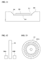
- FIG. 11 is a schematically cross-sectional view showing a modified embodiment taken along a line 11-11 of FIG. 9.
- the panel 240 has a U-shaped groove 241, in which the sweep-type fingerprint sensor 210 and the T/G mechanism 220 are disposed.
- the T/G mechanism 220 may be flush with or higher than the sweep-type fingerprint sensor 210.
- FIG. 12 is a side view showing the roller and speed/position detector of FIG. 10.
- FIG. 13 is front view showing the roller of FIG. 10. It is to be noted that the difference between the speed and displacement detections is only in that the speed detection takes the time into account, while the displacement detection does not.
- the emitter 260A of the speed/position detector 260 continuously emits a signal (such as an infrared signal). Because the signal can only pass through the opening 221A of the roller 221, the receiver 260B discontinuously receives this emitted signal, which discontinuously penetrates through the openings 221A of the roller 221, so as to generate several pulses as the displacement signal. By calculating the pulse number per unit time, the roller's rotation speed, which may correspond to the finger's sweeping speed, may be obtained.
- the sweep-type fingerprint sensor module may be configured such that the fingerprint sensor starts to acquires one fingerprint fragment image each time when the receiver 260B receives one pulse.
- Such a design may be easily accomplished according to the rotating angle of the roller 221 and the finger's sweeping displacement corresponding to the arc length between two adjacent openings 221A of the roller 221. In this condition, even if the finger's sweeping speed fluctuation is larger, the acquiring of the fingerprint fragment images also cannot be influenced.
- the width (the length in the direction A) of the fingerprint sensor is known, the displacement corresponding to the rotating roller's opening 221A may be configured such that the sensor acquires one fragment fingerprint image each time when the pulse signal appears. In this way, the sweeping speed need not to be detected.
- the transmittive speed/position detector 260 mentioned in the example also may be replaced by a reflective speed/position detector.
- the emitter 260A and receiver 260B are located at the same side of the roller 221.
- Forming patterns, which correspond to the openings 221A, on the surface of the roller 221 may enable the receiver 260B to receive the emitted signal reflected by the roller 221 so as to generate several pulses as the displacement signal.
- the jitters generated when the finger sweeps across the sensor may be effectively avoided, the fingerprint sensor also may be powered according to the provided switch function, and the finger's sweeping speed or sweeping distance also may be detected to serve as the basis for sensing the finger's fingerprint fragment images.
Landscapes
- Engineering & Computer Science (AREA)
- Human Computer Interaction (AREA)
- Physics & Mathematics (AREA)
- General Physics & Mathematics (AREA)
- Multimedia (AREA)
- Theoretical Computer Science (AREA)
- Image Input (AREA)
- Measurement Of The Respiration, Hearing Ability, Form, And Blood Characteristics Of Living Organisms (AREA)
Applications Claiming Priority (2)
| Application Number | Priority Date | Filing Date | Title |
|---|---|---|---|
| US441022 | 2003-05-20 | ||
| US10/441,022 US7200250B2 (en) | 2003-05-20 | 2003-05-20 | Sweep-type fingerprint sensor module |
Publications (2)
| Publication Number | Publication Date |
|---|---|
| EP1482441A2 true EP1482441A2 (de) | 2004-12-01 |
| EP1482441A3 EP1482441A3 (de) | 2005-02-09 |
Family
ID=33131520
Family Applications (1)
| Application Number | Title | Priority Date | Filing Date |
|---|---|---|---|
| EP04010331A Withdrawn EP1482441A3 (de) | 2003-05-20 | 2004-04-30 | Streifensensormodul und zugehöriges Aufnahmeverfahren |
Country Status (3)
| Country | Link |
|---|---|
| US (1) | US7200250B2 (de) |
| EP (1) | EP1482441A3 (de) |
| CN (1) | CN1551037A (de) |
Cited By (1)
| Publication number | Priority date | Publication date | Assignee | Title |
|---|---|---|---|---|
| EP1873686A3 (de) * | 2006-06-26 | 2012-03-21 | Hitachi-Omron Terminal Solutions, Corp. | Biometrische Vorrichtung |
Families Citing this family (90)
| Publication number | Priority date | Publication date | Assignee | Title |
|---|---|---|---|---|
| FR2849246B1 (fr) * | 2002-12-20 | 2006-03-10 | Sagem | Procede de determination du caractere vivant d'un element porteur d'une empreinte digitale |
| DE60327664D1 (de) * | 2003-08-13 | 2009-06-25 | Hitachi Ltd | Persönliche identifikationseinrichtung |
| US7706581B2 (en) * | 2003-09-11 | 2010-04-27 | Nxp B.V. | Fingerprint detection using sweep-type imager with optoelectronic speed sensor |
| JP4387764B2 (ja) * | 2003-11-10 | 2009-12-24 | 富士通株式会社 | 認証装置および認証システム |
| JP4462988B2 (ja) * | 2004-04-13 | 2010-05-12 | Necインフロンティア株式会社 | 指紋読取方法および指紋読取システム |
| US8447077B2 (en) | 2006-09-11 | 2013-05-21 | Validity Sensors, Inc. | Method and apparatus for fingerprint motion tracking using an in-line array |
| US8229184B2 (en) * | 2004-04-16 | 2012-07-24 | Validity Sensors, Inc. | Method and algorithm for accurate finger motion tracking |
| US8358815B2 (en) * | 2004-04-16 | 2013-01-22 | Validity Sensors, Inc. | Method and apparatus for two-dimensional finger motion tracking and control |
| US8165355B2 (en) * | 2006-09-11 | 2012-04-24 | Validity Sensors, Inc. | Method and apparatus for fingerprint motion tracking using an in-line array for use in navigation applications |
| US8077935B2 (en) * | 2004-04-23 | 2011-12-13 | Validity Sensors, Inc. | Methods and apparatus for acquiring a swiped fingerprint image |
| US8131026B2 (en) | 2004-04-16 | 2012-03-06 | Validity Sensors, Inc. | Method and apparatus for fingerprint image reconstruction |
| US8175345B2 (en) | 2004-04-16 | 2012-05-08 | Validity Sensors, Inc. | Unitized ergonomic two-dimensional fingerprint motion tracking device and method |
| US20060078178A1 (en) * | 2004-09-18 | 2006-04-13 | Will Shatford | Swipe sensor |
| JP4339221B2 (ja) * | 2004-09-30 | 2009-10-07 | Necインフロンティア株式会社 | 画像構成方法、指紋画像構成装置およびプログラム |
| WO2006041780A1 (en) * | 2004-10-04 | 2006-04-20 | Validity Sensors, Inc. | Fingerprint sensing assemblies comprising a substrate |
| JP2006230603A (ja) * | 2005-02-23 | 2006-09-07 | Canon Inc | 撮像装置、生体認証システム及び画像取得方法 |
| JP2006260054A (ja) * | 2005-03-16 | 2006-09-28 | Sharp Corp | 認証装置、認証方法、認証方法をコンピュータに実行させるための認証プログラムおよび当該プログラムを記録した機械読取り可能な記録媒体 |
| TWI303388B (en) * | 2005-03-18 | 2008-11-21 | Egis Technology Inc | A sweep-type image sensing chip with image matching function and processing method therefor |
| CN1332346C (zh) * | 2005-05-26 | 2007-08-15 | 上海交通大学 | 扩展相位相关的滑动指纹序列无缝拼接方法 |
| CN100524339C (zh) * | 2005-07-18 | 2009-08-05 | 神盾股份有限公司 | 具有图像比较功能的滑动式影像感测芯片及其处理方法 |
| JP4757071B2 (ja) * | 2006-03-27 | 2011-08-24 | 富士通株式会社 | 指紋認証装置および情報処理装置 |
| CN101079087B (zh) * | 2006-05-26 | 2010-05-12 | 神盾股份有限公司 | 具有滑动式指纹感测芯片的计算机无线外围设备 |
| US8107212B2 (en) * | 2007-04-30 | 2012-01-31 | Validity Sensors, Inc. | Apparatus and method for protecting fingerprint sensing circuitry from electrostatic discharge |
| US20110002461A1 (en) * | 2007-05-11 | 2011-01-06 | Validity Sensors, Inc. | Method and System for Electronically Securing an Electronic Biometric Device Using Physically Unclonable Functions |
| US8290150B2 (en) | 2007-05-11 | 2012-10-16 | Validity Sensors, Inc. | Method and system for electronically securing an electronic device using physically unclonable functions |
| US8276816B2 (en) | 2007-12-14 | 2012-10-02 | Validity Sensors, Inc. | Smart card system with ergonomic fingerprint sensor and method of using |
| US8204281B2 (en) * | 2007-12-14 | 2012-06-19 | Validity Sensors, Inc. | System and method to remove artifacts from fingerprint sensor scans |
| US8005276B2 (en) * | 2008-04-04 | 2011-08-23 | Validity Sensors, Inc. | Apparatus and method for reducing parasitic capacitive coupling and noise in fingerprint sensing circuits |
| US8116540B2 (en) | 2008-04-04 | 2012-02-14 | Validity Sensors, Inc. | Apparatus and method for reducing noise in fingerprint sensing circuits |
| GB2474999B (en) | 2008-07-22 | 2013-02-20 | Validity Sensors Inc | System and method for securing a device component |
| US8391568B2 (en) | 2008-11-10 | 2013-03-05 | Validity Sensors, Inc. | System and method for improved scanning of fingerprint edges |
| US8600122B2 (en) | 2009-01-15 | 2013-12-03 | Validity Sensors, Inc. | Apparatus and method for culling substantially redundant data in fingerprint sensing circuits |
| US8278946B2 (en) * | 2009-01-15 | 2012-10-02 | Validity Sensors, Inc. | Apparatus and method for detecting finger activity on a fingerprint sensor |
| US8374407B2 (en) | 2009-01-28 | 2013-02-12 | Validity Sensors, Inc. | Live finger detection |
| US8605960B2 (en) * | 2009-03-02 | 2013-12-10 | Avago Technologies General Ip (Singapore) Pte. Ltd. | Fingerprint sensing device |
| TW201044284A (en) * | 2009-06-09 | 2010-12-16 | Egis Technology Inc | Image sensing device adapted to flat surface design |
| US8331775B2 (en) * | 2009-10-15 | 2012-12-11 | Jack Harper | Fingerprint scanning systems and methods |
| US9274553B2 (en) | 2009-10-30 | 2016-03-01 | Synaptics Incorporated | Fingerprint sensor and integratable electronic display |
| US9400911B2 (en) | 2009-10-30 | 2016-07-26 | Synaptics Incorporated | Fingerprint sensor and integratable electronic display |
| US9336428B2 (en) | 2009-10-30 | 2016-05-10 | Synaptics Incorporated | Integrated fingerprint sensor and display |
| US8421890B2 (en) | 2010-01-15 | 2013-04-16 | Picofield Technologies, Inc. | Electronic imager using an impedance sensor grid array and method of making |
| US8866347B2 (en) | 2010-01-15 | 2014-10-21 | Idex Asa | Biometric image sensing |
| US8791792B2 (en) | 2010-01-15 | 2014-07-29 | Idex Asa | Electronic imager using an impedance sensor grid array mounted on or about a switch and method of making |
| US9666635B2 (en) | 2010-02-19 | 2017-05-30 | Synaptics Incorporated | Fingerprint sensing circuit |
| US8716613B2 (en) * | 2010-03-02 | 2014-05-06 | Synaptics Incoporated | Apparatus and method for electrostatic discharge protection |
| US10430871B2 (en) * | 2010-05-21 | 2019-10-01 | Ncr Corporation | Self-service terminal |
| US9001040B2 (en) | 2010-06-02 | 2015-04-07 | Synaptics Incorporated | Integrated fingerprint sensor and navigation device |
| US8331096B2 (en) | 2010-08-20 | 2012-12-11 | Validity Sensors, Inc. | Fingerprint acquisition expansion card apparatus |
| US8594393B2 (en) | 2011-01-26 | 2013-11-26 | Validity Sensors | System for and method of image reconstruction with dual line scanner using line counts |
| US8538097B2 (en) | 2011-01-26 | 2013-09-17 | Validity Sensors, Inc. | User input utilizing dual line scanner apparatus and method |
| US9406580B2 (en) | 2011-03-16 | 2016-08-02 | Synaptics Incorporated | Packaging for fingerprint sensors and methods of manufacture |
| US10043052B2 (en) | 2011-10-27 | 2018-08-07 | Synaptics Incorporated | Electronic device packages and methods |
| US9195877B2 (en) | 2011-12-23 | 2015-11-24 | Synaptics Incorporated | Methods and devices for capacitive image sensing |
| US9785299B2 (en) | 2012-01-03 | 2017-10-10 | Synaptics Incorporated | Structures and manufacturing methods for glass covered electronic devices |
| US9137438B2 (en) | 2012-03-27 | 2015-09-15 | Synaptics Incorporated | Biometric object sensor and method |
| US9251329B2 (en) | 2012-03-27 | 2016-02-02 | Synaptics Incorporated | Button depress wakeup and wakeup strategy |
| US9268991B2 (en) | 2012-03-27 | 2016-02-23 | Synaptics Incorporated | Method of and system for enrolling and matching biometric data |
| US9600709B2 (en) | 2012-03-28 | 2017-03-21 | Synaptics Incorporated | Methods and systems for enrolling biometric data |
| US9152838B2 (en) | 2012-03-29 | 2015-10-06 | Synaptics Incorporated | Fingerprint sensor packagings and methods |
| EP2836960B1 (de) | 2012-04-10 | 2018-09-26 | Idex Asa | Biometrische erfassung |
| US9244576B1 (en) | 2012-12-21 | 2016-01-26 | Cypress Semiconductor Corporation | User interface with child-lock feature |
| CN103914694A (zh) * | 2013-01-04 | 2014-07-09 | 贝伦企业股份有限公司 | 侦测模块、指纹感测装置及指纹影像产生方法 |
| US9665762B2 (en) * | 2013-01-11 | 2017-05-30 | Synaptics Incorporated | Tiered wakeup strategy |
| NO20140653A1 (no) | 2014-05-27 | 2015-11-30 | Idex Asa | Biometrisk sensor |
| CN105528598B (zh) * | 2014-09-29 | 2019-03-29 | 上海箩箕技术有限公司 | 光学指纹传感器 |
| USD776664S1 (en) * | 2015-05-20 | 2017-01-17 | Chaya Coleena Hendrick | Smart card |
| KR20170025083A (ko) * | 2015-08-27 | 2017-03-08 | 삼성전기주식회사 | 지문 감지 장치 및 이를 포함하는 전자 장치 |
| CN107025041B (zh) * | 2016-01-29 | 2020-11-10 | 北京小米移动软件有限公司 | 指纹录入方法及终端 |
| CN108957178A (zh) * | 2016-03-25 | 2018-12-07 | 江苏凯尔生物识别科技有限公司 | 用于生物识别模组的多压力可调测试装置 |
| GB2552131A (en) * | 2016-05-06 | 2018-01-17 | Zwipe As | Electrical validation of a purported finger |
| CN106127132B (zh) * | 2016-06-20 | 2019-07-16 | 北京小米移动软件有限公司 | 滑动式录入指纹的提示方法及装置、电子设备 |
| US10460144B2 (en) | 2016-07-20 | 2019-10-29 | Cypress Semiconductor Corporation | Non-finger object rejection for fingerprint sensors |
| US10599911B2 (en) * | 2016-07-20 | 2020-03-24 | Cypress Semiconductor Corporation | Anti-spoofing protection for fingerprint controllers |
| CN106250882A (zh) * | 2016-08-26 | 2016-12-21 | 广东欧珀移动通信有限公司 | 指纹识别感测装置、电子设备和移动终端 |
| CN107958174A (zh) * | 2016-11-01 | 2018-04-24 | 深圳信炜科技有限公司 | 生物识别模组和移动终端 |
| CN108304085B (zh) * | 2017-01-11 | 2021-01-01 | 神盾股份有限公司 | 判断手指位移方向的方法和电子装置 |
| EP3679519B1 (de) * | 2017-09-07 | 2024-11-06 | Fingerprint Cards Anacatum IP AB | Verfahren und fingerabdruckerfassungssystem zur bestimmung des fingerkontakts mit einem fingerabdrucksensor |
| TWI651626B (zh) * | 2017-11-30 | 2019-02-21 | 大陸商北京集創北方科技股份有限公司 | 生物特徵資料加密方法及利用其之資訊處理裝置 |
| CN108073912B (zh) * | 2018-01-03 | 2021-01-26 | 京东方科技集团股份有限公司 | 指纹识别装置和指纹识别设备 |
| CN108209897A (zh) * | 2018-01-30 | 2018-06-29 | 四川东鼎里智信息技术有限责任公司 | 一种可穿戴产品的移动医疗助理系统 |
| CN108254107A (zh) * | 2018-02-08 | 2018-07-06 | 四川东鼎里智信息技术有限责任公司 | 一种石墨烯压力传感系统 |
| CN108363488A (zh) * | 2018-02-08 | 2018-08-03 | 四川东鼎里智信息技术有限责任公司 | 一种可穿戴全息传送系统 |
| CN108294740A (zh) * | 2018-02-08 | 2018-07-20 | 四川东鼎里智信息技术有限责任公司 | 一种石墨烯心率传感系统 |
| TWI652625B (zh) * | 2018-03-16 | 2019-03-01 | 友達光電股份有限公司 | 指紋感測裝置 |
| KR102156357B1 (ko) * | 2018-12-17 | 2020-09-15 | 연세대학교 산학협력단 | 스와이프 라인 촬상 센서를 이용하여 등간격 이미지를 취득하는 이미지 취득 시스템 및 방법, 그것을 포함하는 지문인증시스템 및 컨트롤러시스템 |
| CN109359638B (zh) * | 2018-12-18 | 2021-05-07 | 厦门天马微电子有限公司 | 滑动指纹识别方法、阵列基板、显示面板及显示装置 |
| US11106887B1 (en) * | 2020-05-07 | 2021-08-31 | Novatek Microelectronics Corp. | Electronic circuit and a method for generating a fingerprint image |
| TWI766474B (zh) * | 2020-06-15 | 2022-06-01 | 神盾股份有限公司 | 指紋感測裝置以及指紋感測方法 |
| TWI816397B (zh) * | 2021-12-30 | 2023-09-21 | 仟融科技股份有限公司 | 膚紋控制系統、膚紋控制方法、膚紋取樣裝置及電腦可讀媒體 |
| CN114495328B (zh) * | 2022-01-19 | 2024-02-20 | 深圳市凯迪仕智能科技股份有限公司 | 一种门锁装置及其控制方法 |
Family Cites Families (15)
| Publication number | Priority date | Publication date | Assignee | Title |
|---|---|---|---|---|
| FR2749955B1 (fr) * | 1996-06-14 | 1998-09-11 | Thomson Csf | Systeme de lecture d'empreintes digitales |
| NO304766B1 (no) | 1997-06-16 | 1999-02-08 | Sintef | Fingeravtrykksensor |
| GB9725571D0 (en) * | 1997-12-04 | 1998-02-04 | Philips Electronics Nv | Electronic apparatus comprising fingerprint sensing devices |
| US6643389B1 (en) | 2000-03-28 | 2003-11-04 | Stmicroelectronics, Inc. | Narrow array capacitive fingerprint imager |
| NO314647B1 (no) | 2000-06-09 | 2003-04-22 | Idex Asa | Målesystem for fingeravtrykksensor |
| JP3559754B2 (ja) * | 2000-07-25 | 2004-09-02 | Necエレクトロニクス株式会社 | 指紋認証装置 |
| WO2002061668A1 (en) | 2000-12-05 | 2002-08-08 | Arete Associates, A California Corporation | Linear contact sensor apparatus and method for use in imaging features of an object |
| DE60114241T2 (de) * | 2000-12-05 | 2006-07-13 | Validity Sensors Inc., Phoenix | System und methode zur kapazitiven aufnahme von fingerabdrücken durch überstreichen |
| DE10109560B4 (de) | 2001-02-28 | 2007-02-08 | Infineon Technologies Ag | Lesevorrichtung für Fingerabdrücke |
| DE60215810T2 (de) * | 2001-06-27 | 2007-09-06 | Activcard Ireland Ltd. | Verfahren und gerät zur transformation eines bildes einer biologischen oberfläche |
| US7113622B2 (en) * | 2001-06-27 | 2006-09-26 | Laurence Hamid | Swipe imager with improved sensing control features |
| US7203347B2 (en) * | 2001-06-27 | 2007-04-10 | Activcard Ireland Limited | Method and system for extracting an area of interest from within a swipe image of a biological surface |
| US7043061B2 (en) * | 2001-06-27 | 2006-05-09 | Laurence Hamid | Swipe imager with multiple sensing arrays |
| US20030115490A1 (en) * | 2001-07-12 | 2003-06-19 | Russo Anthony P. | Secure network and networked devices using biometrics |
| CN1235172C (zh) * | 2002-02-20 | 2006-01-04 | 佳能株式会社 | 图像输入装置 |
-
2003
- 2003-05-20 US US10/441,022 patent/US7200250B2/en not_active Expired - Lifetime
-
2004
- 2004-04-30 EP EP04010331A patent/EP1482441A3/de not_active Withdrawn
- 2004-05-14 CN CNA2004100383024A patent/CN1551037A/zh active Pending
Cited By (1)
| Publication number | Priority date | Publication date | Assignee | Title |
|---|---|---|---|---|
| EP1873686A3 (de) * | 2006-06-26 | 2012-03-21 | Hitachi-Omron Terminal Solutions, Corp. | Biometrische Vorrichtung |
Also Published As
| Publication number | Publication date |
|---|---|
| CN1551037A (zh) | 2004-12-01 |
| US7200250B2 (en) | 2007-04-03 |
| EP1482441A3 (de) | 2005-02-09 |
| US20040234110A1 (en) | 2004-11-25 |
Similar Documents
| Publication | Publication Date | Title |
|---|---|---|
| EP1482441A2 (de) | Streifensensormodul und zugehöriges Aufnahmeverfahren | |
| US20050111708A1 (en) | Sweep-type fingerprint sensor device capable of guiding a finger in a fixed sweeping direction | |
| US6643389B1 (en) | Narrow array capacitive fingerprint imager | |
| US8073204B2 (en) | Hybrid multi-sensor biometric identification device | |
| US10776605B2 (en) | Multifunction fingerprint sensor | |
| CN1119766C (zh) | 指纹读取系统 | |
| US6333989B1 (en) | Contact imaging device | |
| US8605960B2 (en) | Fingerprint sensing device | |
| US9721137B2 (en) | Method and apparatus for fingerprint image reconstruction | |
| US7113622B2 (en) | Swipe imager with improved sensing control features | |
| US4394773A (en) | Fingerprint sensor | |
| EP3218849B1 (de) | Fingerabdrucksensoren mit pixelinternen optischen sensoren | |
| US5963679A (en) | Electric field fingerprint sensor apparatus and related methods | |
| US8358815B2 (en) | Method and apparatus for two-dimensional finger motion tracking and control | |
| EP0929050A2 (de) | Abtastfähiger Halbleiterfingerabdrukdetektor | |
| US6628377B1 (en) | Scanning optical semiconductor fingerprint detector | |
| EP1207786A2 (de) | Piezoelektrischer dünnschichtfingerabdruckabtaster | |
| Memon et al. | Review of finger print sensing technologies | |
| GB2424304A (en) | Generating non-overlapping partial fingerprints with a sweep sensor | |
| JP2004348726A (ja) | スウィープ式指紋センサモジュール及びその検出方法 | |
| KR20220062646A (ko) | 존재 센서를 갖는 생체 인식 센서 | |
| JP2003150943A (ja) | 画像読み取り装置 | |
| Bilinsky et al. | Fingerprint scanners | |
| KR20070094099A (ko) | 영상 매칭 기능을 갖는 선형 영상 감지 장치 및 그를 위한처리방법 | |
| KR20080045094A (ko) | 영상 매칭 기능을 갖는 선형 영상 감지 장치 및 그를 위한처리방법 |
Legal Events
| Date | Code | Title | Description |
|---|---|---|---|
| PUAI | Public reference made under article 153(3) epc to a published international application that has entered the european phase |
Free format text: ORIGINAL CODE: 0009012 |
|
| AK | Designated contracting states |
Kind code of ref document: A2 Designated state(s): AT BE BG CH CY CZ DE DK EE ES FI FR GB GR HU IE IT LI LU MC NL PL PT RO SE SI SK TR |
|
| AX | Request for extension of the european patent |
Extension state: AL HR LT LV MK |
|
| PUAL | Search report despatched |
Free format text: ORIGINAL CODE: 0009013 |
|
| AK | Designated contracting states |
Kind code of ref document: A3 Designated state(s): AT BE BG CH CY CZ DE DK EE ES FI FR GB GR HU IE IT LI LU MC NL PL PT RO SE SI SK TR |
|
| AX | Request for extension of the european patent |
Extension state: AL HR LT LV MK |
|
| AKX | Designation fees paid | ||
| REG | Reference to a national code |
Ref country code: DE Ref legal event code: 8566 |
|
| STAA | Information on the status of an ep patent application or granted ep patent |
Free format text: STATUS: THE APPLICATION IS DEEMED TO BE WITHDRAWN |
|
| 18D | Application deemed to be withdrawn |
Effective date: 20050810 |