EP1482609A1 - Méthode de contrôle de la sortie spectrale d'un laser à l'effet Raman à multiple longueur d'onde - Google Patents
Méthode de contrôle de la sortie spectrale d'un laser à l'effet Raman à multiple longueur d'onde Download PDFInfo
- Publication number
- EP1482609A1 EP1482609A1 EP03291296A EP03291296A EP1482609A1 EP 1482609 A1 EP1482609 A1 EP 1482609A1 EP 03291296 A EP03291296 A EP 03291296A EP 03291296 A EP03291296 A EP 03291296A EP 1482609 A1 EP1482609 A1 EP 1482609A1
- Authority
- EP
- European Patent Office
- Prior art keywords
- output
- wavelength
- wavelengths
- adjusting
- relative
- Prior art date
- Legal status (The legal status is an assumption and is not a legal conclusion. Google has not performed a legal analysis and makes no representation as to the accuracy of the status listed.)
- Granted
Links
- 238000001069 Raman spectroscopy Methods 0.000 title claims abstract description 63
- 238000000034 method Methods 0.000 title claims abstract description 34
- 238000001228 spectrum Methods 0.000 title description 30
- 238000002310 reflectometry Methods 0.000 claims description 30
- 230000008569 process Effects 0.000 claims description 4
- 239000000835 fiber Substances 0.000 description 37
- 238000009826 distribution Methods 0.000 description 13
- 230000000694 effects Effects 0.000 description 13
- 230000003993 interaction Effects 0.000 description 6
- 230000008901 benefit Effects 0.000 description 5
- 230000003287 optical effect Effects 0.000 description 5
- 239000013307 optical fiber Substances 0.000 description 5
- 238000012546 transfer Methods 0.000 description 4
- 230000003321 amplification Effects 0.000 description 3
- 238000003199 nucleic acid amplification method Methods 0.000 description 3
- VYPSYNLAJGMNEJ-UHFFFAOYSA-N Silicium dioxide Chemical compound O=[Si]=O VYPSYNLAJGMNEJ-UHFFFAOYSA-N 0.000 description 2
- 238000013459 approach Methods 0.000 description 2
- 230000005540 biological transmission Effects 0.000 description 2
- 230000001419 dependent effect Effects 0.000 description 2
- 238000005086 pumping Methods 0.000 description 2
- 239000007787 solid Substances 0.000 description 2
- 230000008859 change Effects 0.000 description 1
- 238000004891 communication Methods 0.000 description 1
- 230000007423 decrease Effects 0.000 description 1
- 230000005284 excitation Effects 0.000 description 1
- 238000007429 general method Methods 0.000 description 1
- 230000001939 inductive effect Effects 0.000 description 1
- 238000002955 isolation Methods 0.000 description 1
- 230000007246 mechanism Effects 0.000 description 1
- 230000000737 periodic effect Effects 0.000 description 1
- 230000001902 propagating effect Effects 0.000 description 1
- 230000005855 radiation Effects 0.000 description 1
- 239000000377 silicon dioxide Substances 0.000 description 1
- 230000001629 suppression Effects 0.000 description 1
- 238000001845 vibrational spectrum Methods 0.000 description 1
Images


Classifications
-
- H—ELECTRICITY
- H01—ELECTRIC ELEMENTS
- H01S—DEVICES USING THE PROCESS OF LIGHT AMPLIFICATION BY STIMULATED EMISSION OF RADIATION [LASER] TO AMPLIFY OR GENERATE LIGHT; DEVICES USING STIMULATED EMISSION OF ELECTROMAGNETIC RADIATION IN WAVE RANGES OTHER THAN OPTICAL
- H01S3/00—Lasers, i.e. devices using stimulated emission of electromagnetic radiation in the infrared, visible or ultraviolet wave range
- H01S3/30—Lasers, i.e. devices using stimulated emission of electromagnetic radiation in the infrared, visible or ultraviolet wave range using scattering effects, e.g. stimulated Brillouin or Raman effects
- H01S3/302—Lasers, i.e. devices using stimulated emission of electromagnetic radiation in the infrared, visible or ultraviolet wave range using scattering effects, e.g. stimulated Brillouin or Raman effects in an optical fibre
-
- H—ELECTRICITY
- H01—ELECTRIC ELEMENTS
- H01S—DEVICES USING THE PROCESS OF LIGHT AMPLIFICATION BY STIMULATED EMISSION OF RADIATION [LASER] TO AMPLIFY OR GENERATE LIGHT; DEVICES USING STIMULATED EMISSION OF ELECTROMAGNETIC RADIATION IN WAVE RANGES OTHER THAN OPTICAL
- H01S3/00—Lasers, i.e. devices using stimulated emission of electromagnetic radiation in the infrared, visible or ultraviolet wave range
- H01S3/05—Construction or shape of optical resonators; Accommodation of active medium therein; Shape of active medium
- H01S3/06—Construction or shape of active medium
- H01S3/063—Waveguide lasers, i.e. whereby the dimensions of the waveguide are of the order of the light wavelength
- H01S3/067—Fibre lasers
- H01S3/0675—Resonators including a grating structure, e.g. distributed Bragg reflectors [DBR] or distributed feedback [DFB] fibre lasers
-
- H—ELECTRICITY
- H01—ELECTRIC ELEMENTS
- H01S—DEVICES USING THE PROCESS OF LIGHT AMPLIFICATION BY STIMULATED EMISSION OF RADIATION [LASER] TO AMPLIFY OR GENERATE LIGHT; DEVICES USING STIMULATED EMISSION OF ELECTROMAGNETIC RADIATION IN WAVE RANGES OTHER THAN OPTICAL
- H01S2301/00—Functional characteristics
- H01S2301/04—Gain spectral shaping, flattening
-
- H—ELECTRICITY
- H01—ELECTRIC ELEMENTS
- H01S—DEVICES USING THE PROCESS OF LIGHT AMPLIFICATION BY STIMULATED EMISSION OF RADIATION [LASER] TO AMPLIFY OR GENERATE LIGHT; DEVICES USING STIMULATED EMISSION OF ELECTROMAGNETIC RADIATION IN WAVE RANGES OTHER THAN OPTICAL
- H01S3/00—Lasers, i.e. devices using stimulated emission of electromagnetic radiation in the infrared, visible or ultraviolet wave range
- H01S3/05—Construction or shape of optical resonators; Accommodation of active medium therein; Shape of active medium
- H01S3/08—Construction or shape of optical resonators or components thereof
- H01S3/08086—Multiple-wavelength emission
Definitions
- the present invention relates to a method for adjusting the relative output power of individual output wavelengths of a multi-output-wavelength Raman laser. Further, the present invention relates to a device that performs such a method, i.e. a device for adjusting the relative output power of individual output wavelengths of such a laser.
- Multi-output-wavelength Raman lasers are per se known. These devices utilize the Raman effect for generating Laser output wavelengths in a wavelength range suitable for the amplification of communication signals propagating in optical fibers. As is well known, the Raman effect relies on interaction of light with matter. Raman interaction is an inelastic scattering process in which incident pumplight is downshifted in frequency, thereby downshifted in photon energy by a certain amount that corresponds to excitation energies of certain vibrational modes of the matter. The light that has been downshifted in frequency is usually called Stokes light or simply Stokes.
- the frequency of the scattered light may vary continuously as a function of a continuous vibrational spectrum of the solid state matter.
- the resulting broad and continuous spectrum of the scattered light is often called gain spectrum.
- the maximum Raman gain for a "Stokes” corresponds to a frequency shift of 13,2 THz between the original pumplight and the maximum of the continuous gain spectrum.
- One Stokes is a general term for the downshifted light.
- Multi-output-wavelength Raman lasers are utilized for pumping optical fibers.
- energy of the pump wave may be transferred to the signal that propagates along the fiber, by stimulated Raman scattering.
- Such an amplification requires the frequency of the optical signal to lie within the Raman gain spectrum of the pumplight.
- a respective broad spectrum is required, in which Raman gain occurs.
- Such a broad spectrum is achieved by pumping an optical fiber with a plurality of pump wavelengths that are chosen such that the gain spectra of these pump wavelengths overlap in order to result in the desired broad spectrum.
- Multi-output-wavelength Raman lasers may, in general, provide for the needed plurality of pump wavelengths.
- the method comprises the steps of suppressing the relative output power of a potentially most powerful output wavelength in a first step, adjusting the relative output power of the shortest output wavelength in a second step, adjusting the relative output power of further output wavelengths in a third step, and adjusting the relative output power of the potentially most powerful output wavelength in a fourth step.
- this objective is achieved by a device as mentioned at the outset, wherein the device suppresses the relative output power of a potentially most powerful output wavelength, adjusts the relative output power of the shortest output wavelength, adjusts the relative output power of further output wavelengths, and adjusts the relative output power of the potentially most powerful output wavelength.
- the proposed solution provides for the desired properties and can be implemented with ease. Further, the proposed solution can be applied to any multi-output wavelength Raman laser having more than two output wavelengths. As a consequence, it is not necessary to develop individual methods for adjusting the output power distribution of individual multi-output-wavelength Raman laser devices. Thereby, savings of time and cost are achieved in the process of adjusting individual multi-output-wavelength Raman laser devices in dependence on the line fiber that is to be pumped.
- the method is performed automatically.
- the relative output power of the potentially most powerful output wavelength is suppressed completely.
- the inventors have recognized that the relative output power of the remaining output wavelengths is increased when the potentially most powerful output wavelength is suppressed. Thereby, a degree of freedom for adjusting these output powers in subsequent steps of the method is provided. Further, the inventors have found that the output powers of the remaining output wavelengths benefit most when the most powerful output wavelength is suppressed completely. It is, further, preferred that the output power of the potentially most powerful output wavelength is suppressed by lowering the reflectivity of at least one wavelength selector that closes a cavity in which lasing occurs at that particular output wavelength.
- Lowering the reflectivity is an appropriate and technically controllable means for suppressing a selected output wavelength.
- adjusting the reflectivity is an appropriate and technically controllable means for adjusting the output power of a selected output wavelength.
- the method is performed at the end of a process in which the multi-output wavelength Raman laser is manufactured.
- the output power distribution of the laser may be adjusted once in dependence on the desired application, e.g. in dependence on the line fiber to pump.
- the method is performed repeatedly during operation of the multi-output-wavelength Raman laser device or at the start-up of operation in connection with a particular optical fiber.
- the device performs and/or controls at least one of the above mentioned methods when the device is operatively coupled to the multi-output-wavelength Raman laser device.
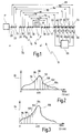
- a first wavelength selector 18 is located at the second fiber section 16 on the output side of fiber length 12 and is centered around the first pump wavelength lambda_1. Accordingly, the first wavelength selector 18 has a high reflectivity at lambda_1 and a lower reflectivity at wavelengths other than lambda_1. As a result, light of wavelength lambda_1 is reflected, whereas light of other wavelengths is allowed to pass.
- a high reflectivity refers to a reflectivity in the range of approximately 80 % to 100 %.
- Raman laser 10 comprises, further, second wavelength selectors 20, 22, 24, 26, 28 and 30 and third wavelength selectors 32, 34 and 36 in the first fiber section 14 on the input side of fiber length 12.
- Fourth wavelength selectors 38, 40 and 42 and fifth wavelength selectors 44, 46, 48, 50, 52 and 54 are arranged in the second fiber section 16 at the output side of fiber length 12.
- Wavelength selectors 18 to 42 have a constant high reflectivity.
- the reflectivity of the fifth wavelength selectors 44 to 54 is adjustable by actuators 56, 58, 60, 62, 64 and 66 that are controlled by a control unit 68.
- the actuators 56 to 66 may be realized as piezo actuators that induce mechanical stress on the wavelength selectors 44 to 54, thereby changing the reflectivity of each of the concerned wavelength selectors 44 to 54 in a controllable manner. It is per se known that the reflectivity of certain wavelength selectors can be changed by mechanical stress or heat. Other means for inducing stress or heat may be utilized alternatively and/or supplementary.
- All wavelength selectors 18 to 54 may be realized as fiber Bragg gratings.
- a fiber Bragg grating is, as is well known in the art, a periodic variation of the refractive index of the fiber core along the length of the fiber.
- the principal property of fiber Bragg gratings is that they reflect light in a narrow bandwidth that is centered around the Bragg wavelength.
- the refractive index variations may be formed by exposing the fiber core to an intense optical interference pattern of ultraviolet light.
- the reflectivity of a strong fiber Bragg grating can approach 100 % at the Bragg wavelength. Light at wavelengths longer or shorter than the Bragg wavelength passes through the Bragg grating with negligible loss.
- the fiber Bragg gratings may be manufactured individually or in groups in respective sections of fiber lengths which may be fused or spliced together and fused or spliced to the fiber length 12 of Raman laser 10.
- pump light emitted by the pump source 17 is fed into the fiber length comprising the first section 14 and the fiber length 12 up to the location of the first wavelength selector 18.
- the Bragg wavelength of first wavelength selector 18 corresponds to the pump wavelength lambda_1. Accordingly, the residual part of pump light incident on first wavelength selector 18 is reflected back.
- the pump light that propagates from the pump source 17 to the first wavelength selector 18 and the reflected pump light that propagates from the first wavelength selector 18 back in the direction to the pump light source 17 is subject to Raman interaction with the matter of fiber length 12.
- a monochromatic and intense pump light beam of pump wavelength lambda_1 equal to 1117 nm generates a gain spectrum of the form that is shown in Fig. 2.
- a small fraction of this broad gain spectrum is selected by wavelength selectors 36 and 38, which show a high reflectivity in a wavelength range close to the maximum of the broad gain spectrum.
- Wavelength selectors 34 and 40 have a high reflectivity and close a second cavity 74. Lasing may occur in cavity 74 at 1248 nm, i.e. one Stokes apart from the preceding Stokes wavelength of 1179 nm. Likewise, wavelength selectors 32 and 42 form a third cavity 76, in which lasing may occur at a wavelength of 1326 nm, i.e. one Stokes apart from the previous Stokes of 1248 nm.
- the monochromatic and intense pumplight beam of 1117 nm that has been emitted by pump source 17 is successively downshifted in frequency by means of the Raman effect in the first cavity 72, the second cavity 74 and the third cavity 76.
- These cavities 72, 74 and 76 are provided with wavelength selectors 32 to 42 of a high reflectivity at their respective input ends and output ends. Accordingly, these cavities 72, 74 and 76 do not provide any output wavelength of Raman laser 10.
- the output wavelengths of multi-output wavelength Raman laser 10 are provided by further cavities 78 to 88.
- the fourth cavity 78 is closed by wavelength selectors 30 and 44
- the fifth cavity 80 is closed by wavelength selectors 28 and 46
- the sixth cavity 82 is closed by wavelength selectors 26 and 48
- the seventh cavity 84 is closed by wavelength selectors 24 and 50
- the eighth cavity 86 is closed by wavelength selectors 22 and 52
- the ninth cavity is closed by wavelength selectors 20 and 54.
- Cavities 78 to 88 may allow lasing at wavelengths of 1415 nm, 1440 nm, 1467 nm, 1427 nm, 1455 nm and 1480 nm, respectively. These wavelengths are output wavelengths of multi-output-wavelength Raman laser 10 because the fifth wavelength selectors 44 to 54 that close the cavities 78 to 88 at the second section 16 on the output side of fiber length 12 have a lower reflectivity that allows light of these frequencies to be transmitted through the fifth wavelength selectors 44 to 54.
- a lower reflectivity refers to a reflectivity below 80 %, in particular to a reflectivity below 60 %.
- the gain spectrum of such a Stokes is shown in Fig. 2, which shows, qualitatively, the Raman efficiency versus the Raman shift for the previous Stokes 90.
- the Raman efficiency as given by curve 92 is measured in arbitrary units and the Raman shift is measured in terms of wave numbers per cm. Curve 92 can be considered as representing the energy distribution of the Raman-scattered light over the respective wave number inside the fiber.
- the gain spectrum of Fig. 2 shows that a certain wavelength range near a Raman shift of 400 periods per cm is more favoured, i.e. more intense, in the gain spectrum than the rest of the spectrum.
- the gain spectrum gives the value of the Raman gain for each output wavelength.
- the Raman gain may be considered as an indicator for the potential power of a respective output wavelength. However, the actual output power depends also on the reflectivities of the wavelength selectors that are involved and may show large deviations from the potential power that is reflected in the gain spectrum.
- Lines 94 to 104 correspond to the wavelengths that have been selected by cavities 78 to 88.
- the points of intersection between lines 94 to 104 and the Raman shift axis designate the individual Raman shift values of these wavelengths in relation to the previous Stokes of 1351 nm. Accordingly, with a given wavelength of the previous Stokes, these points of intersection define the individual wavelengths.
- the height of curve 92 above these points of intersection indicates, according to a first approximation, the potential power of each of these wavelengths in relation to another one of these wavelengths. The potential power is understood as the power inside the cavities.
- line 98 which lies closest to the maximum of curve 92 represents the potentially most powerful wavelength.
- line 94 represents the shortest selected wavelength and lines 96, 100, 102 and 104 represent the remaining selected wavelengths.
- the remaining selected wavelengths according to lines 96 to 104 lie within the gain spectrum 106 of line 94. Therefore, line 94 represents a previous Stokes of a higher order for the wavelengths of lines 96 to 104.
- energy is transferred from the shortest selected wavelength that corresponds to line 94 to longer selected wavelengths by means of the Raman effect.
- Shorter wavelengths e.g. the 1415 nm wave
- the shorter wavelengths generate, by means of the Raman effect, their own Stokes (gain spectrum).
- the longer wavelengths of Fig. 1 gain additional (relative) power at the expense of the power of the shorter wavelengths.
- this effect is self adjusting.
- the effect is used in the invention for controllably adjusting the relative power in each output wavelength according to the needed configuration depending on the line fiber to pump.
- Fig. 2 The distribution and height of lines 94 to 104 in Fig. 2 correspond to the wavelengths and their potential power, respectively.
- the potential power is understood as the relative power inside the cavities.
- the powers of the respective output beams will, in general, be distributed in a different configuration. This effect is due to the fact, that the power of the output beams does not depend on the distribution of relative powers inside the cavities alone, but depends also on the reflectivity of each output coupler that is involved.
- Fig. 4 shows a typical initial distribution of output powers for an arbitrary initial configuration of output coupler reflectivity. It should be noted that the individual lines 94, 96, 98, 100, 102 and 104 represent a certain power that corresponds to a line's height. In Fig. 4, the potentially most powerful line 98 is even more powerful than in Fig. 2. This effect may be generated by a transfer of power of shorter wavelengths to the wavelength of line 98. Such a transfer has been described above with reference to Fig. 3.
- the reflectivity of both wavelength selectors that close the cavity in which the potentially most powerful wavelength resonates has to be nearly optimal in the arbitrary configuration to result in such a powerful output wavelength.
- the remaining output wavelengths are even less powerful than could be expected in view of Fig. 2. This effect may be due to a sub-optimal reflectivity of each wavelength selector involved.
- the initial arbitrary distribution is adjusted stepwise in a general manner that is applicable to any multi output wavelength Raman laser having more than two output wavelengths.
- Such a general method according to the invention is shown exemplarily by the flow chart of Fig. 5.
- Control unit 68 controls the actuators 56 to 66 in accordance with the steps of the flow chart.
- the relative output power of the potentially most powerful wavelength is suppressed in a first step 108.
- the power of the 1440 nm wave of Fig. 1 is, in a first step, suppressed by lowering the reflection of the respective wavelength selector.
- to suppress the wavelength means that this wavelength is not allowed to lase. In other words: It is suppressed below the lasing threshold by a lowered reflectivity that increases its threshold.
- step 108 line 98 disappears, or shrinks to zero, as shown in Fig. 6.
- the other selected wavelengths lines 94, 96, 100, 102 and 104 gain power when line 98 is suppressed. This may be due to the effect that the power that was previously preferably concentrated in line 98, may be distributed, to a certain extent, to the other lines in the absence of line 98.
- the relative output power of the shortest output wavelength, that is line 94 is adjusted. The result of this step is shown in Fig. 7.
- the adjustment of line 94 to the value shown in Fig. 7 enhances the power of the longer wavelengths as a result of the effect described with regard to Fig. 3.
- the adjustment is done on the shortest wavelength in order to get power in this wavelength as well as in all above wavelengths except the wavelength of line 98 (i.e. the potentially most powerful wavelength). This is accomplished by optimising the reflectivities of the concerned wavelength selectors in order to promote lasing in the concerned cavity.
- a third step 112 the relative output power of further output wavelengths is adjusted.
- the result is shown in Fig. 8.
- the output power distribution of Fig. 8 clearly shows an enhanced degree of uniformity.
- the power is then individually adjusted in all the different wavelengths except for the wavelength of line 98.
- the power of line 98 is adjusted to the desired power in a fourth step 114.
- this step 114 the previously suppressed wavelength of line 98 is allowed to resonate again by an adjustment of the respective wavelength selector. It has been observed, that the power level of the remaining lines decreases as a result of allowing enhancement of the potentially most powerful line. Again, the mechanism described in view of Fig. 3 may cause this effect.
- Fig. 8 shows an output wavelength power distribution having a good degree of uniformity as was desired in this particular example. Other power distributions may be generated by the method according to the invention by varying the amount of change allowed in each step.
- the order of the steps is important to achieve the desired result.
- it is important to suppress the potentially most powerful line in the first step.
- the other wavelengths may not be able to lase, as all power is preferably absorbed by the potentially most powerful wavelength which has the maximum gain from the Stokes 90 at 1351 nm.
- the output wavelengths of 1415 nm, 1440, 1467 nm, 1427 nm, 1455 nm and 1480 nm are located in the broad gain spectrum of the previous Stokes, i. e. the wavelength that resonates in the third cavity 76.
- the output wavelengths of 1415 nm, 1440, 1467 nm, 1427 nm, 1455 nm and 1480 nm are located in the broad gain spectrum of the previous Stokes, i. e. the wavelength that resonates in the third cavity 76.
- the output wavelengths of 1415 nm, 1440, 1467 nm, 1427 nm, 1455 nm and 1480 nm are located in the broad gain spectrum of the previous Stokes, i. e. the wavelength that resonates in the third cavity 76.
- the output wavelengths of 1415 nm, 1440, 1467 nm, 1427 nm, 1455 nm and 1480 nm are located in the broad gain spectrum
- the invention is not limited to a multiple output Raman laser device having six output wavelengths.
Landscapes
- Physics & Mathematics (AREA)
- Electromagnetism (AREA)
- Engineering & Computer Science (AREA)
- Plasma & Fusion (AREA)
- Optics & Photonics (AREA)
- Lasers (AREA)
- Optical Modulation, Optical Deflection, Nonlinear Optics, Optical Demodulation, Optical Logic Elements (AREA)
- Spectrometry And Color Measurement (AREA)
Priority Applications (4)
| Application Number | Priority Date | Filing Date | Title |
|---|---|---|---|
| DE60310382T DE60310382T2 (de) | 2003-05-28 | 2003-05-28 | Verfahren zur Adjustierung des Spektrums eines vielwellenlängen Raman Lasers |
| AT03291296T ATE348426T1 (de) | 2003-05-28 | 2003-05-28 | Verfahren zur adjustierung des spektrums eines vielwellenlängen raman lasers |
| EP03291296A EP1482609B1 (fr) | 2003-05-28 | 2003-05-28 | Méthode de contrôle de la sortie spectrale d'un laser à l'effet Raman à multiple longueur d'onde |
| US10/827,274 US7042916B2 (en) | 2003-05-28 | 2004-04-20 | Method for adjusting the output spectrum of a multi-output-wavelength Raman laser |
Applications Claiming Priority (1)
| Application Number | Priority Date | Filing Date | Title |
|---|---|---|---|
| EP03291296A EP1482609B1 (fr) | 2003-05-28 | 2003-05-28 | Méthode de contrôle de la sortie spectrale d'un laser à l'effet Raman à multiple longueur d'onde |
Publications (2)
| Publication Number | Publication Date |
|---|---|
| EP1482609A1 true EP1482609A1 (fr) | 2004-12-01 |
| EP1482609B1 EP1482609B1 (fr) | 2006-12-13 |
Family
ID=33104213
Family Applications (1)
| Application Number | Title | Priority Date | Filing Date |
|---|---|---|---|
| EP03291296A Expired - Lifetime EP1482609B1 (fr) | 2003-05-28 | 2003-05-28 | Méthode de contrôle de la sortie spectrale d'un laser à l'effet Raman à multiple longueur d'onde |
Country Status (4)
| Country | Link |
|---|---|
| US (1) | US7042916B2 (fr) |
| EP (1) | EP1482609B1 (fr) |
| AT (1) | ATE348426T1 (fr) |
| DE (1) | DE60310382T2 (fr) |
Cited By (3)
| Publication number | Priority date | Publication date | Assignee | Title |
|---|---|---|---|---|
| WO2011063364A1 (fr) * | 2009-11-23 | 2011-05-26 | Lockheed Martin Corporation | Système laser à combinaison spectrale de faisceaux et procédé pour générer des longueurs d'onde moins dangereuses pour les yeux |
| EP2430714A4 (fr) * | 2009-05-11 | 2013-07-03 | Ofs Fitel Llc | Fibre à filtre destinée à être utilisée dans des applications d'émission laser raman et ses techniques de fabrication |
| US9366872B2 (en) | 2014-02-18 | 2016-06-14 | Lockheed Martin Corporation | Apparatus and method for fiber-laser output-beam shaping for spectral beam combination |
Families Citing this family (8)
| Publication number | Priority date | Publication date | Assignee | Title |
|---|---|---|---|---|
| US7391561B2 (en) | 2005-07-29 | 2008-06-24 | Aculight Corporation | Fiber- or rod-based optical source featuring a large-core, rare-earth-doped photonic-crystal device for generation of high-power pulsed radiation and method |
| US7768700B1 (en) | 2006-11-30 | 2010-08-03 | Lockheed Martin Corporation | Method and apparatus for optical gain fiber having segments of differing core sizes |
| US8179594B1 (en) | 2007-06-29 | 2012-05-15 | Lockheed Martin Corporation | Method and apparatus for spectral-beam combining of fanned-in laser beams with chromatic-dispersion compensation using a plurality of diffractive gratings |
| JP5323562B2 (ja) * | 2008-03-31 | 2013-10-23 | 古河電気工業株式会社 | カスケードラマンレーザ |
| US8503840B2 (en) | 2010-08-23 | 2013-08-06 | Lockheed Martin Corporation | Optical-fiber array method and apparatus |
| DE112011101288T5 (de) | 2010-04-12 | 2013-02-07 | Lockheed Martin Corporation | Strahldiagnostik- und Rückkopplungssystem sowie Verfahren für spektralstrahlkombinierteLaser |
| US9835778B1 (en) | 2013-09-13 | 2017-12-05 | Lockheed Martin Corporation | Apparatus and method for a diamond substrate for a multi-layered dielectric diffraction grating |
| WO2020107030A1 (fr) * | 2018-11-23 | 2020-05-28 | Nuburu, Inc | Source laser visible à longueurs d'onde multiples |
Citations (2)
| Publication number | Priority date | Publication date | Assignee | Title |
|---|---|---|---|---|
| US6239902B1 (en) * | 1998-03-24 | 2001-05-29 | Xtera Communciations Inc. | Nonlinear fiber amplifiers used for a 1430-1530nm low-loss window in optical fibers |
| US6407855B1 (en) * | 1999-10-29 | 2002-06-18 | Sdl, Inc. | Multiple wavelength optical sources |
-
2003
- 2003-05-28 EP EP03291296A patent/EP1482609B1/fr not_active Expired - Lifetime
- 2003-05-28 DE DE60310382T patent/DE60310382T2/de not_active Expired - Lifetime
- 2003-05-28 AT AT03291296T patent/ATE348426T1/de not_active IP Right Cessation
-
2004
- 2004-04-20 US US10/827,274 patent/US7042916B2/en not_active Expired - Lifetime
Patent Citations (2)
| Publication number | Priority date | Publication date | Assignee | Title |
|---|---|---|---|---|
| US6239902B1 (en) * | 1998-03-24 | 2001-05-29 | Xtera Communciations Inc. | Nonlinear fiber amplifiers used for a 1430-1530nm low-loss window in optical fibers |
| US6407855B1 (en) * | 1999-10-29 | 2002-06-18 | Sdl, Inc. | Multiple wavelength optical sources |
Non-Patent Citations (2)
| Title |
|---|
| MERMELSTEIN M D ET AL: "A high-efficiency power-stable three-wavelength configurable raman fiber laser", OPTICAL FIBER COMMUNICATION CONFERENCE. (OFC). TECHNICAL DIGEST POSTCONFERENCE EDITION. ANAHEIM, CA, MARCH 17 - 22, 2001, TRENDS IN OPTICS AND PHOTONICS SERIES. TOPS. VOLUME 54, WASHINGTON, WA: OSA, US, vol. 1 OF 4, 17 March 2001 (2001-03-17), pages PD31 - PD33, XP010545688, ISBN: 1-55752-655-9 * |
| MERMELSTEIN M D ET AL: "CONFIGURABLE THREE-WAVELENGTH RAMAN FIBER LASER FOR RAMAN AMPLIFICATION AND DYNAMIC GAIN FLATTENING", IEEE PHOTONICS TECHNOLOGY LETTERS, IEEE INC. NEW YORK, US, vol. 13, no. 12, December 2001 (2001-12-01), pages 1286 - 1288, XP001076759, ISSN: 1041-1135 * |
Cited By (4)
| Publication number | Priority date | Publication date | Assignee | Title |
|---|---|---|---|---|
| EP2430714A4 (fr) * | 2009-05-11 | 2013-07-03 | Ofs Fitel Llc | Fibre à filtre destinée à être utilisée dans des applications d'émission laser raman et ses techniques de fabrication |
| WO2011063364A1 (fr) * | 2009-11-23 | 2011-05-26 | Lockheed Martin Corporation | Système laser à combinaison spectrale de faisceaux et procédé pour générer des longueurs d'onde moins dangereuses pour les yeux |
| US9366872B2 (en) | 2014-02-18 | 2016-06-14 | Lockheed Martin Corporation | Apparatus and method for fiber-laser output-beam shaping for spectral beam combination |
| US9927621B2 (en) | 2014-02-18 | 2018-03-27 | Lockheed Martin Corporation | Method and apparatus for fiber-laser output-beam shaping for beam combination |
Also Published As
| Publication number | Publication date |
|---|---|
| EP1482609B1 (fr) | 2006-12-13 |
| DE60310382T2 (de) | 2007-04-12 |
| US7042916B2 (en) | 2006-05-09 |
| US20040240487A1 (en) | 2004-12-02 |
| DE60310382D1 (de) | 2007-01-25 |
| ATE348426T1 (de) | 2007-01-15 |
Similar Documents
| Publication | Publication Date | Title |
|---|---|---|
| USRE48899E1 (en) | Slanted FBG for SRS suppression | |
| US8441718B2 (en) | Spectrally beam combined laser system and method at eye-safer wavelengths | |
| US6965469B2 (en) | Fiber amplifier having a non-doped inner core and at least one doped gain region | |
| US6807338B2 (en) | Multiwavelength cascaded raman resonator | |
| US7042916B2 (en) | Method for adjusting the output spectrum of a multi-output-wavelength Raman laser | |
| DE60310363T2 (de) | Raman Faserlaser mit mehrwellenlängiger, stabiler, kleiner Ausgangsleistung für Anwendungen als Seed-Laser | |
| US6768750B2 (en) | Multi-spectral line Raman laser | |
| US6392789B1 (en) | Erbium-doped optical fiber having gratings formed therein and fabrication method thereof | |
| US6836488B2 (en) | Cascaded Raman fiber laser, and optical system including such a laser | |
| EP1553666B1 (fr) | Laser raman cascadé avec réflecteur appari | |
| CN110663146B (zh) | 大功率包层泵浦单模光纤拉曼激光器 | |
| KR20260005240A (ko) | 광섬유 및 광섬유 디바이스 | |
| Chang et al. | Dual-wavelength cascaded Raman fibre laser | |
| Headley et al. | Raman fiber lasers | |
| US20050078715A1 (en) | Raman laser with a simplified structure of wavelength selectors | |
| Chang et al. | Cascaded Raman fibre laser for stable dual-wavelength operation | |
| US20030184848A1 (en) | Raman fiber amplification stage, optical system and method to control the Raman amplification | |
| Cierullies et al. | Experimental and numerical study of the switching dynamics of Raman fiber lasers | |
| GB2380313A (en) | Raman Device | |
| Chang et al. | Dual-wavelength cascaded Raman fiber laser | |
| WO2003052884A2 (fr) | Sources de rayonnement optique et leurs procedes de generation | |
| Khodasevich et al. | Gain equalization filter on the base of a nonlinear Fabry-Perot interferometer for WDM systems | |
| JP2003043269A (ja) | 光ファイバグレーティング、光ファイバグレーティングの反射波長制御方法及び光部品 |
Legal Events
| Date | Code | Title | Description |
|---|---|---|---|
| PUAI | Public reference made under article 153(3) epc to a published international application that has entered the european phase |
Free format text: ORIGINAL CODE: 0009012 |
|
| 17P | Request for examination filed |
Effective date: 20040528 |
|
| AK | Designated contracting states |
Kind code of ref document: A1 Designated state(s): AT BE BG CH CY CZ DE DK EE ES FI FR GB GR HU IE IT LI LU MC NL PT RO SE SI SK TR |
|
| AX | Request for extension of the european patent |
Extension state: AL LT LV MK |
|
| AKX | Designation fees paid |
Designated state(s): AT BE BG CH CY CZ DE DK EE ES FI FR GB GR HU IE IT LI LU MC NL PT RO SE SI SK TR |
|
| GRAP | Despatch of communication of intention to grant a patent |
Free format text: ORIGINAL CODE: EPIDOSNIGR1 |
|
| GRAS | Grant fee paid |
Free format text: ORIGINAL CODE: EPIDOSNIGR3 |
|
| GRAA | (expected) grant |
Free format text: ORIGINAL CODE: 0009210 |
|
| AK | Designated contracting states |
Kind code of ref document: B1 Designated state(s): AT BE BG CH CY CZ DE DK EE ES FI FR GB GR HU IE IT LI LU MC NL PT RO SE SI SK TR |
|
| PG25 | Lapsed in a contracting state [announced via postgrant information from national office to epo] |
Ref country code: SI Free format text: LAPSE BECAUSE OF FAILURE TO SUBMIT A TRANSLATION OF THE DESCRIPTION OR TO PAY THE FEE WITHIN THE PRESCRIBED TIME-LIMIT Effective date: 20061213 Ref country code: CH Free format text: LAPSE BECAUSE OF FAILURE TO SUBMIT A TRANSLATION OF THE DESCRIPTION OR TO PAY THE FEE WITHIN THE PRESCRIBED TIME-LIMIT Effective date: 20061213 Ref country code: DK Free format text: LAPSE BECAUSE OF FAILURE TO SUBMIT A TRANSLATION OF THE DESCRIPTION OR TO PAY THE FEE WITHIN THE PRESCRIBED TIME-LIMIT Effective date: 20061213 Ref country code: CZ Free format text: LAPSE BECAUSE OF FAILURE TO SUBMIT A TRANSLATION OF THE DESCRIPTION OR TO PAY THE FEE WITHIN THE PRESCRIBED TIME-LIMIT Effective date: 20061213 Ref country code: SK Free format text: LAPSE BECAUSE OF FAILURE TO SUBMIT A TRANSLATION OF THE DESCRIPTION OR TO PAY THE FEE WITHIN THE PRESCRIBED TIME-LIMIT Effective date: 20061213 Ref country code: BE Free format text: LAPSE BECAUSE OF FAILURE TO SUBMIT A TRANSLATION OF THE DESCRIPTION OR TO PAY THE FEE WITHIN THE PRESCRIBED TIME-LIMIT Effective date: 20061213 Ref country code: AT Free format text: LAPSE BECAUSE OF FAILURE TO SUBMIT A TRANSLATION OF THE DESCRIPTION OR TO PAY THE FEE WITHIN THE PRESCRIBED TIME-LIMIT Effective date: 20061213 Ref country code: FI Free format text: LAPSE BECAUSE OF FAILURE TO SUBMIT A TRANSLATION OF THE DESCRIPTION OR TO PAY THE FEE WITHIN THE PRESCRIBED TIME-LIMIT Effective date: 20061213 Ref country code: NL Free format text: LAPSE BECAUSE OF FAILURE TO SUBMIT A TRANSLATION OF THE DESCRIPTION OR TO PAY THE FEE WITHIN THE PRESCRIBED TIME-LIMIT Effective date: 20061213 Ref country code: LI Free format text: LAPSE BECAUSE OF FAILURE TO SUBMIT A TRANSLATION OF THE DESCRIPTION OR TO PAY THE FEE WITHIN THE PRESCRIBED TIME-LIMIT Effective date: 20061213 Ref country code: RO Free format text: LAPSE BECAUSE OF FAILURE TO SUBMIT A TRANSLATION OF THE DESCRIPTION OR TO PAY THE FEE WITHIN THE PRESCRIBED TIME-LIMIT Effective date: 20061213 |
|
| REG | Reference to a national code |
Ref country code: GB Ref legal event code: FG4D |
|
| REG | Reference to a national code |
Ref country code: CH Ref legal event code: EP |
|
| REG | Reference to a national code |
Ref country code: IE Ref legal event code: FG4D |
|
| REF | Corresponds to: |
Ref document number: 60310382 Country of ref document: DE Date of ref document: 20070125 Kind code of ref document: P |
|
| PG25 | Lapsed in a contracting state [announced via postgrant information from national office to epo] |
Ref country code: SE Free format text: LAPSE BECAUSE OF FAILURE TO SUBMIT A TRANSLATION OF THE DESCRIPTION OR TO PAY THE FEE WITHIN THE PRESCRIBED TIME-LIMIT Effective date: 20070313 Ref country code: BG Free format text: LAPSE BECAUSE OF FAILURE TO SUBMIT A TRANSLATION OF THE DESCRIPTION OR TO PAY THE FEE WITHIN THE PRESCRIBED TIME-LIMIT Effective date: 20070313 |
|
| PG25 | Lapsed in a contracting state [announced via postgrant information from national office to epo] |
Ref country code: ES Free format text: LAPSE BECAUSE OF FAILURE TO SUBMIT A TRANSLATION OF THE DESCRIPTION OR TO PAY THE FEE WITHIN THE PRESCRIBED TIME-LIMIT Effective date: 20070324 |
|
| RAP2 | Party data changed (patent owner data changed or rights of a patent transferred) |
Owner name: ALCATEL LUCENT |
|
| PG25 | Lapsed in a contracting state [announced via postgrant information from national office to epo] |
Ref country code: PT Free format text: LAPSE BECAUSE OF FAILURE TO SUBMIT A TRANSLATION OF THE DESCRIPTION OR TO PAY THE FEE WITHIN THE PRESCRIBED TIME-LIMIT Effective date: 20070514 |
|
| NLV1 | Nl: lapsed or annulled due to failure to fulfill the requirements of art. 29p and 29m of the patents act | ||
| ET | Fr: translation filed | ||
| REG | Reference to a national code |
Ref country code: CH Ref legal event code: PL |
|
| PLBE | No opposition filed within time limit |
Free format text: ORIGINAL CODE: 0009261 |
|
| STAA | Information on the status of an ep patent application or granted ep patent |
Free format text: STATUS: NO OPPOSITION FILED WITHIN TIME LIMIT |
|
| 26N | No opposition filed |
Effective date: 20070914 |
|
| PG25 | Lapsed in a contracting state [announced via postgrant information from national office to epo] |
Ref country code: MC Free format text: LAPSE BECAUSE OF NON-PAYMENT OF DUE FEES Effective date: 20070531 |
|
| PG25 | Lapsed in a contracting state [announced via postgrant information from national office to epo] |
Ref country code: GR Free format text: LAPSE BECAUSE OF FAILURE TO SUBMIT A TRANSLATION OF THE DESCRIPTION OR TO PAY THE FEE WITHIN THE PRESCRIBED TIME-LIMIT Effective date: 20070314 |
|
| PG25 | Lapsed in a contracting state [announced via postgrant information from national office to epo] |
Ref country code: IE Free format text: LAPSE BECAUSE OF NON-PAYMENT OF DUE FEES Effective date: 20070528 |
|
| PG25 | Lapsed in a contracting state [announced via postgrant information from national office to epo] |
Ref country code: EE Free format text: LAPSE BECAUSE OF FAILURE TO SUBMIT A TRANSLATION OF THE DESCRIPTION OR TO PAY THE FEE WITHIN THE PRESCRIBED TIME-LIMIT Effective date: 20061213 |
|
| PG25 | Lapsed in a contracting state [announced via postgrant information from national office to epo] |
Ref country code: LU Free format text: LAPSE BECAUSE OF NON-PAYMENT OF DUE FEES Effective date: 20070528 Ref country code: CY Free format text: LAPSE BECAUSE OF FAILURE TO SUBMIT A TRANSLATION OF THE DESCRIPTION OR TO PAY THE FEE WITHIN THE PRESCRIBED TIME-LIMIT Effective date: 20061213 |
|
| PG25 | Lapsed in a contracting state [announced via postgrant information from national office to epo] |
Ref country code: TR Free format text: LAPSE BECAUSE OF FAILURE TO SUBMIT A TRANSLATION OF THE DESCRIPTION OR TO PAY THE FEE WITHIN THE PRESCRIBED TIME-LIMIT Effective date: 20061213 Ref country code: HU Free format text: LAPSE BECAUSE OF FAILURE TO SUBMIT A TRANSLATION OF THE DESCRIPTION OR TO PAY THE FEE WITHIN THE PRESCRIBED TIME-LIMIT Effective date: 20070614 |
|
| PGFP | Annual fee paid to national office [announced via postgrant information from national office to epo] |
Ref country code: IT Payment date: 20110523 Year of fee payment: 9 |
|
| PG25 | Lapsed in a contracting state [announced via postgrant information from national office to epo] |
Ref country code: IT Free format text: LAPSE BECAUSE OF NON-PAYMENT OF DUE FEES Effective date: 20120528 |
|
| REG | Reference to a national code |
Ref country code: FR Ref legal event code: GC Effective date: 20140717 |
|
| REG | Reference to a national code |
Ref country code: FR Ref legal event code: PLFP Year of fee payment: 13 |
|
| REG | Reference to a national code |
Ref country code: FR Ref legal event code: CA Effective date: 20150521 |
|
| REG | Reference to a national code |
Ref country code: FR Ref legal event code: CA Effective date: 20150521 |
|
| REG | Reference to a national code |
Ref country code: FR Ref legal event code: PLFP Year of fee payment: 14 |
|
| PGFP | Annual fee paid to national office [announced via postgrant information from national office to epo] |
Ref country code: GB Payment date: 20160520 Year of fee payment: 14 Ref country code: DE Payment date: 20160520 Year of fee payment: 14 |
|
| PGFP | Annual fee paid to national office [announced via postgrant information from national office to epo] |
Ref country code: FR Payment date: 20160520 Year of fee payment: 14 |
|
| REG | Reference to a national code |
Ref country code: DE Ref legal event code: R119 Ref document number: 60310382 Country of ref document: DE |
|
| GBPC | Gb: european patent ceased through non-payment of renewal fee |
Effective date: 20170528 |
|
| REG | Reference to a national code |
Ref country code: FR Ref legal event code: ST Effective date: 20180131 |
|
| PG25 | Lapsed in a contracting state [announced via postgrant information from national office to epo] |
Ref country code: DE Free format text: LAPSE BECAUSE OF NON-PAYMENT OF DUE FEES Effective date: 20171201 Ref country code: GB Free format text: LAPSE BECAUSE OF NON-PAYMENT OF DUE FEES Effective date: 20170528 |
|
| PG25 | Lapsed in a contracting state [announced via postgrant information from national office to epo] |
Ref country code: FR Free format text: LAPSE BECAUSE OF NON-PAYMENT OF DUE FEES Effective date: 20170531 |