EP1482655A2 - Utilisation d'antennes directionnelles pour la réduction d'effets d'interférence dans des réseaux sans fil - Google Patents
Utilisation d'antennes directionnelles pour la réduction d'effets d'interférence dans des réseaux sans fil Download PDFInfo
- Publication number
- EP1482655A2 EP1482655A2 EP04010930A EP04010930A EP1482655A2 EP 1482655 A2 EP1482655 A2 EP 1482655A2 EP 04010930 A EP04010930 A EP 04010930A EP 04010930 A EP04010930 A EP 04010930A EP 1482655 A2 EP1482655 A2 EP 1482655A2
- Authority
- EP
- European Patent Office
- Prior art keywords
- wireless device
- act
- antenna
- frequency spectrum
- channel
- Prior art date
- Legal status (The legal status is an assumption and is not a legal conclusion. Google has not performed a legal analysis and makes no representation as to the accuracy of the status listed.)
- Withdrawn
Links
Images


Classifications
-
- H—ELECTRICITY
- H01—ELECTRIC ELEMENTS
- H01Q—ANTENNAS, i.e. RADIO AERIALS
- H01Q3/00—Arrangements for changing or varying the orientation or the shape of the directional pattern of the waves radiated from an antenna or antenna system
- H01Q3/26—Arrangements for changing or varying the orientation or the shape of the directional pattern of the waves radiated from an antenna or antenna system varying the relative phase or relative amplitude of energisation between two or more active radiating elements; varying the distribution of energy across a radiating aperture
- H01Q3/267—Phased-array testing or checking devices
-
- H—ELECTRICITY
- H01—ELECTRIC ELEMENTS
- H01Q—ANTENNAS, i.e. RADIO AERIALS
- H01Q1/00—Details of, or arrangements associated with, antennas
- H01Q1/12—Supports; Mounting means
- H01Q1/22—Supports; Mounting means by structural association with other equipment or articles
- H01Q1/24—Supports; Mounting means by structural association with other equipment or articles with receiving set
- H01Q1/241—Supports; Mounting means by structural association with other equipment or articles with receiving set used in mobile communications, e.g. GSM
- H01Q1/242—Supports; Mounting means by structural association with other equipment or articles with receiving set used in mobile communications, e.g. GSM specially adapted for hand-held use
-
- H—ELECTRICITY
- H01—ELECTRIC ELEMENTS
- H01Q—ANTENNAS, i.e. RADIO AERIALS
- H01Q3/00—Arrangements for changing or varying the orientation or the shape of the directional pattern of the waves radiated from an antenna or antenna system
- H01Q3/22—Arrangements for changing or varying the orientation or the shape of the directional pattern of the waves radiated from an antenna or antenna system varying the orientation in accordance with variation of frequency of radiated wave
-
- H—ELECTRICITY
- H04—ELECTRIC COMMUNICATION TECHNIQUE
- H04B—TRANSMISSION
- H04B7/00—Radio transmission systems, i.e. using radiation field
- H04B7/02—Diversity systems; Multi-antenna system, i.e. transmission or reception using multiple antennas
- H04B7/04—Diversity systems; Multi-antenna system, i.e. transmission or reception using multiple antennas using two or more spaced independent antennas
- H04B7/0408—Diversity systems; Multi-antenna system, i.e. transmission or reception using multiple antennas using two or more spaced independent antennas using two or more beams, i.e. beam diversity
-
- H—ELECTRICITY
- H04—ELECTRIC COMMUNICATION TECHNIQUE
- H04W—WIRELESS COMMUNICATION NETWORKS
- H04W16/00—Network planning, e.g. coverage or traffic planning tools; Network deployment, e.g. resource partitioning or cells structures
- H04W16/14—Spectrum sharing arrangements between different networks
-
- H—ELECTRICITY
- H04—ELECTRIC COMMUNICATION TECHNIQUE
- H04W—WIRELESS COMMUNICATION NETWORKS
- H04W16/00—Network planning, e.g. coverage or traffic planning tools; Network deployment, e.g. resource partitioning or cells structures
- H04W16/24—Cell structures
-
- H—ELECTRICITY
- H04—ELECTRIC COMMUNICATION TECHNIQUE
- H04W—WIRELESS COMMUNICATION NETWORKS
- H04W16/00—Network planning, e.g. coverage or traffic planning tools; Network deployment, e.g. resource partitioning or cells structures
- H04W16/24—Cell structures
- H04W16/28—Cell structures using beam steering
-
- H—ELECTRICITY
- H04—ELECTRIC COMMUNICATION TECHNIQUE
- H04W—WIRELESS COMMUNICATION NETWORKS
- H04W40/00—Communication routing or communication path finding
- H04W40/02—Communication route or path selection, e.g. power-based or shortest path routing
-
- H—ELECTRICITY
- H04—ELECTRIC COMMUNICATION TECHNIQUE
- H04W—WIRELESS COMMUNICATION NETWORKS
- H04W72/00—Local resource management
- H04W72/02—Selection of wireless resources by user or terminal
-
- Y—GENERAL TAGGING OF NEW TECHNOLOGICAL DEVELOPMENTS; GENERAL TAGGING OF CROSS-SECTIONAL TECHNOLOGIES SPANNING OVER SEVERAL SECTIONS OF THE IPC; TECHNICAL SUBJECTS COVERED BY FORMER USPC CROSS-REFERENCE ART COLLECTIONS [XRACs] AND DIGESTS
- Y02—TECHNOLOGIES OR APPLICATIONS FOR MITIGATION OR ADAPTATION AGAINST CLIMATE CHANGE
- Y02D—CLIMATE CHANGE MITIGATION TECHNOLOGIES IN INFORMATION AND COMMUNICATION TECHNOLOGIES [ICT], I.E. INFORMATION AND COMMUNICATION TECHNOLOGIES AIMING AT THE REDUCTION OF THEIR OWN ENERGY USE
- Y02D30/00—Reducing energy consumption in communication networks
- Y02D30/70—Reducing energy consumption in communication networks in wireless communication networks
Definitions
- the present invention relates to wireless networks, and more specifically, to using directional antennas to mitigate interference in wireless networks.
- Computer systems and related technology affect many aspects of society. Indeed, the computer system's ability to process information has transformed the way we live and work. Computer systems now commonly perform a host of tasks (e.g., word processing, scheduling, and database management) that prior to the advent of the computer system were performed manually. More recently, computer systems have been coupled to one another to form both wired and wireless computer networks over which the computer systems can communicate electronically to share data. As a result, many tasks performed at a computer system (e.g., voice communication, accessing electronic mail, electronic conferencing, web browsing) include electronic communication with one or more other computer systems via wired and/or wireless computer networks.
- tasks performed at a computer system e.g., voice communication, accessing electronic mail, electronic conferencing, web browsing
- a number of computer systems can be coupled to a data hub through corresponding wired connections (e.g., category 5 cable) to form a wired network (e.g., an Ethernet segment).
- a number of wireless computer systems can be coupled to a wireless access point ("AP") through corresponding wireless connections (e.g., resulting from appropriate communication between radio transmitters and receivers) to form a wireless network (e.g., an IEEE 802.11 network).
- AP wireless access point
- a data hub and/or an AP can be connected to other data hubs, APs, or other network devices, such as routers, gateways, and switches to form more complex networks (including both wired and wireless connections).
- the Open System Interconnect (“OSI") model is an example of a networking framework for implementing a protocol stack.
- the OSI model breaks down the operations for transferring electronic data into seven distinct "layers," each designated to perform certain operations in the data transfer process. While protocol stacks can potentially implement each of the layers, many protocol stacks implement only selective layers for use in transferring electronic data across a network.
- the physical layer When data is received from a network it enters the physical layer and is passed up to higher intermediate layers and then eventually received at an application layer.
- the physical layer the lower most layer, is responsible for converting electrical impulses, light, or radio waves into a bit stream and vice versa.
- data when data is transmitted from a computer system, it originates at the application layer and is passed down to intermediate lower layers and then onto a network.
- the application layer the upper most layer, is responsible for supporting applications and end-user processes, such as, for example, electronic conferencing software, electronic mail clients, web browsers, etc.
- the Data Link layer decodes data packets (received from higher layers) into bit streams for use by the physical layer and encodes bit steams (received from the physical layer) into data packets for use by higher layers.
- a sub-layer typically included in the Data Link layer is the Media Access Control ("MAC") layer, which implements protocols for moving data packets onto a shared channel (e.g., an Ethernet segment or an IEEE 802.11 channel).
- MAC Media Access Control
- Access points typically include an omni-directional antenna that essentially results in spherical region around the access point.
- the omni-directional antenna enables the access point to meaningfully send data to and receive data from the station. That is, within the particular range, transmitted radio signals have sufficient signal strength such that a physical layer can convert the radio signals into a bit stream.
- wireless devices communicate in unlicensed frequency bands (e.g., in the 2.4 GHz band). Communication between wireless devices operating in unlicensed bands can be degraded do to transmissions from other devices that operate in the same unlicensed band. For example, some cordless telephones, some microwaves, BlueTooth devices, a wide variety of control devices, and IEEE 802.11b devices all operate in the 2.4 GHz band. Thus, cordless phones, microwaves, BlueTooth devices, and control devices (hereinafter referred to as "interfering devices”) can interfere with communication between an IEEE 802.11b station and an IEEE 802.11b access point.
- interfering devices can interfere with communication between an IEEE 802.11b station and an IEEE 802.11b access point.
- IEEE 802.11b effectively has three channels that can be used for communication between an IEEE 802.11b access point and IEEE 802.11b station. Thus, when there is increased interference one IEEE 802.11b channel, interference can potentially be reduced by switching to another IEEE 802.11b channel. However, since there are effectively only three channels, it is often difficult, if not impossible, to find a channel that has reduced interference at every location within a spherical region surrounding an IEEE 802.11b access point. A first channel may have increased interference on one direction, a second channel may have increased interference in a second direction, and a third channel may have increased interference in a third direction. Unfortunately, as typically implemented an omni-directional antenna can only be tuned to one channel at a time. Thus, if an IEEE 802.11b station is located in each of the first, second, and third directions, there would be virtually no way for an omni-directional antenna to select a channel such that each IEEE 802.11b station could communicate with reduced interference.
- Interference from interfering devices can degrade the speed and reliability of data transferred between an IEEE 802.11b station and an IEEE 802.11b access point. For example, interference from an interfering device at or near an IEEE 802.11b station can cause the IEEE 802.11b station to communicate at a significantly reduced data rate (and, if the interfering device has high gain, potentially make communication impossible). Further, when an interfering device is at or near an IEEE 802.1 lb access point, communication with a number of associated IEEE 802.11b stations can be degraded. Signal degradation due to interference may result in an omni-directional antenna being able to detect that radio waves are being received but may make it impossible to determine what data is being represented by the radio waves. That is, a physical layer may not be able to generate a bit stream from the degraded radio waves. Therefore systems, methods, and computer program products for mitigating the effects of interference during wireless communication would be advantageous.
- An antenna device includes an omni-directional antenna and at least one directional antenna.
- Each directional antenna e.g., an electronically steered phased array antenna
- the antenna device can be an access point computer system that provides wireless devices with access to a network, such as, for example, to a Local Area Network or even to the Internet.
- the omni-directional antenna receives a data notification signal from a wireless device.
- the data notification signal represents that the wireless device has program data to send to the antenna device.
- the antenna device detects the usage of a frequency spectrum in the direction of the wireless device. For example, the antenna device may detect usage in a 2.4 GHz spectrum or a 5 GHz spectrum in the direction of the wireless device
- the antenna device selects a channel in the frequency spectrum for use in receiving program data from the wireless device based on the results of the detection of current usage. For example, based on detection of current usage, the antenna device can select a wireless channel that has reduced interference. When appropriate, a directional beam from a directional antenna is directed towards the wireless device. The antenna device uses the directional antenna to receive program data from the wireless device on the selected channel in response to having received the data notification signal.
- the omni-directional antenna transmits a location request that requests the location of a wireless device.
- the omni-directional antenna receives a corresponding location signal, which indicates the location of the wireless device, from the wireless device.
- the antenna device detects the usage of a frequency spectrum in the direction of the wireless device.
- the antenna device selects a channel in the frequency spectrum for use in sending program data to the wireless device based on the results of the detection of current usage.
- a directional beam from a directional antenna is directed towards the wireless device.
- the antenna device uses the directional antenna to send program data to the wireless device on the selected channel in response to having received the location signal.
- program data is defined as data that is not associated with the control of an antenna device.
- Program data includes Web data, file transfer data, streaming audio/video (“AN”) data, or other information that may be exchanged between applications.
- Program data may be associated with more restrictive transmission requirements, such as, for example, increased bandwidth requirements, increased reliability, and reduced latency, relative to control data.
- Program data can be sent and/or received using a wide range of protocols, such as, for example, Internet Protocol (“IP”) and Transmission Control Protocol (“TCP").
- IP Internet Protocol
- TCP Transmission Control Protocol
- Omni-directional antenna 206 and directional antenna 207 are connected to control module 218 by corresponding links 214 and 216 respectively.
- Links 214 and 216 can be part of a system bus (e.g., bus 110) or Local Area Network ("LAN") connection.
- Control module 218 can send program data to and receive program data from omni-directional antenna 206 and directional antenna 207 over the corresponding links 214 and 216.
- Control module 218 can also send control data, such as, for example, antenna commands, to omni-directional antenna 206 and directional antenna 207 over the corresponding links 214 and 216.
- Antenna commands can cause the configuration of omni-directional antenna 206 and directional antenna 207 to change (e.g., to cause directional antenna 207 to direct a directional beam at a wireless device). Accordingly, control module 218 can interoperate with omni-directional antenna 206 and directional antenna 207 to implement the principles of the present invention.
- control module 218 can cause omni-directional antenna 206 to listen for data notification signals indicating that a wireless device has data to send to antenna device 201. When omni-directional antenna 206 receives a data notification signal, control module 218 can then cause a directional beam of directional antenna 207 to be directed towards the location of a wireless device. Further, when antenna device 203 has data to send to a wireless device, control module 218 can cause omni-directional antenna 206 to transmit a location request and listen for a corresponding location signal. Control module 218 can process a corresponding location signal and cause a directional beam to be directed towards the location of a wireless device. Control module 218 can also cause omni-directional antenna 206 and/or directional antenna 207 to measure usage of a frequency spectrum (e.g., a 2.4 GHz or 5 GHz spectrum) and to communicate on a particular channel within the frequency spectrum.
- a frequency spectrum e.g., a 2.4 GHz or 5 GHz spectrum
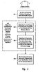
- FIG. 3 illustrates an example flowchart of a method 300 for an antenna device to receive program data in accordance with the principles of the present invention.
- the method 300 will be discussed with respect to the antenna device, wireless devices, cordless telephone, and device depicted in network architecture 200.
- the method 300 includes an act of an omni-directional antenna receiving a data notification signal (act 301).
- Act 301 can include an omni-directional antenna receiving a data notification signal from a wireless device.
- omni-directional antenna 206 can receive a data notification signal from wireless device 227.
- a data notification signal can be indicative of a wireless device having program data to transmit to an antenna device.
- a data notification signal from wireless device 227 can be indicative of wireless device 227 having program data to send to antenna device 203.
- a data notification signal can be one or more bytes (e.g., of a request to send (“RTS”) signal) that indicate to an antenna device that the wireless device has program data to send.
- RTS request to send
- the method 300 includes a functional, result-oriented step for configuring a directional antenna to receive data on a selected channel based on, interference in a frequency spectrum (step 305).
- Step 305 can include any corresponding acts for configuring a directional antenna to receive data on a selected channel based on interference in a frequency spectrum.
- step 305 includes a corresponding act of detecting current usage of a frequency spectrum in the direction of the wireless device (act 302.)
- Act 302 can include the antenna device detecting current usage of a frequency spectrum in the direction of the wireless device.
- a received data notification signal can indicate to a control module that a wireless device has program data to send to an antenna device.
- the control module can send antenna commands to cause an omni-directional antenna or a directional antenna (e.g., selected from among one or more directional antennas at the antenna device) to detect usage of a frequency spectrum.
- control module can 218 can send antenna commands to cause omni-directional antenna 206 and/or directional antenna 207 to detect usage of a frequency spectrum (e.g., a 2.4 GHz frequency spectrum or 5 GHz frequency spectrum) in the direction of the wireless device 227.
- a frequency spectrum e.g., a 2.4 GHz frequency spectrum or 5 GHz frequency spectrum
- cordless telephone 238 interferes with a portion of a frequency spectrum. For example, if cordless phone 238 operates in the 2.4 GHz frequency spectrum, cordless telephone 238 may emit noise within some portion of the 2.4 GHz frequency spectrum (e.g., in a range between 2.401 GHz and 2.473 GHz). If antenna device 203 and wireless device 227 communicate on frequencies in the 2.4 GHz frequency spectrum, noise emitted from cordless phone 238 can potentially interfere with communication between antenna device 203 and wireless device 227.
- cordless telephone 238 may emit noise at or near a frequency 2.412 GHz (a frequency that corresponds to IEEE 802.11b channel 1) that degrades communication between antenna device 203 and wireless device 227 when they attempt to communicate on the 2.412 GHz frequency.
- antenna device 203 can detect increased usage (in the direction of wireless device 227) at or near 2.412 GHz as compared to noise detected at other frequencies in the 2.4 GHz frequency spectrum (e.g., at or near 2.437 GHz or at or near 2.462 GHz, etc).
- device 248 interferes with a portion of a frequency spectrum. For example, if device 248 operates in the 5 GHz frequency spectrum, device 248 may emit noise within some portion of the 5 GHz frequency spectrum (e.g., in a range between 5.17 GHz and 5.805 GHz). If antenna device 203 and wireless device 228 communicate on frequencies in the 5 GHz frequency spectrum, noise emitted from device 248 can potentially interfere with communication between antenna device 203 and wireless device 248. For example, device 248 may emit noise at or near a frequency of 5.22 GHz (a frequency that corresponds to IEEE 802.11a channel 44) that degrades communication between antenna device 203 and wireless device 227 when they attempt to communicate on the 5.22 GHz frequency.
- 5.22 GHz a frequency that corresponds to IEEE 802.11a channel 44
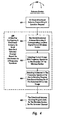
- control module 218 can cause a directional beam from directional antenna 207 to be directed at a wireless device. For example, when wireless device 227 has program data to send to antenna device 203 but no directional beam is currently directed at wireless device 227, control module 218 can cause a directional beam 252A to be directed at wireless device 227. Similarly, when wireless device 228 has program data to send to antenna device 203 but no directional beam is currently directed at wireless device 228, control module 218 can cause a directional beam 252C to be directed at wireless device 228.
- antenna device 203 uses directional beams to communicate, a wireless channel can be selected to mitigate interference in the direction of a wireless device.
- communication is not limited to a channel used by omni-directional antenna 206.
- antenna device 203 can select channels to mitigate interface with different wireless devices based on the location of the wireless devices relative to antenna device 203.
- a wireless device does not receive a location request due to interference on a channel being used the wireless device. For example, communication with wireless device 227 may be significantly degraded due to interference form cordless telephone 238.
- a wireless device may receive a location request.
- omni-directional antenna 203 may have sufficient strength to cause a location request reach wireless device 228.
- wireless device 228 can respond to the location request by sending a location signal back to antenna device 203.
- wireless device 228 can transmit a location signal indicating the location of wireless device 228.
- the location signal may be one or more bytes (e.g., of a clear to send (“CTS") signal) that indicate to the antenna device that the wireless device can receive program data.
- the location signal can include location data representing the location of the wireless device relative to the antenna device.
- Control module 218 can process the location data to calculate the location of wireless device 228. Alternately, control module 218 may at least estimate the location of the wireless device based on the direction from which the location signal was received.
- control module can 218 can send antenna commands to cause omni-directional antenna 206 and/or directional antenna 207 to detect usage of a frequency spectrum (e.g., a 2.4 GHz frequency spectrum or 5 GHz frequency spectrum) in the direction of the wireless device 228.
- a frequency spectrum e.g., a 2.4 GHz frequency spectrum or 5 GHz frequency spectrum
- antenna device 203 is a multi-mode access point computer system. That is, antenna device 203 can communicate with wireless devices in a plurality of different frequency spectrums simultaneously. Accordingly, different directional beams can be used to communicate with wireless devices in each different frequency spectrum. For example in Figure 2, directional beam 252A may be used for communication in a 2.4 GHz frequency spectrum and directional beam 252C may be used for communication in a 5 GHz frequency spectrum. Accordingly, antenna device 203 can be configured to simultaneously communicate with a plurality of wireless devices, even when some wireless devices communicate in a first frequency spectrum and other wireless devices communicate in a second different frequency spectrum. When appropriate, antenna device 203 can include a different directional antenna for each different frequency spectrum.
Landscapes
- Engineering & Computer Science (AREA)
- Computer Networks & Wireless Communication (AREA)
- Signal Processing (AREA)
- Mobile Radio Communication Systems (AREA)
Applications Claiming Priority (2)
| Application Number | Priority Date | Filing Date | Title |
|---|---|---|---|
| US449451 | 2003-05-30 | ||
| US10/449,451 US7130586B2 (en) | 2003-05-30 | 2003-05-30 | Using directional antennas to mitigate the effects of interference in wireless networks |
Publications (2)
| Publication Number | Publication Date |
|---|---|
| EP1482655A2 true EP1482655A2 (fr) | 2004-12-01 |
| EP1482655A3 EP1482655A3 (fr) | 2011-03-16 |
Family
ID=33131635
Family Applications (1)
| Application Number | Title | Priority Date | Filing Date |
|---|---|---|---|
| EP04010930A Withdrawn EP1482655A3 (fr) | 2003-05-30 | 2004-05-07 | Utilisation d'antennes directionnelles pour la réduction d'effets d'interférence dans des réseaux sans fil |
Country Status (5)
| Country | Link |
|---|---|
| US (1) | US7130586B2 (fr) |
| EP (1) | EP1482655A3 (fr) |
| JP (1) | JP4597581B2 (fr) |
| KR (1) | KR101087422B1 (fr) |
| CN (1) | CN1574713B (fr) |
Cited By (1)
| Publication number | Priority date | Publication date | Assignee | Title |
|---|---|---|---|---|
| WO2014133902A1 (fr) * | 2013-02-26 | 2014-09-04 | Qualcomm Incorporated | Dispositif sans fil à réseau d'antennes et antenne séparée |
Families Citing this family (78)
| Publication number | Priority date | Publication date | Assignee | Title |
|---|---|---|---|---|
| EP1389884A1 (fr) * | 2002-08-13 | 2004-02-18 | Siemens Aktiengesellschaft | Méthode de fonctionnement d'un système de radio utilisant antennes directionnelles et station emittant et système de radio |
| US7295806B2 (en) * | 2003-05-30 | 2007-11-13 | Microsoft Corporation | Using directional antennas to enhance wireless mesh networks |
| US7609648B2 (en) * | 2003-06-19 | 2009-10-27 | Ipr Licensing, Inc. | Antenna steering for an access point based upon control frames |
| US20040266356A1 (en) * | 2003-06-27 | 2004-12-30 | Javor Ronald D. | Multiple antenna apparatus and method to provide interference detection and cancellation |
| JP2005026733A (ja) * | 2003-06-30 | 2005-01-27 | Hitachi Ltd | 無線通信装置および無線通信方法 |
| GB2404820B (en) * | 2003-08-06 | 2005-07-20 | Toshiba Res Europ Ltd | Improved wireless local area network security |
| US20050058111A1 (en) * | 2003-09-15 | 2005-03-17 | Pai-Fu Hung | WLAN device having smart antenna system |
| FR2861231A1 (fr) * | 2003-10-20 | 2005-04-22 | Thomson Licensing Sa | Methode de communication dans un reseau de communication sans fil |
| US7428428B2 (en) * | 2004-04-28 | 2008-09-23 | Hong Kong Applied Science And Technology Research Institute Co., Ltd. | Systems and methods for wireless network range extension |
| JP2005341232A (ja) * | 2004-05-27 | 2005-12-08 | Toshiba Corp | サーバ装置、クライアント装置および通信制御方法 |
| US8934416B2 (en) * | 2005-03-09 | 2015-01-13 | Xirrus, Inc. | System for allocating channels in a multi-radio wireless LAN array |
| JP4416704B2 (ja) * | 2005-07-01 | 2010-02-17 | シャープ株式会社 | 無線伝送システム |
| US8429502B2 (en) * | 2005-11-16 | 2013-04-23 | Qualcomm Incorporated | Frame format for millimeter-wave systems |
| US8910027B2 (en) * | 2005-11-16 | 2014-12-09 | Qualcomm Incorporated | Golay-code generation |
| US8583995B2 (en) * | 2005-11-16 | 2013-11-12 | Qualcomm Incorporated | Multi-mode processor |
| US8036653B2 (en) * | 2006-05-23 | 2011-10-11 | The Boeing Company | Establishing and conducting communications within a network |
| US20070297365A1 (en) * | 2006-06-27 | 2007-12-27 | Li Guoqing C | Control message exchange for wireless devices using directional and omni-directional transmissions |
| US8433368B2 (en) | 2006-12-20 | 2013-04-30 | General Instrument Corporation | Active link cable mesh |
| US9088907B2 (en) * | 2007-06-18 | 2015-07-21 | Xirrus, Inc. | Node fault identification in wireless LAN access points |
| US8472497B2 (en) * | 2007-10-10 | 2013-06-25 | Qualcomm Incorporated | Millimeter wave beaconing with directional antennas |
| US8856628B2 (en) * | 2007-10-10 | 2014-10-07 | Qualcomm Incorporated | Method and apparatus for generation and usage of extended golay codes |
| KR100943531B1 (ko) | 2007-12-20 | 2010-02-22 | 성균관대학교산학협력단 | 무선 광통신 장치 및 방법 |
| US8483620B2 (en) * | 2008-02-07 | 2013-07-09 | Qualcomm Incorporated | Asynchronous interference management |
| US20090203320A1 (en) * | 2008-02-07 | 2009-08-13 | Qualcomm Incorporated | Asynchronous interference management based on timeslot overlap |
| US9094986B2 (en) * | 2008-02-07 | 2015-07-28 | Qualcomm, Incorporated | Synchronous and asynchronous interference management |
| US8482478B2 (en) * | 2008-11-12 | 2013-07-09 | Xirrus, Inc. | MIMO antenna system |
| US8744364B2 (en) | 2008-11-26 | 2014-06-03 | Nec Corporation | Wireless station apparatus, wireless communication system, and wireless communication control method |
| KR100935714B1 (ko) * | 2009-05-04 | 2010-01-08 | 현광전자통신 주식회사 | 이중 안테나와 수신구조를 사용하는 디지털 방식의 고주파 전자신호 분석 시스템 |
| US8630582B2 (en) * | 2009-09-02 | 2014-01-14 | Sony Corporation | Out-of-band radio link protocol and network architecture for a wireless network composed of wireless terminals with millimetre wave frequency range radio units |
| KR101016033B1 (ko) * | 2010-06-29 | 2011-02-23 | 엘아이지넥스원 주식회사 | 복합식 안테나 장치 |
| US8830854B2 (en) | 2011-07-28 | 2014-09-09 | Xirrus, Inc. | System and method for managing parallel processing of network packets in a wireless access device |
| US8868002B2 (en) | 2011-08-31 | 2014-10-21 | Xirrus, Inc. | System and method for conducting wireless site surveys |
| US9055450B2 (en) | 2011-09-23 | 2015-06-09 | Xirrus, Inc. | System and method for determining the location of a station in a wireless environment |
| US8620348B2 (en) * | 2012-01-24 | 2013-12-31 | Nokia Corporation | Directional peer-to-peer networking |
| JP5435111B2 (ja) * | 2012-03-30 | 2014-03-05 | 横河電機株式会社 | 通信装置、通信システム及び通信方法 |
| US20140180938A1 (en) * | 2012-12-26 | 2014-06-26 | Verizon Patent And Licensing Inc. | License application processor for telecommunications equipment |
| US9531067B2 (en) | 2013-02-08 | 2016-12-27 | Ubiquiti Networks, Inc. | Adjustable-tilt housing with flattened dome shape, array antenna, and bracket mount |
| US9930592B2 (en) | 2013-02-19 | 2018-03-27 | Mimosa Networks, Inc. | Systems and methods for directing mobile device connectivity |
| US9179336B2 (en) | 2013-02-19 | 2015-11-03 | Mimosa Networks, Inc. | WiFi management interface for microwave radio and reset to factory defaults |
| US9130305B2 (en) | 2013-03-06 | 2015-09-08 | Mimosa Networks, Inc. | Waterproof apparatus for cables and cable interfaces |
| WO2014138292A1 (fr) | 2013-03-06 | 2014-09-12 | Mimosa Networks, Inc. | Enceinte pour radio, antenne à réflecteur parabolique, et blindages de lobe secondaire |
| US10742275B2 (en) * | 2013-03-07 | 2020-08-11 | Mimosa Networks, Inc. | Quad-sector antenna using circular polarization |
| US9191081B2 (en) | 2013-03-08 | 2015-11-17 | Mimosa Networks, Inc. | System and method for dual-band backhaul radio |
| US9295103B2 (en) | 2013-05-30 | 2016-03-22 | Mimosa Networks, Inc. | Wireless access points providing hybrid 802.11 and scheduled priority access communications |
| KR101994325B1 (ko) * | 2013-05-31 | 2019-09-30 | 삼성전자주식회사 | 통신 시스템에서 어레이 안테나 장치 및 그 제어 방법 |
| US10938110B2 (en) | 2013-06-28 | 2021-03-02 | Mimosa Networks, Inc. | Ellipticity reduction in circularly polarized array antennas |
| WO2015038178A1 (fr) * | 2013-09-11 | 2015-03-19 | Intel Corporation | Partitionnement dynamique d'architectures de réseau à commande de phase modulaire pour utilisations multiples |
| US9001689B1 (en) | 2014-01-24 | 2015-04-07 | Mimosa Networks, Inc. | Channel optimization in half duplex communications systems |
| US9780892B2 (en) | 2014-03-05 | 2017-10-03 | Mimosa Networks, Inc. | System and method for aligning a radio using an automated audio guide |
| EP3114884B1 (fr) | 2014-03-07 | 2019-10-23 | Ubiquiti Inc. | Identification et authentification d'un dispositif de nuage informatique |
| US9998246B2 (en) | 2014-03-13 | 2018-06-12 | Mimosa Networks, Inc. | Simultaneous transmission on shared channel |
| CN105993183B (zh) | 2014-06-30 | 2019-08-13 | 优倍快网络公司 | 用于在无线电网络的配置中使用功能图协助的方法和工具 |
| US10182438B2 (en) | 2014-08-31 | 2019-01-15 | Ubiquiti Networks, Inc. | Methods and apparatuses for graphically indicating station efficiency and pseudo-dynamic error vector magnitude information for a network of wireless stations |
| US10958332B2 (en) | 2014-09-08 | 2021-03-23 | Mimosa Networks, Inc. | Wi-Fi hotspot repeater |
| KR102325737B1 (ko) * | 2014-12-03 | 2021-11-15 | 삼성전자주식회사 | 통신을 수행하는 전자 장치 및 방법 |
| GB2539732A (en) | 2015-06-25 | 2016-12-28 | Airspan Networks Inc | A configurable antenna and method of operating such a configurable antenna |
| GB2539730B (en) | 2015-06-25 | 2021-04-07 | Airspan Ip Holdco Llc | Node role assignment in networks |
| GB2539731B (en) | 2015-06-25 | 2021-08-04 | Airspan Ip Holdco Llc | Quality of service in wireless backhauls |
| GB2539727B (en) | 2015-06-25 | 2021-05-12 | Airspan Ip Holdco Llc | A configurable antenna and method of operating such a configurable antenna |
| WO2016207603A1 (fr) | 2015-06-25 | 2016-12-29 | Airspan Networks Inc. | Gestion d'interférence externe dans un réseau sans fil |
| GB2539736A (en) | 2015-06-25 | 2016-12-28 | Airspan Networks Inc | Wireless network configuration using path loss determination between nodes |
| GB2539735A (en) | 2015-06-25 | 2016-12-28 | Airspan Networks Inc | Sub-sampling antenna elements |
| GB2539722B (en) | 2015-06-25 | 2021-10-13 | Airspan Ip Holdco Llc | Bearing calculation |
| GB2539734A (en) | 2015-06-25 | 2016-12-28 | Airspan Networks Inc | An antenna apparatus and method of performing spatial nulling within the antenna apparatus |
| GB2539733A (en) | 2015-06-25 | 2016-12-28 | Airspan Networks Inc | An antenna apparatus and method of configuring a transmission beam for the antenna apparatus |
| US9680704B2 (en) | 2015-09-25 | 2017-06-13 | Ubiquiti Networks, Inc. | Compact and integrated key controller apparatus for monitoring networks |
| KR101756307B1 (ko) * | 2015-10-15 | 2017-07-10 | 현대자동차주식회사 | 안테나 장치, 이를 포함하는 차량 및 안테나 장치의 제어 방법 |
| US10476153B2 (en) * | 2015-12-22 | 2019-11-12 | Taoglas Group Holdings Limited | Directional antenna with signal strength feedback and methods |
| WO2017123558A1 (fr) | 2016-01-11 | 2017-07-20 | Mimosa Networks, Inc. | Antenne montée sur une carte de circuit imprimé et interface de guide d'ondes |
| EP3491697B8 (fr) | 2016-07-29 | 2023-10-18 | Mimosa Networks, Inc. | Réseau d'antennes à point d'accès multibandes |
| US11317415B2 (en) * | 2017-08-17 | 2022-04-26 | Apple Inc. | Selecting resources for sidelink communication based on geo-location information |
| US10511074B2 (en) | 2018-01-05 | 2019-12-17 | Mimosa Networks, Inc. | Higher signal isolation solutions for printed circuit board mounted antenna and waveguide interface |
| US11069986B2 (en) | 2018-03-02 | 2021-07-20 | Airspan Ip Holdco Llc | Omni-directional orthogonally-polarized antenna system for MIMO applications |
| KR102262165B1 (ko) * | 2018-08-08 | 2021-06-09 | 삼성전자주식회사 | 입력 장치와의 통신 연결을 제어하는 전자 장치 및 그 제어 방법 |
| US11289821B2 (en) | 2018-09-11 | 2022-03-29 | Air Span Ip Holdco Llc | Sector antenna systems and methods for providing high gain and high side-lobe rejection |
| CN111244606B (zh) * | 2020-02-21 | 2022-07-05 | 京东方科技集团股份有限公司 | 发射天线系统、接收天线系统及通信设备 |
| CN113382336B (zh) * | 2021-06-09 | 2024-02-02 | 歌尔智能科技有限公司 | 一种天线控制方法、装置和系统 |
| JP2024112654A (ja) * | 2023-02-08 | 2024-08-21 | 株式会社東芝 | 通信中継システム、通信中継方法及びプログラム |
Family Cites Families (18)
| Publication number | Priority date | Publication date | Assignee | Title |
|---|---|---|---|---|
| JPH03131130A (ja) * | 1989-10-17 | 1991-06-04 | Nippon Telegr & Teleph Corp <Ntt> | チャネル指定制御方法 |
| FR2705849B1 (fr) * | 1993-05-28 | 1995-06-30 | Alcatel Mobile Comm France | Station de base d'un réseau cellulaire de type GSM, et procédé d'échange de données entre cette station de base et un mobile évoluant dans le réseau. |
| JP3265877B2 (ja) * | 1994-12-14 | 2002-03-18 | 日本電信電話株式会社 | 無線通信方法及び装置 |
| US5835859A (en) * | 1995-10-13 | 1998-11-10 | Airnet Communications Corporation | Method for frequency allocation and assignment in wireless communication systems |
| JP3224189B2 (ja) * | 1995-11-27 | 2001-10-29 | モトローラ株式会社 | 通信システム |
| CA2166343C (fr) * | 1995-12-29 | 1999-08-10 | Lee F. Hartley | Reseau a acces multiple par detection de porteuse et evitement de collision avec interruption automatique |
| US5924040A (en) * | 1996-11-20 | 1999-07-13 | Telxon Corporation | Wireless communication system having base station with adjustable power transceiver for locating mobile devices |
| JP3308835B2 (ja) * | 1996-12-06 | 2002-07-29 | 株式会社日立製作所 | 無線通信システム |
| GB0030932D0 (en) * | 2000-12-19 | 2001-01-31 | Radiant Networks Plc | Antenna apparatus, communications apparatus and method of transmission |
| US6990338B2 (en) * | 2001-06-11 | 2006-01-24 | The Boeing Company | Mobile wireless local area network and related methods |
| JP3665628B2 (ja) * | 2001-08-07 | 2005-06-29 | 株式会社東芝 | 無線通信システム及び無線端末装置 |
| US7224685B2 (en) * | 2001-09-13 | 2007-05-29 | Ipr Licensing, Inc. | Method of detection of signals using an adaptive antenna in a peer-to-peer network |
| JP4094835B2 (ja) * | 2001-09-27 | 2008-06-04 | 三井金属鉱業株式会社 | 低酸素フッ化タンタル酸カリウム結晶及び低酸素フッ化ニオブ酸カリウム結晶の製造方法、これらの製造方法で得られた低酸素フッ化ニオブ酸カリウム結晶、並びにフッ化タンタル酸カリウム結晶及びフッ化ニオブ酸カリウム結晶の酸素分析方法 |
| US20040002357A1 (en) * | 2002-06-25 | 2004-01-01 | Mathilde Benveniste | Directional antennas and wireless channel access |
| US7062296B2 (en) * | 2002-11-04 | 2006-06-13 | Vivato, Inc. | Forced beam switching in wireless communication systems having smart antennas |
| AU2003285138A1 (en) * | 2002-11-04 | 2004-06-07 | Vivato Inc | Directed wireless communication |
| US20040166881A1 (en) * | 2003-02-06 | 2004-08-26 | Farchmin David Walter | Phased array wireless location method and apparatus |
| US7239894B2 (en) * | 2003-05-30 | 2007-07-03 | Microsoft Corporation | Using directional antennas to enhance throughput in wireless networks |
-
2003
- 2003-05-30 US US10/449,451 patent/US7130586B2/en not_active Expired - Fee Related
-
2004
- 2004-05-07 EP EP04010930A patent/EP1482655A3/fr not_active Withdrawn
- 2004-05-26 JP JP2004156805A patent/JP4597581B2/ja not_active Expired - Fee Related
- 2004-05-28 CN CN2004100474377A patent/CN1574713B/zh not_active Expired - Fee Related
- 2004-05-29 KR KR1020040038665A patent/KR101087422B1/ko not_active Expired - Fee Related
Cited By (2)
| Publication number | Priority date | Publication date | Assignee | Title |
|---|---|---|---|---|
| WO2014133902A1 (fr) * | 2013-02-26 | 2014-09-04 | Qualcomm Incorporated | Dispositif sans fil à réseau d'antennes et antenne séparée |
| US9490548B2 (en) | 2013-02-26 | 2016-11-08 | Qualcomm Incorporated | Wireless device with antenna array and separate antenna |
Also Published As
| Publication number | Publication date |
|---|---|
| KR20040103463A (ko) | 2004-12-08 |
| CN1574713B (zh) | 2010-05-26 |
| EP1482655A3 (fr) | 2011-03-16 |
| US7130586B2 (en) | 2006-10-31 |
| KR101087422B1 (ko) | 2011-11-25 |
| JP4597581B2 (ja) | 2010-12-15 |
| CN1574713A (zh) | 2005-02-02 |
| US20040242274A1 (en) | 2004-12-02 |
| JP2004364285A (ja) | 2004-12-24 |
Similar Documents
| Publication | Publication Date | Title |
|---|---|---|
| US7130586B2 (en) | Using directional antennas to mitigate the effects of interference in wireless networks | |
| US7239894B2 (en) | Using directional antennas to enhance throughput in wireless networks | |
| EP1482657B1 (fr) | Emploi d'antennes directionneles pour améliorer réseaux sans fil | |
| US7349422B2 (en) | Providing contention free quality of service to time constrained data | |
| US8238832B1 (en) | Antenna optimum beam forming for multiple protocol coexistence on a wireless device | |
| US11445476B2 (en) | Devices, systems, and methods for predicting communication channel conditions | |
| US8116285B1 (en) | Intelligent wireless access point selection | |
| US20080008109A1 (en) | Method and apparatus for bridging wireless control networks | |
| CN1813448A (zh) | 用于多信道无线lan体系结构的方法和装置 | |
| EP2748939A1 (fr) | Dispositif, système et procédé de commande de communication sans fil en fonction d'une caractéristique liée à l'orientation d'un dispositif de communication sans fil | |
| US10455564B2 (en) | Simultaneous channel switching within a mesh network | |
| JP5145433B2 (ja) | ミリ波wpanにおける干渉を回避しチャネル効率を高めるメカニズム | |
| WO2019157825A1 (fr) | Procédé de transmission de données et dispositif associé | |
| CN102355290A (zh) | 基于智能天线技术的无线多跳网络数据发送、接收方法 | |
| CN1615608A (zh) | 能够执行无线通信的设备 | |
| JP6016667B2 (ja) | 通信装置及びコンピュータプログラム | |
| WO2025145250A1 (fr) | Procédés et modules de fourniture de qualité de service dans une adaptation de liaison | |
| US20150131490A1 (en) | Bidirectional Voice Transmission System and Method Thereof | |
| HK40107001A (zh) | 基於中继技术的uwb传输方法及电子设备、存储介质 | |
| HK40107001B (zh) | 基於中继技术的uwb传输方法及电子设备、存储介质 | |
| CN118539957A (zh) | 一种波束确定的方法、装置、设备、芯片和存储介质 | |
| King et al. | A measurement study on 802.11 concurrently used for positioning and communications |
Legal Events
| Date | Code | Title | Description |
|---|---|---|---|
| PUAI | Public reference made under article 153(3) epc to a published international application that has entered the european phase |
Free format text: ORIGINAL CODE: 0009012 |
|
| AK | Designated contracting states |
Kind code of ref document: A2 Designated state(s): AT BE BG CH CY CZ DE DK EE ES FI FR GB GR HU IE IT LI LU MC NL PL PT RO SE SI SK TR |
|
| AX | Request for extension of the european patent |
Extension state: AL HR LT LV MK |
|
| PUAL | Search report despatched |
Free format text: ORIGINAL CODE: 0009013 |
|
| AK | Designated contracting states |
Kind code of ref document: A3 Designated state(s): AT BE BG CH CY CZ DE DK EE ES FI FR GB GR HU IE IT LI LU MC NL PL PT RO SE SI SK TR |
|
| AX | Request for extension of the european patent |
Extension state: AL HR LT LV MK |
|
| 17P | Request for examination filed |
Effective date: 20110905 |
|
| AKX | Designation fees paid |
Designated state(s): AT BE BG CH CY CZ DE DK EE ES FI FR GB GR HU IE IT LI LU MC NL PL PT RO SE SI SK TR |
|
| 17Q | First examination report despatched |
Effective date: 20120403 |
|
| STAA | Information on the status of an ep patent application or granted ep patent |
Free format text: STATUS: THE APPLICATION HAS BEEN WITHDRAWN |
|
| 18W | Application withdrawn |
Effective date: 20121015 |