EP1482728A2 - Netzwerk benutzende Aufnahmeverfahren und Aufnahmesystem. - Google Patents
Netzwerk benutzende Aufnahmeverfahren und Aufnahmesystem. Download PDFInfo
- Publication number
- EP1482728A2 EP1482728A2 EP04006244A EP04006244A EP1482728A2 EP 1482728 A2 EP1482728 A2 EP 1482728A2 EP 04006244 A EP04006244 A EP 04006244A EP 04006244 A EP04006244 A EP 04006244A EP 1482728 A2 EP1482728 A2 EP 1482728A2
- Authority
- EP
- European Patent Office
- Prior art keywords
- recording
- information
- recording apparatus
- external
- network
- Prior art date
- Legal status (The legal status is an assumption and is not a legal conclusion. Google has not performed a legal analysis and makes no representation as to the accuracy of the status listed.)
- Withdrawn
Links
Images




Classifications
-
- H—ELECTRICITY
- H04—ELECTRIC COMMUNICATION TECHNIQUE
- H04L—TRANSMISSION OF DIGITAL INFORMATION, e.g. TELEGRAPHIC COMMUNICATION
- H04L12/00—Data switching networks
- H04L12/28—Data switching networks characterised by path configuration, e.g. LAN [Local Area Networks] or WAN [Wide Area Networks]
- H04L12/2803—Home automation networks
-
- H—ELECTRICITY
- H04—ELECTRIC COMMUNICATION TECHNIQUE
- H04N—PICTORIAL COMMUNICATION, e.g. TELEVISION
- H04N21/00—Selective content distribution, e.g. interactive television or video on demand [VOD]
- H04N21/40—Client devices specifically adapted for the reception of or interaction with content, e.g. set-top-box [STB]; Operations thereof
- H04N21/41—Structure of client; Structure of client peripherals
- H04N21/4104—Peripherals receiving signals from specially adapted client devices
- H04N21/4108—Peripherals receiving signals from specially adapted client devices characterised by an identification number or address, e.g. local network address
-
- H—ELECTRICITY
- H04—ELECTRIC COMMUNICATION TECHNIQUE
- H04N—PICTORIAL COMMUNICATION, e.g. TELEVISION
- H04N21/00—Selective content distribution, e.g. interactive television or video on demand [VOD]
- H04N21/40—Client devices specifically adapted for the reception of or interaction with content, e.g. set-top-box [STB]; Operations thereof
- H04N21/41—Structure of client; Structure of client peripherals
- H04N21/4104—Peripherals receiving signals from specially adapted client devices
- H04N21/4113—PC
-
- H—ELECTRICITY
- H04—ELECTRIC COMMUNICATION TECHNIQUE
- H04N—PICTORIAL COMMUNICATION, e.g. TELEVISION
- H04N21/00—Selective content distribution, e.g. interactive television or video on demand [VOD]
- H04N21/40—Client devices specifically adapted for the reception of or interaction with content, e.g. set-top-box [STB]; Operations thereof
- H04N21/41—Structure of client; Structure of client peripherals
- H04N21/4104—Peripherals receiving signals from specially adapted client devices
- H04N21/4135—Peripherals receiving signals from specially adapted client devices external recorder
-
- H—ELECTRICITY
- H04—ELECTRIC COMMUNICATION TECHNIQUE
- H04N—PICTORIAL COMMUNICATION, e.g. TELEVISION
- H04N21/00—Selective content distribution, e.g. interactive television or video on demand [VOD]
- H04N21/40—Client devices specifically adapted for the reception of or interaction with content, e.g. set-top-box [STB]; Operations thereof
- H04N21/41—Structure of client; Structure of client peripherals
- H04N21/426—Internal components of the client ; Characteristics thereof
-
- H—ELECTRICITY
- H04—ELECTRIC COMMUNICATION TECHNIQUE
- H04N—PICTORIAL COMMUNICATION, e.g. TELEVISION
- H04N21/00—Selective content distribution, e.g. interactive television or video on demand [VOD]
- H04N21/40—Client devices specifically adapted for the reception of or interaction with content, e.g. set-top-box [STB]; Operations thereof
- H04N21/43—Processing of content or additional data, e.g. demultiplexing additional data from a digital video stream; Elementary client operations, e.g. monitoring of home network or synchronising decoder's clock; Client middleware
- H04N21/433—Content storage operation, e.g. storage operation in response to a pause request, caching operations
- H04N21/4334—Recording operations
-
- H—ELECTRICITY
- H04—ELECTRIC COMMUNICATION TECHNIQUE
- H04N—PICTORIAL COMMUNICATION, e.g. TELEVISION
- H04N21/00—Selective content distribution, e.g. interactive television or video on demand [VOD]
- H04N21/40—Client devices specifically adapted for the reception of or interaction with content, e.g. set-top-box [STB]; Operations thereof
- H04N21/43—Processing of content or additional data, e.g. demultiplexing additional data from a digital video stream; Elementary client operations, e.g. monitoring of home network or synchronising decoder's clock; Client middleware
- H04N21/435—Processing of additional data, e.g. decrypting of additional data, reconstructing software from modules extracted from the transport stream
-
- H—ELECTRICITY
- H04—ELECTRIC COMMUNICATION TECHNIQUE
- H04N—PICTORIAL COMMUNICATION, e.g. TELEVISION
- H04N21/00—Selective content distribution, e.g. interactive television or video on demand [VOD]
- H04N21/40—Client devices specifically adapted for the reception of or interaction with content, e.g. set-top-box [STB]; Operations thereof
- H04N21/43—Processing of content or additional data, e.g. demultiplexing additional data from a digital video stream; Elementary client operations, e.g. monitoring of home network or synchronising decoder's clock; Client middleware
- H04N21/436—Interfacing a local distribution network, e.g. communicating with another STB or one or more peripheral devices inside the home
- H04N21/43615—Interfacing a Home Network, e.g. for connecting the client to a plurality of peripherals
-
- H—ELECTRICITY
- H04—ELECTRIC COMMUNICATION TECHNIQUE
- H04N—PICTORIAL COMMUNICATION, e.g. TELEVISION
- H04N21/00—Selective content distribution, e.g. interactive television or video on demand [VOD]
- H04N21/40—Client devices specifically adapted for the reception of or interaction with content, e.g. set-top-box [STB]; Operations thereof
- H04N21/43—Processing of content or additional data, e.g. demultiplexing additional data from a digital video stream; Elementary client operations, e.g. monitoring of home network or synchronising decoder's clock; Client middleware
- H04N21/438—Interfacing the downstream path of the transmission network originating from a server, e.g. retrieving encoded video stream packets from an IP network
- H04N21/4383—Accessing a communication channel
-
- H—ELECTRICITY
- H04—ELECTRIC COMMUNICATION TECHNIQUE
- H04N—PICTORIAL COMMUNICATION, e.g. TELEVISION
- H04N21/00—Selective content distribution, e.g. interactive television or video on demand [VOD]
- H04N21/40—Client devices specifically adapted for the reception of or interaction with content, e.g. set-top-box [STB]; Operations thereof
- H04N21/45—Management operations performed by the client for facilitating the reception of or the interaction with the content or administrating data related to the end-user or to the client device itself, e.g. learning user preferences for recommending movies, resolving scheduling conflicts
- H04N21/462—Content or additional data management e.g. creating a master electronic programme guide from data received from the Internet and a Head-end or controlling the complexity of a video stream by scaling the resolution or bit-rate based on the client capabilities
- H04N21/4622—Retrieving content or additional data from different sources, e.g. from a broadcast channel and the Internet
-
- H—ELECTRICITY
- H04—ELECTRIC COMMUNICATION TECHNIQUE
- H04N—PICTORIAL COMMUNICATION, e.g. TELEVISION
- H04N21/00—Selective content distribution, e.g. interactive television or video on demand [VOD]
- H04N21/40—Client devices specifically adapted for the reception of or interaction with content, e.g. set-top-box [STB]; Operations thereof
- H04N21/47—End-user applications
-
- H—ELECTRICITY
- H04—ELECTRIC COMMUNICATION TECHNIQUE
- H04N—PICTORIAL COMMUNICATION, e.g. TELEVISION
- H04N21/00—Selective content distribution, e.g. interactive television or video on demand [VOD]
- H04N21/40—Client devices specifically adapted for the reception of or interaction with content, e.g. set-top-box [STB]; Operations thereof
- H04N21/47—End-user applications
- H04N21/472—End-user interface for requesting content, additional data or services; End-user interface for interacting with content, e.g. for content reservation or setting reminders, for requesting event notification, for manipulating displayed content
- H04N21/47214—End-user interface for requesting content, additional data or services; End-user interface for interacting with content, e.g. for content reservation or setting reminders, for requesting event notification, for manipulating displayed content for content reservation or setting reminders; for requesting event notification, e.g. of sport results or stock market
-
- H—ELECTRICITY
- H04—ELECTRIC COMMUNICATION TECHNIQUE
- H04N—PICTORIAL COMMUNICATION, e.g. TELEVISION
- H04N5/00—Details of television systems
- H04N5/44—Receiver circuitry for the reception of television signals according to analogue transmission standards
- H04N5/50—Tuning indicators; Automatic tuning control
-
- H—ELECTRICITY
- H04—ELECTRIC COMMUNICATION TECHNIQUE
- H04N—PICTORIAL COMMUNICATION, e.g. TELEVISION
- H04N5/00—Details of television systems
- H04N5/76—Television signal recording
- H04N5/78—Television signal recording using magnetic recording
- H04N5/782—Television signal recording using magnetic recording on tape
-
- H—ELECTRICITY
- H04—ELECTRIC COMMUNICATION TECHNIQUE
- H04L—TRANSMISSION OF DIGITAL INFORMATION, e.g. TELEGRAPHIC COMMUNICATION
- H04L12/00—Data switching networks
- H04L12/28—Data switching networks characterised by path configuration, e.g. LAN [Local Area Networks] or WAN [Wide Area Networks]
- H04L12/2803—Home automation networks
- H04L12/283—Processing of data at an internetworking point of a home automation network
- H04L12/2834—Switching of information between an external network and a home network
-
- H—ELECTRICITY
- H04—ELECTRIC COMMUNICATION TECHNIQUE
- H04N—PICTORIAL COMMUNICATION, e.g. TELEVISION
- H04N21/00—Selective content distribution, e.g. interactive television or video on demand [VOD]
- H04N21/40—Client devices specifically adapted for the reception of or interaction with content, e.g. set-top-box [STB]; Operations thereof
- H04N21/43—Processing of content or additional data, e.g. demultiplexing additional data from a digital video stream; Elementary client operations, e.g. monitoring of home network or synchronising decoder's clock; Client middleware
- H04N21/436—Interfacing a local distribution network, e.g. communicating with another STB or one or more peripheral devices inside the home
- H04N21/4363—Adapting the video stream to a specific local network, e.g. a Bluetooth® network
-
- H—ELECTRICITY
- H04—ELECTRIC COMMUNICATION TECHNIQUE
- H04N—PICTORIAL COMMUNICATION, e.g. TELEVISION
- H04N5/00—Details of television systems
- H04N5/76—Television signal recording
- H04N5/765—Interface circuits between an apparatus for recording and another apparatus
-
- H—ELECTRICITY
- H04—ELECTRIC COMMUNICATION TECHNIQUE
- H04N—PICTORIAL COMMUNICATION, e.g. TELEVISION
- H04N5/00—Details of television systems
- H04N5/76—Television signal recording
- H04N5/765—Interface circuits between an apparatus for recording and another apparatus
- H04N5/775—Interface circuits between an apparatus for recording and another apparatus between a recording apparatus and a television receiver
-
- H—ELECTRICITY
- H04—ELECTRIC COMMUNICATION TECHNIQUE
- H04N—PICTORIAL COMMUNICATION, e.g. TELEVISION
- H04N5/00—Details of television systems
- H04N5/76—Television signal recording
- H04N5/84—Television signal recording using optical recording
- H04N5/85—Television signal recording using optical recording on discs or drums
-
- H—ELECTRICITY
- H04—ELECTRIC COMMUNICATION TECHNIQUE
- H04N—PICTORIAL COMMUNICATION, e.g. TELEVISION
- H04N9/00—Details of colour television systems
- H04N9/79—Processing of colour television signals in connection with recording
- H04N9/80—Transformation of the television signal for recording, e.g. modulation, frequency changing; Inverse transformation for playback
- H04N9/804—Transformation of the television signal for recording, e.g. modulation, frequency changing; Inverse transformation for playback involving pulse code modulation of the colour picture signal components
- H04N9/8042—Transformation of the television signal for recording, e.g. modulation, frequency changing; Inverse transformation for playback involving pulse code modulation of the colour picture signal components involving data reduction
Definitions
- the present invention relates to a recording method using a recording apparatus which can schedule recordings using an electronic program guide, an external tuner which is connected to this recording apparatus via a network, and a recording system using this method.
- a recording apparatus converts text information of each TV program site into select channel information and scheduled date & time information, and registers them as schedule information to implement scheduled recordings.
- new broadcast services such as BS digital broadcast and CS digital broadcast have begun in addition to conventional analog terrestrial broadcast, and the program data on the aforementioned TV program site include program information of BS digital broadcast and the like.
- Such recording apparatuses record broadcast programs (BS digital broadcast, terrestrial digital broadcast, and the like), which are not supported by their built-in tuners, by preparing a tuner compatible with such broadcast as an external apparatus, and receiving signals via an external video input.
- BS digital broadcast, terrestrial digital broadcast, and the like broadcast programs
- a schedule that designates a scheduled date and time and channel must be additionally registered in an external tuner connected to the external video input of the recording apparatus. The user must manually make this additional registration of schedule information in the external tuner.
- the present invention has been made in consideration of the above situation, and has as its object to provide a recording method which allows to register a recording schedule using an external tuner (or an external apparatus that incorporates a tuner corresponding to this external tuner) by a user-friendly operation (e.g., a scheduling operation for only a recording apparatus using an electronic program guide on the Internet), and a system using this method.
- a user-friendly operation e.g., a scheduling operation for only a recording apparatus using an electronic program guide on the Internet
- a recording apparatus (DVD video recorder or the like) having a function of recording AV information (TV broadcast program or the like via a line input) from an external apparatus, and an external tuner (such as a BS digital tuner) which is provided outside the recording apparatus are used.
- a broadcast recording process (scheduled recording or the like) is registered in the recording apparatus. Before execution of this recording process, the recording apparatus registers information that instructs to transfer AV information to be recorded, in or on the external tuner.
- the recording apparatus executes a recording in collaboration with the external tuner when the start time of the registered recording process has been reached.
- FIG. 1 is a diagram for explaining the system arrangement in which a recording method using a network (wired LAN) according to an embodiment of the present invention is used.
- Ethernet® is used as a home network (LAN) line.
- Router 30 of this network is connected to the Internet via broadband modem (ADSL modem) 32.
- This router 30 has a plurality of hubs, to which personal computer (PC) 20, recording apparatus (DVD-VR recorder) 10, and external tuner (set-top box STB or digital TV which incorporates a satellite and/or terrestrial digital tuner) 50 are network-connected (Ethernet-connected) via, e.g., straight cables.
- PC personal computer
- DVD-VR recorder recording apparatus
- external tuner set-top box STB or digital TV which incorporates a satellite and/or terrestrial digital tuner
- recording apparatus 10 can download electronic program information (EPG information) by accessing an electronic program guide site (Internet EPG) on a Web.
- the configuration method of recording apparatus 10 can be the same as that of the PC.
- PC 20 can similarly access the electronic program guide site (Internet EPG) on the Web.
- Program information or the like selected from the EPG information on the electronic program guide site at PC 20 is transferred to recording apparatus 10 on the network via router 30, and can be registered in a memory of recording apparatus 10.
- recording apparatus 10 allows the user to select a program of his or her choice from the EPG information of the electronic program guide site by, e.g., remote controller operations, and to register the information of the selected program in its internal memory without any PC 20.
- Information (e.g., a command for outputting AV information of the registered program in a registered time band, or the like) equivalent or corresponding to the program information registered in recording apparatus 10 is transferred to external tuner 50 on the network via router 30, and is registered in a memory in external tuner 50.
- External tuner 50 automatically outputs AV information (video signal and audio information) of a program selected from the EPG information of the electronic program guide site on the basis of the information transferred from recording apparatus 10, when the broadcast time of that program is reached.
- Recording apparatus 10 automatically starts recording of the AV information from external tuner 50.
- AV information can be output from external tuner 50 to recording apparatus 10 via a digital line in place of an analog line.
- recording apparatus 10 which does not incorporate any BS/CS/terrestrial digital broadcast tuner can realize automatic recording (scheduled recording using the EPG) of a BS/CS/terrestrial digital broadcast program in collaboration with an external BS/CS/terrestrial digital broadcast tuner.
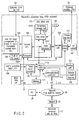
- FIG. 2 is a block diagram for explaining the internal arrangement of recording apparatus (optical disc video recorder, e.g., DVD-VR recorder) 10 according to the embodiment of the present invention.
- This recording apparatus 10 comprises disc drive unit 101 which digitally records a TV broadcast program from built-in TV tuner (terrestrial analog TV broadcast tuner or the like) 103 or analog AV information (a playback signal of an analog video tape, an analog AV output from external tuner 50, or the like) from line AV input 104 on recordable optical disc (DVD-RAM disc, DVD-R disc, or the like) 102, and plays back recorded digital AV information from disc 102.
- DVD-RAM disc recordable optical disc
- DVD-R disc DVD-R disc, or the like
- a component D input (D1 that handles an NTSC color difference input, D2 that handles a progressive color difference input, D3 to D5 that handle Hi-vision color difference inputs, and the like), an S terminal, and/or a coaxial input that receives a composite NTSC video signal may be used.
- Analog AV information (that includes video information, audio information, and other sub information as needed) from built-in TV tuner 103 or line AV input 104 is A/D-converted and MPEG-encoded in encoder unit 105, and is converted into a predetermined recording signal by formatter 105A.
- the converted recording signal is sent to data processor 101C of disc drive unit 101 (audio information may be encoded by linear PCM).
- audio information may be encoded by linear PCM.
- the recording signal of a digital stream sent to data processor 101C is digitally recorded on optical disc 102 loaded to disc drive 101A while using temporary storage unit (large-capacity buffer memory) 101B as needed.
- Decoder unit 106 Upon playback, digital information played back from disc 102 by disc drive 101A is sent to decoder unit 106 via data processor 101C.
- Decoder unit 106 incorporates video and audio MPEG decoders (and a linear PCM decoder as needed), and outputs a decoded digital AV signal to video mixer 116.
- Video mixer 116 superimposes on-screen display (OSD) information instructed by, e.g., main MPU 110, on a video picture output from decoder 106 using frame memory 117. A window display of the electronic program guide can be made using this OSD information.
- OSD on-screen display
- the video picture on which the OSD information is superimposed and an audio signal for this picture are D/A-converted into an analog signal, which is output to external monitor (or external TV) 60 via AV output (D terminal, coaxial terminal, or the like) (digital AV information before D/A conversion may be output via the IEEE1394 I/F).
- Recording apparatus 10 shown in FIG. 2 also comprises input unit 108 that accepts user's operations, and remote controller receiver 120 which accepts user's remote controller operations.
- These user's operation commands are sent to main MPU 110, which executes processes corresponding to user's command (recording command, playback command, recording scheduling command, input switch command, channel switch command of the built-in TV tuner, and the like) using memory 111 in response to these commands.
- Processing states corresponding to these user's commands are displayed on display unit (fluorescent tube or liquid crystal display) 112 as needed, and/or are displayed as OSD data via video mixer 116.
- Display unit 112 and/or OSD can display operation information of, e.g., a recording scheduling process and the like under the control of main MPU 110.
- Recording apparatus 10 shown in FIG. 2 further comprises timer microcomputer (timer MPU) 109, which is connected to main MPU 110 to support scheduled recordings using EPG and the like, and communication controller 113 and I/F 114, which are used to establish connection to the Internet via network router 30.
- Network router 30, modem 32, and PC 20 in FIG. 2 correspond to those with the same reference numerals in the arrangement shown in FIG. 1.
- "Electronic program site 40 on Web" shown in FIG. 2 is one example of information that can be obtained from the Internet shown in FIG. 1.
- Timer MPU 109 saves and registers recording schedule information (EPG information) on memory 111, and executes a recording scheduling process according to the recording schedule information.
- MPU 110 serves as a main controller of recording apparatus 10, and has a function of acquiring and managing recording schedule information (to be described later).
- Memory 111 is a shared memory which is accessed by both timer MPU 109 and MPU 110, and mainly saves (registers) recording schedule information (EPG information).
- Communication controller 113 is connected to the Internet or the like via network router 30 and communicates (exchanges) various kinds of information.
- PC 20 may be a portable information terminal (or a personal digital assistant PDA) that can establish connection to the Internet or a portable phone having an Internet connection function.
- Electronic program site 40 on the Web corresponds to an information service site that provides EPG information (recording schedule information) via the Internet.
- firmware to be executed by timer MPU 109 is written in its internal ROM (not shown), and firmware to be executed by main MPU 110 is written in its internal ROM (not shown).
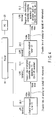
- FIG. 3 is a block diagram for explaining the internal arrangement of the external tuner (e.g., a set-top box which receives satellite and/or terrestrial digital broadcast, or a tuner section of a digital TV that incorporates a tuner which receives satellite and/or terrestrial digital broadcast) according to the embodiment of the present invention.
- the external tuner e.g., a set-top box which receives satellite and/or terrestrial digital broadcast, or a tuner section of a digital TV that incorporates a tuner which receives satellite and/or terrestrial digital broadcast
- set-top box STB which receives satellite and/or terrestrial digital broadcast will be exemplified as the external tuner.
- Tuner unit 502 in the external tuner (STB) in FIG. 3 is connected to satellite antenna (and dedicated UHF antenna for terrestrial digital broadcast) 500.
- Tuner unit 502 has an arrangement for receiving satellite digital broadcast (BS/CS digital broadcast) and/or terrestrial digital broadcast.
- a digital broadcast stream (MPEG-TS or the like) received by tuner unit 502 is sent to decoder 504.
- digital information to be externally output is sent to IEEE1394 I/F 506 as a digital stream.
- information to be externally output after analog conversion is MPEG-decoded by decoder 504, and is then sent to video mixer 508.
- Video mixer 508 superimposes on-screen information (menu dialog or the like) from control MPU 520 on the MPEG-decoded broadcast picture using frame memory 510 as needed, and sends it to AV output unit 512.
- AV output unit 512 A/D-converts the received broadcast picture (including on-screen information as needed), and externally outputs digital information in a predetermined signal format (e.g., a component D1 output, Y/C-separated S output, or composite coaxial output). Furthermore, AV output unit 512 outputs audio information (MPEG MP2 audio information or AAC 5.1ch multi-audio) decoded by decoder 504 as digital information or analog information after D/A conversion (a signal line of audio information is not shown).
- a predetermined signal format e.g., a component D1 output, Y/C-separated S output, or composite coaxial output.
- audio information MPEG MP2 audio information or AAC 5.1ch multi-audio
- control MPU 520 The operations (power ON/OFF, reception channel switch setup, various kinds of output control of AV information, display control of various setup menus, and the like) of STB 50 in FIG. 3 are controlled by control MPU 520.
- This MPU 520 incorporates a ROM written with control firmware, and a ROM written with various control parameters.
- Memory 522 is connected to control MPU 520 to serve as a work area upon execution of firmware and as a temporary storage unit of various kinds of setup information.
- remote controller receiver 524 for receiving user's operation commands from remote controller 526, timer 530 used to detect time, display unit 528 for displaying the operation or setup state, and network controller 540 and I/F 542 required to establish connection to recording apparatus 10 in FIG. 2 via the network, are connected.
- FIG. 4 is a diagram for explaining the system arrangement when a plurality of recording apparatuses (10-1, 10-2) and a plurality of external tuners (50-1, 50-2) are connected on the network.
- recording apparatus 10-1 is a DVD-VR recorder which has only an analog line input
- an analog video output (composite D1 output + audio output, etc.) of digital broadcast tuner 50-1 is connected to an analog video input (line AV input 104 in FIG. 2) of recording apparatus 10-1.
- recording apparatus 10-2 is a streamer (DVD-SR recorder or D-VHS® recorder, or hard disc streamer) having a digital input
- a digital output (IEEE1394 output, etc.) of the digital broadcast tuner 50-2 is connected to a digital input (IEEE1394 I/F 115 in FIG. 2) of recording apparatus 10-2 via a cable.
- DVD-VR recorder 10-1 which has only a terrestrial analog TV tuner can record BS digital broadcast programs, and streamer 10-2 which does not incorporate any tuner can perform stream recording of terrestrial digital broadcast programs. Furthermore, a case wherein even if recorder 10-1 incorporates a digital broadcast tuner, an AV signal from an external tuner with higher performance than the built-in tuner is to be recorded via a line input, can be coped with.
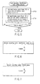
- FIG. 5 is a flow chart for explaining an example of a method of pairing one recording apparatus and one external tuner when one or more recording apparatuses and one or more external tuners are connected on the network.
- FIG. 6 shows an example of an operation dialog (menu dialog) used in each external tuner to select and set the identification name (ID) on the network when one or more recording apparatuses and one or more external tuners are connected on the network.
- FIG. 7 shows an example of a menu dialog used in each recording apparatus to select and set the identification name (ID) of a pairing partner (external tuner to be controlled) on the network when one or more recording apparatuses and one or more external tuners are connected on the network.
- FIG. 5 exemplifies a case wherein the user sets up apparatuses to operate the recording apparatus and external tuner in collaboration with each other.
- a recording apparatus e.g., 10-1 in FIG. 4
- a recording apparatus e.g., 10-1 in FIG. 4
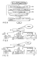
- FIG. 8 is a flow chart for explaining an example of a process for registering a correspondence table between channel information obtained from the electronic program site on the Internet, and channel information of an external tuner in a recording apparatus which forms a pair with that external tuner.
- the user executes a process for registering correspondence between channel CH of external tuner 50 and channel CH of TV program site 40 in recording apparatus 10.
- a channel number and broadcast station name displayed on external tuner 50 using OSD are available.
- the broadcast station name to be displayed is displayed using information transmitted from a broadcast station using a broadcast wave.
- information that allows the user to recognize specific CH in program information of TV program site 40 is a broadcast station name.
- the broadcast station name in this case is displayed on the basis of data that a supervisor of TV program site 40 gets from, e.g., a company that provides TV program data.
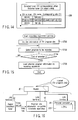
- FIG. 8 A process for generating a correspondence table to this end is the process shown in FIG. 8. This process will be explained below with reference to FIGS. 9 to 11 (which show the flow of information upon determining correspondence between CH information of an external tuner and that of a TV program site) and FIGS. 12 to 14 (which show PC operation dialogs upon determining correspondence between CH information of an external tuner and that of a TV program site on the PC; examples of PC dialogs displayed in correspondence with user's operations).
- the user acquires channel information of external tuner 50 (step ST20).
- the flow of information on the network at that time is as shown in FIG. 10.
- dialog (setup menu dialog) 200 to be displayed on PC 20 at that time is as shown in, e.g., FIG. 12.
- FIG. 12 exemplifies a state wherein channel information "BS102" of external tuner 50 and corresponding channel name "NHK BS2", which are to be set in a correspondence table, are selected (correspondence is not determined yet).
- the user acquires channel information of the TV program site using PC 20 (step ST22).
- the flow of information on the network at that time is as shown in FIG. 9.
- dialog (setup menu dialog) 200 to be displayed on PC 20 at that time is as shown in, e.g., FIG. 13.
- FIG. 13 exemplifies a state wherein channel information ("NHK 2 (BS102)") of TV program site 40, which is to be set in correspondence with the selected channel information ("BS102" and corresponding channel name "NHK BS2”) of external tuner 50, is selected.
- dialog (setup menu dialog) 200 displayed on PC 20 is as shown in, e.g., FIG. 14 (a dialog that reflects correspondence associated with BS102). This generation process is repeated in correspondence with the number of channels to be set in the correspondence table (NO in step ST26).
- step ST26 Upon completion of generation of the correspondence table (YES in step ST26), data of the completed correspondence table is loaded (registered) from PC 20 onto internal memory (a given area of memory 111 in FIG. 2) of recording apparatus 10 (step ST28). The flow of information at that time is as shown in FIG. 11.
- FIG. 15 is a flow chart for explaining an example of a method of selecting a "program to be recorded” from electronic program site 40 on the Internet and registering the selected program information in recording apparatus 10 when recording apparatus 10 and external tuner 50, which are paired, are connected on the network.
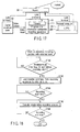
- FIGS. 16 and 17 show the flow of information from when the user searches TV program site 40 for a desired program until he or she registers its recording schedule.
- step ST30 In order to register a program to be recorded from electronic TV program site 40 on the Internet, electronic TV program information is acquired from this site 40 onto PC 20 (step ST30). The flow of information on the network at that time is as shown in FIG. 16. As a result, the electronic TV program guide of that site is displayed on screen 200 of PC 20.
- the user searches for a program to be recorded while browsing program information displayed on screen 200. If the user finds a program to be recorded from that program information, he or she selects a desired program by a simple operation, e.g., by clicking a mouse button of PC 20 (step ST32). This selection operation is repeated in correspondence with the number of desired programs (NO in step ST34). Upon completion of selection (YES in step ST34), the user clicks a "register button" (not shown) on screen 200 of PC 20 using the mouse, thereby loading the selected program information onto memory 111 of recording apparatus 10 (step ST36). The flow of information on the network at that time is as shown in FIG. 17. In this manner, recording information (recording schedule information) selected from electronic TV program site 40 on the Internet is registered in recording apparatus 10.
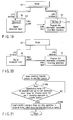
- FIG. 18 is a flow chart for explaining an example of a recording process executed by the recording apparatus, in which program information selected from the electronic program site on the Internet is registered, in collaboration with the external tuner, when the recording apparatus and external tuner, which are paired, are connected on the network.
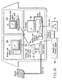
- FIGS. 19 and 20 show the flow of information when recording apparatus 10 and external tuner 50 execute a recording operation in collaboration with each other.
- Recording apparatus 10 has timer MPU 109, as shown in FIG. 2, and external tuner 50 which collaborates with this recording apparatus 10 has timer 530, as shown in FIG. 3. Hence, recording apparatus 10 and external tuner 50 can always detect the current time as long as their own timers are correctly set (although some errors are permitted). Recording apparatus 10 can determine based on the recording start time of the recording information registered in its memory 111 when it must start recording.
- recording apparatus 10 loads a transfer command of AV information to be recorded (step ST42) at a predetermined time (e.g., at a time about 15 seconds before the start time) before the recording start time (YES in step ST40).
- a transfer command of AV information to be recorded (step ST42) at a predetermined time (e.g., at a time about 15 seconds before the start time) before the recording start time (YES in step ST40).
- the flow of information on the network at this time is as shown in FIG. 19.
- information channel information of site 40 has been converted into a corresponding channel number of external tuner 50 via the correspondence table shown in FIG. 14
- recording information recording schedule information
- the MPUs of recording apparatus 10 and external tuner 50 which are paired (matching of their IDs has been detected by the process in FIG. 5), can detect a broadcast channel to be recorded and its recording start time from the program information stored in their memories.
- step ST44 If the recording start time is reached (YES in step ST44), recording apparatus 10 and external tuner 50, which are paired, execute a recording process in collaboration with each other (step ST46). That is, external tuner 50 tunes the designated channel based on the recording information registered from recording apparatus 10 via the network, and outputs a video output of a broadcast program of that channel within the designated time band. This collaborative recording operation continues until the recording end time in the recording schedule information stored in the memories of both recording apparatus 10 and external tuner 50 is reached (NO in step ST48). The flow of AV information to be recorded at that time is as shown in FIG. 20 (line connection from the video output of digital tuner 50 to the video input of recording apparatus 10).
- the recording information is consolidated in recording apparatus 10 until a time immediately before the recording start time. That is, user's operations such as browsing, registration, deletion, and the like of the recording information are done at recording apparatus 10, and the user need not make similar operations for external tuner 50.
- the "predetermined time before recording start" in step ST40 is not limited to the aforementioned time 15 seconds before the start time. This time is merely an example, and a time of 5 seconds or 5 minutes may be set. Since the recording schedule information is to be consolidated on the recording apparatus 10 side, it is not preferable to set this time too early (e.g., several hours or days) before the recording start time. However, when external tuner 50 and/or recording apparatus 10 must be disconnected from the network during a given period that overlaps a scheduled recording time (for example, when the number of hubs of router 30 is limited, and a hub for external tuner 50 and/or recording apparatus 10 must be used for another purpose), the recording schedule information must be transferred from recording apparatus 10 to external tuner 50 before disconnection.
- the predetermined time in step ST40 can be set considerably before the recording start time.
- external tuner 50 can output AV information which is scheduled to be recorded to the line input of recording apparatus 10.
- FIG. 21 is a flow chart for explaining an example of the contents of the process (step ST42) when a transfer command is loaded from the recording apparatus to the external tuner in the recording process shown in FIG. 18.
- a transfer command (a command that instructs to transfer a broadcast program of xxx channel from yyy o'clock to zzz o'clock) based on the recording schedule information is loaded from recording apparatus 10 to external tuner 50, whose identification names match (step ST426).
- FIG. 22 is a flow chart for explaining an example of the collaborative recording process (step ST46) between the external tuner and recording apparatus, which are paired, in the recording process shown in FIG. 18.
- FIG. 23 is a flow chart for explaining the operation for eliminating a process incompatible with maintenance of tuning of a recording channel on the external tuner side.
- step ST460a if a tuning instruction at the external tuner is issued (step ST460a), it is checked if transfer of AV information from external tuner 50 to recording apparatus 10 is in progress at that time. If transfer is in progress (YES in step ST460b), it is determined that the tuning instruction in step ST460a is a "process which is incompatible with maintenance of tuning of the recording channel (a process that may result in a recording failure)", and the process of the tuning instruction is aborted (step ST460c).
- step ST460a if transfer is not in progress (NO in step ST460b), it is determined that the tuning instruction in step ST460a is a "process which is compatible with maintenance of tuning of the recording channel (a process that does not result in a recording failure)", and the process of the tuning instruction is executed (step ST460d).
- Examples of the process which is incompatible with maintenance of tuning of the recording channel (a process that may result in a recording failure) in external tuner 50 during the recording operation period includes an operation for the external tuner main body using remote controller 526 or the like of external tuner 50, an automatic process (e.g., emergency warning broadcast in BS digital broadcast) designated from a broadcast wave, and the like.
- an automatic process e.g., emergency warning broadcast in BS digital broadcast
- AV information of a broadcast program to be recorded begins to be transferred from external tuner 50 to recording apparatus 10 while tuning of the recording channel is maintained during recording (during transfer of AV information to recording apparatus 10) by the process in FIG. 23 (step ST462 in FIG. 22).
- Recording apparatus 10 then begins to record the transferred AV information (line input) (step ST464 in FIG. 22). After that, the control returns to step ST48 in FIG. 18, and the collaborative recording process between external tuner 50 that "maintains tuning of the recording channel" and recording apparatus 10 is maintained until the recording end time in the schedule information set in their memories is reached.
- FIG. 24 is a diagram for explaining the system arrangement in which a recording method using a network (wired LAN) according to another embodiment of the present invention is used.
- wireless LAN cards and wireless LAN adapters (10x, 50x) are used in combination in place of a network built by connecting cables to router 30, thus building the same network as in FIG. 1 as a wireless network.
- the collaborative recording process shown in FIG. 18 can be realized between recording apparatus 10 which is set at the first floor of a given house and external tuner 50 which is set at the second floor.
- the present invention is not limited to the aforementioned embodiments, and various modifications may be made without departing from the scope of the invention when it is practiced.
- the embodiment shown in FIG. 1 and the like uses Ethernet® as the network connection between recording apparatus 10 and external tuner 50.
- this network connection may use other lines as long as it can send a recording channel, recording start time, recording end time, transfer command of a program to be recorded from recording apparatus 10 to external tuner 50.
- network connection from recording apparatus 10 to external tuner 50 may use IEEE1394, USB (Universal Serial Bus), RS232C, and the like.
- a transfer command to be sent from recording apparatus 10 to external tuner 50 is not limited to the one (e.g., "recording schedule") which is sent immediately before the recording start time.
- This command can be output from recording apparatus 10 to external tuner 50 when the user wants to start recording right now (on-time recording).
- the respective embodiments may be combined as needed as long as such combinations are possible, and combined effects can be obtained in such case.
- the embodiments include inventions of various stages, and various inventions can be extracted by appropriately combining a plurality of disclosed required constituent elements. For example, even when one or a plurality of required constituent elements are omitted from all required constituent elements described in the embodiment, an arrangement from which the required constituent elements are omitted can be extracted as an invention as long as at least one of the effects of the present invention or the effects obtained upon practicing the present invention can be obtained.
- a scheduled recording process using the external tuner can be made by simple user's operations (e.g., a scheduling operation for only the recording apparatus using an electronic program guide on the Internet; the need for an independent scheduling operation for the external tuner can be omitted).
Landscapes
- Engineering & Computer Science (AREA)
- Signal Processing (AREA)
- Multimedia (AREA)
- Databases & Information Systems (AREA)
- Automation & Control Theory (AREA)
- General Engineering & Computer Science (AREA)
- Business, Economics & Management (AREA)
- Finance (AREA)
- Strategic Management (AREA)
- Computer Networks & Wireless Communication (AREA)
- Human Computer Interaction (AREA)
- Television Signal Processing For Recording (AREA)
- Two-Way Televisions, Distribution Of Moving Picture Or The Like (AREA)
Applications Claiming Priority (2)
| Application Number | Priority Date | Filing Date | Title |
|---|---|---|---|
| JP2003155939 | 2003-05-30 | ||
| JP2003155939A JP2004363649A (ja) | 2003-05-30 | 2003-05-30 | ネットワークを利用した録画方法および録画装置 |
Publications (1)
| Publication Number | Publication Date |
|---|---|
| EP1482728A2 true EP1482728A2 (de) | 2004-12-01 |
Family
ID=33128339
Family Applications (1)
| Application Number | Title | Priority Date | Filing Date |
|---|---|---|---|
| EP04006244A Withdrawn EP1482728A2 (de) | 2003-05-30 | 2004-03-16 | Netzwerk benutzende Aufnahmeverfahren und Aufnahmesystem. |
Country Status (3)
| Country | Link |
|---|---|
| US (1) | US20040240858A1 (de) |
| EP (1) | EP1482728A2 (de) |
| JP (1) | JP2004363649A (de) |
Cited By (2)
| Publication number | Priority date | Publication date | Assignee | Title |
|---|---|---|---|---|
| EP2051520A4 (de) * | 2006-07-20 | 2010-07-07 | Sharp Kk | Digitaler broadcast-empfänger |
| EP2192774A4 (de) * | 2007-09-28 | 2011-05-18 | Sony Corp | Anzeigevorrichtung, datenübertragungsverfahren für die anzeigevorrichtung, übertragungsvorrichtung sowie datenempfangsverfahren für die übertragungsvorrichtung |
Families Citing this family (4)
| Publication number | Priority date | Publication date | Assignee | Title |
|---|---|---|---|---|
| US7440682B2 (en) * | 2004-04-28 | 2008-10-21 | Fujifilm Corporation | Electronic-album displaying system, electronic-album displaying method, remote controller, machine readable medium storing remote control program, schedule generating device, and machine readable medium storing schedule generating program |
| JP2007096972A (ja) * | 2005-09-29 | 2007-04-12 | Toshiba Corp | 信号受信装置およびその受信信号管理方法ならびに受信信号管理プログラム |
| US20150067099A1 (en) * | 2013-08-30 | 2015-03-05 | U-Me Holdings LLC | Transferring user settings from one device to another |
| US12028576B1 (en) * | 2019-02-28 | 2024-07-02 | Amazon Technologies, Inc. | Remote scheduling of recorded content for digital video recorders |
Family Cites Families (6)
| Publication number | Priority date | Publication date | Assignee | Title |
|---|---|---|---|---|
| US5123046A (en) * | 1990-11-05 | 1992-06-16 | Smart Vcr Limited Partnership | Vcr with cable tuner control |
| US5515173A (en) * | 1993-03-05 | 1996-05-07 | Gemstar Developement Corporation | System and method for automatically recording television programs in television systems with tuners external to video recorders |
| US5661526A (en) * | 1993-08-25 | 1997-08-26 | Sony Corporation | Broadcast signal receiver and tape recorder and, method of detecting additional information channel |
| US7013339B2 (en) * | 1998-07-06 | 2006-03-14 | Sony Corporation | Method to control a network device in a network comprising several devices |
| JP2001243676A (ja) * | 2000-02-29 | 2001-09-07 | Sony Corp | 情報処理装置及び方法、媒体 |
| JP4280960B2 (ja) * | 2000-10-24 | 2009-06-17 | ソニー株式会社 | 情報処理装置および方法、並びにプログラム格納媒体 |
-
2003
- 2003-05-30 JP JP2003155939A patent/JP2004363649A/ja not_active Withdrawn
-
2004
- 2004-03-16 EP EP04006244A patent/EP1482728A2/de not_active Withdrawn
- 2004-04-27 US US10/832,378 patent/US20040240858A1/en not_active Abandoned
Cited By (3)
| Publication number | Priority date | Publication date | Assignee | Title |
|---|---|---|---|---|
| EP2051520A4 (de) * | 2006-07-20 | 2010-07-07 | Sharp Kk | Digitaler broadcast-empfänger |
| US8285122B2 (en) | 2006-07-20 | 2012-10-09 | Sharp Kabushiki Kaisha | Digital broadcast receiver |
| EP2192774A4 (de) * | 2007-09-28 | 2011-05-18 | Sony Corp | Anzeigevorrichtung, datenübertragungsverfahren für die anzeigevorrichtung, übertragungsvorrichtung sowie datenempfangsverfahren für die übertragungsvorrichtung |
Also Published As
| Publication number | Publication date |
|---|---|
| JP2004363649A (ja) | 2004-12-24 |
| US20040240858A1 (en) | 2004-12-02 |
Similar Documents
| Publication | Publication Date | Title |
|---|---|---|
| US8607280B2 (en) | Resource and capability borrowing | |
| US8306402B2 (en) | Time shift view/listening system, display device, and time shift view/listening method | |
| EP1962508A2 (de) | Netzwerksystem, Kontrollvorrichtung, Aufzeichnungsvorrichtung, Diensteserver, Verfahren zur Erfassung des Ressourcenstatus der Aufzeichnungsvorrichtung und Computerprogramm | |
| US20100037269A1 (en) | Recording system, receiving apparatus, recording apparatus, recording control method, and program | |
| EP1482728A2 (de) | Netzwerk benutzende Aufnahmeverfahren und Aufnahmesystem. | |
| US8429689B2 (en) | Program data processing method and apparatus | |
| US7716696B2 (en) | Television receiver, information processing method and program | |
| JP3882799B2 (ja) | 番組データ記録方法及び装置 | |
| JP4474966B2 (ja) | 映像記録装置および記録制御方法 | |
| EP1176822A2 (de) | Signalausgangsvorrichtung und -verfahren | |
| US8689262B2 (en) | Broadcast receiving device | |
| US20090007183A1 (en) | Video recording apparatus and broadcast receiving apparatus | |
| JP3720347B2 (ja) | 表示装置、センタ装置、映像表示システム、表示装置の制御方法、センタ装置の制御方法、表示装置制御プログラム、センタ装置制御プログラム、および該プログラムを記録した記録媒体 | |
| US7386220B2 (en) | Apparatus and method for controlling recording operation for video cassette recorder having digital tuner | |
| EP2884693A2 (de) | Rundfunkempfangsvorrichtung und Rundfunkempfangsverfahren | |
| JP2005094498A (ja) | 番組データ記録方法及び装置 | |
| JP2000216737A (ja) | ディジタル放送受信装置及びその制御方法 | |
| JP2005123905A (ja) | 録画装置 | |
| JP2008136136A (ja) | データ通信装置、装置一覧表示方法および装置一覧表示制御プログラム | |
| JP2004248056A (ja) | コンテンツ記録装置およびコンテンツ再生装置ならびにコンテンツ記録プログラムおよびコンテンツ再生プログラム | |
| EP1922869A2 (de) | Verfahren zum routen eines audio-/videosignals von dem internen tuner eines fernsehers zu einer abgesetzten einrichtung | |
| JP4257174B2 (ja) | 記録装置及び予約方法 | |
| JP2007336204A (ja) | 情報記録装置および情報記録用通信装置 | |
| EP2403231A1 (de) | Verfahren zur Einstellung der Reservierung in einem Rundfunkempfänger | |
| JP2000004434A (ja) | ディジタル放送受信装置及びその制御方法 |
Legal Events
| Date | Code | Title | Description |
|---|---|---|---|
| PUAI | Public reference made under article 153(3) epc to a published international application that has entered the european phase |
Free format text: ORIGINAL CODE: 0009012 |
|
| 17P | Request for examination filed |
Effective date: 20040316 |
|
| AK | Designated contracting states |
Kind code of ref document: A2 Designated state(s): AT BE BG CH CY CZ DE DK EE ES FI FR GB GR HU IE IT LI LU MC NL PL PT RO SE SI SK TR |
|
| AX | Request for extension of the european patent |
Extension state: AL LT LV MK |
|
| STAA | Information on the status of an ep patent application or granted ep patent |
Free format text: STATUS: THE APPLICATION HAS BEEN WITHDRAWN |
|
| 18W | Application withdrawn |
Effective date: 20080111 |