EP1483014B1 - Procede de controle du fonctionnement d'un element d'interruption d'ecoulement et d'un systeme d'arret d'ecoulement, destine a un circuit de fluide extracorporel - Google Patents
Procede de controle du fonctionnement d'un element d'interruption d'ecoulement et d'un systeme d'arret d'ecoulement, destine a un circuit de fluide extracorporel Download PDFInfo
- Publication number
- EP1483014B1 EP1483014B1 EP03742625A EP03742625A EP1483014B1 EP 1483014 B1 EP1483014 B1 EP 1483014B1 EP 03742625 A EP03742625 A EP 03742625A EP 03742625 A EP03742625 A EP 03742625A EP 1483014 B1 EP1483014 B1 EP 1483014B1
- Authority
- EP
- European Patent Office
- Prior art keywords
- cut
- movable part
- parameter
- monitoring unit
- acceptability
- Prior art date
- Legal status (The legal status is an assumption and is not a legal conclusion. Google has not performed a legal analysis and makes no representation as to the accuracy of the status listed.)
- Expired - Lifetime
Links
- 238000012544 monitoring process Methods 0.000 title claims abstract description 64
- 238000000034 method Methods 0.000 title claims abstract description 30
- 239000012530 fluid Substances 0.000 title claims abstract description 25
- 239000008280 blood Substances 0.000 claims abstract description 42
- 210000004369 blood Anatomy 0.000 claims abstract description 42
- 230000033001 locomotion Effects 0.000 claims abstract description 30
- 238000011282 treatment Methods 0.000 claims abstract description 18
- 230000006870 function Effects 0.000 claims description 23
- 238000012937 correction Methods 0.000 claims description 8
- 230000001133 acceleration Effects 0.000 claims description 7
- 230000004044 response Effects 0.000 claims description 5
- 239000012528 membrane Substances 0.000 claims description 3
- 230000003287 optical effect Effects 0.000 claims description 3
- 230000003213 activating effect Effects 0.000 claims description 2
- 238000013459 approach Methods 0.000 claims description 2
- 238000004891 communication Methods 0.000 claims description 2
- 238000001514 detection method Methods 0.000 claims description 2
- 230000009471 action Effects 0.000 description 6
- 239000007788 liquid Substances 0.000 description 5
- 230000006835 compression Effects 0.000 description 4
- 238000007906 compression Methods 0.000 description 4
- 238000002616 plasmapheresis Methods 0.000 description 4
- 230000007704 transition Effects 0.000 description 4
- 210000000748 cardiovascular system Anatomy 0.000 description 3
- 238000000502 dialysis Methods 0.000 description 3
- 238000001631 haemodialysis Methods 0.000 description 3
- 238000002615 hemofiltration Methods 0.000 description 3
- 238000011144 upstream manufacturing Methods 0.000 description 3
- 230000007257 malfunction Effects 0.000 description 2
- 239000002245 particle Substances 0.000 description 2
- 238000000108 ultra-filtration Methods 0.000 description 2
- 230000002792 vascular Effects 0.000 description 2
- 208000001647 Renal Insufficiency Diseases 0.000 description 1
- 230000008901 benefit Effects 0.000 description 1
- 230000015572 biosynthetic process Effects 0.000 description 1
- 238000010276 construction Methods 0.000 description 1
- 238000013461 design Methods 0.000 description 1
- 230000006866 deterioration Effects 0.000 description 1
- 238000010586 diagram Methods 0.000 description 1
- 230000000694 effects Effects 0.000 description 1
- 201000006370 kidney failure Diseases 0.000 description 1
- 238000004519 manufacturing process Methods 0.000 description 1
- 239000000463 material Substances 0.000 description 1
- 230000000737 periodic effect Effects 0.000 description 1
- 230000002572 peristaltic effect Effects 0.000 description 1
- 230000000750 progressive effect Effects 0.000 description 1
- 230000001902 propagating effect Effects 0.000 description 1
- 230000011664 signaling Effects 0.000 description 1
Images
Classifications
-
- A—HUMAN NECESSITIES
- A61—MEDICAL OR VETERINARY SCIENCE; HYGIENE
- A61M—DEVICES FOR INTRODUCING MEDIA INTO, OR ONTO, THE BODY; DEVICES FOR TRANSDUCING BODY MEDIA OR FOR TAKING MEDIA FROM THE BODY; DEVICES FOR PRODUCING OR ENDING SLEEP OR STUPOR
- A61M39/00—Tubes, tube connectors, tube couplings, valves, access sites or the like, specially adapted for medical use
- A61M39/22—Valves or arrangement of valves
- A61M39/28—Clamping means for squeezing flexible tubes, e.g. roller clamps
- A61M39/281—Automatic tube cut-off devices, e.g. squeezing tube on detection of air
-
- A—HUMAN NECESSITIES
- A61—MEDICAL OR VETERINARY SCIENCE; HYGIENE
- A61M—DEVICES FOR INTRODUCING MEDIA INTO, OR ONTO, THE BODY; DEVICES FOR TRANSDUCING BODY MEDIA OR FOR TAKING MEDIA FROM THE BODY; DEVICES FOR PRODUCING OR ENDING SLEEP OR STUPOR
- A61M1/00—Suction or pumping devices for medical purposes; Devices for carrying-off, for treatment of, or for carrying-over, body-liquids; Drainage systems
- A61M1/14—Dialysis systems; Artificial kidneys; Blood oxygenators ; Reciprocating systems for treatment of body fluids, e.g. single needle systems for hemofiltration or pheresis
- A61M1/16—Dialysis systems; Artificial kidneys; Blood oxygenators ; Reciprocating systems for treatment of body fluids, e.g. single needle systems for hemofiltration or pheresis with membranes
-
- A—HUMAN NECESSITIES
- A61—MEDICAL OR VETERINARY SCIENCE; HYGIENE
- A61M—DEVICES FOR INTRODUCING MEDIA INTO, OR ONTO, THE BODY; DEVICES FOR TRANSDUCING BODY MEDIA OR FOR TAKING MEDIA FROM THE BODY; DEVICES FOR PRODUCING OR ENDING SLEEP OR STUPOR
- A61M2205/00—General characteristics of the apparatus
- A61M2205/18—General characteristics of the apparatus with alarm
-
- A—HUMAN NECESSITIES
- A61—MEDICAL OR VETERINARY SCIENCE; HYGIENE
- A61M—DEVICES FOR INTRODUCING MEDIA INTO, OR ONTO, THE BODY; DEVICES FOR TRANSDUCING BODY MEDIA OR FOR TAKING MEDIA FROM THE BODY; DEVICES FOR PRODUCING OR ENDING SLEEP OR STUPOR
- A61M2205/00—General characteristics of the apparatus
- A61M2205/50—General characteristics of the apparatus with microprocessors or computers
-
- A—HUMAN NECESSITIES
- A61—MEDICAL OR VETERINARY SCIENCE; HYGIENE
- A61M—DEVICES FOR INTRODUCING MEDIA INTO, OR ONTO, THE BODY; DEVICES FOR TRANSDUCING BODY MEDIA OR FOR TAKING MEDIA FROM THE BODY; DEVICES FOR PRODUCING OR ENDING SLEEP OR STUPOR
- A61M2205/00—General characteristics of the apparatus
- A61M2205/70—General characteristics of the apparatus with testing or calibration facilities
- A61M2205/702—General characteristics of the apparatus with testing or calibration facilities automatically during use
Definitions
- the present invention relates to a method of monitoring the operationality of a flow cut-off member for an extracorporeal fluid circuit; the invention also relates to a flow arresting system for an extracorporeal fluid circuit.
- the invention is of application in ensuring the correct functioning of a flow cut-off member operating on a blood return line to the patient in an extracorporeal circuit connected to a blood treatment appliance.
- the invention can also be applied to carrying out an operation on the abovementioned flow cut-off member if it is found to be malfunctioning.
- appliances for treating blood in an extracorporeal circuit such as appliances for treating renal insufficiency by haemodialysis, haemofiltration, or haemodiafiltration, plasmapheresis appliances, etc, use an extracorporeal circuit to carry the blood taken from a patient to a blood treatment unit.
- This unit normally consists of a containment body defining at least one first chamber, for incoming blood, and at least one second chamber, designed to receive the unwanted particles and/or excess fluid present in the blood (or the plasma in the case of plasmapheresis).
- the two chambers are separated from each other by a semipermeable membrane.
- the first chamber of the treatment unit is then connected, downstream with respect to the direction of movement of the blood, to a return branch or line carrying the blood back to the patient.
- the terminal portion of the blood return line is normally fitted with an access member, such as a needle or other device, for connecting the extracorporeal circuit to the patient's vascular system.
- an access member such as a needle or other device
- a flow interruption member generally a clamp or pinch valve, capable of closing upon a length of tube of the blood return line to the patient.
- the pinch value has at least one movable portion designed to move between an open condition, in which flow is allowed along the tubing, and a closed condition, in which the movable part of the valve moves towards its fixed part, compressing the tube and therefore cutting off the flow of fluid through the tube.
- the pinch valve acts as the final safety device, capable of cutting off the flow of blood to the patient immediately any malfunction or any danger to the patient arises.
- the pinch valve may be controlled by a monitoring unit communicating with sensors or transducers that pass to this monitoring unit signals about potentially dangerous situations.
- the monitoring unit may be linked to an air bubble detection unit active on the extracorporeal circuit upstream of the pinch valve: in the event of air bubbles large enough to create a situation of potential danger to the patient, the monitoring unit closes the clamp, preventing the bubble from getting into the vascular system of the patient.
- the pinch valve In order to be able to ensure operationality of the pinch valve, the latter is typically equipped with a position sensor for detecting when the movable part has reached a predetermined position (taken to correspond to closure of the tube) relative to the fixed part, upon which it sends a corresponding signal to the monitoring unit.
- the position sensor checks that, in flow cut-off conditions, the movable part of the clamp is separated from the lower fixed part by a predefined distance, approximately corresponding to the total thickness of the walls of the tube when compressed by the valve.
- the position sensors connected to the cut-off systems described above are only able to supply an on-off type indication, i.e. they are only able to decide whether the movable part has reached a predetermined position of closure relative to the fixed part and possibly to recognize the presence or absence of a tube in the correct position inside the clamp.
- devices with a pinch valve and position sensor cannot give information about how the valve carries out the transition to closure or relate the transition to closure of the valve to the manner in which the dangerous event is propagating towards the zone of access to the patient.
- the ideal solution would be to succeed in completely cutting off the flow of blood to the patient before the volume of blood present between the section containing the bubble and the patient access point is completely exhausted.
- the clamp does not work fast enough, there is a risk of the dangerous event (in this case the air bubble) being transferred into the cardiovascular system of the patient.
- the position sensor is designed to detect when the movable part of the clamp reaches a predetermined position; this position corresponds to a distance between the cooperating parts of the valves at which, theoretically, the flow through the tube would be cut off, assuming that the maximum wall thickness of the tube is in a tolerance range judged to be acceptable.
- This design decision avoids undesirable situations of false alarms but does not ensure that actual flow cut-off is monitored, particularly when the tube has walls of the minimum thickness even if within a tolerance judged to be acceptable.
- the effects described above can be aggravated if the pinch valve is operated repeatedly on the same length of tube (as occurs for example in single-needle treatments), causing deterioration to the material and/or permanent deformations thereof.
- US-A-6 012 342 discloses a plunger assembly for occluding the flow of fluid through a flexible tube, the assembly having sensor means for measuring the force applied by a plunger tip on the flexible tube.
- a flow cut-off member for example a clamp
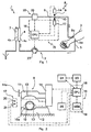
- an extracorporeal blood-treatment appliance is indicated as a whole by the number 1.
- the appliance 1 may be, for example, a haemodialysis and/or haemofiltration and/or haemodiafiltration and/or ultrafiltration and/or plasmapheresis appliance.
- the appliance 1 comprises an extracorporeal circuit 2 designed to carry blood from a patient 3 to a blood-treatment unit 4 and then return the blood, suitably treated, to a return zone where the blood is returned to the patient.
- the extracorporeal circuit typically has a first access member 5a in fluid communication with a blood collecting line 5 leading to an entry zone where the blood enters the treatment unit 4.
- the extracorporeal circuit also includes a blood return line 6 leading to a second access member 6a connecting to the patient's cardiovascular system for return of the blood to the patient.
- a single access member may be connected alternately to the blood collecting line and then to the blood return line.
- the blood treatment unit comprises a containment body defining at least two chambers 4a, 4b separated from each other by a semipermeable membrane 7.
- the first chamber 4a receives blood to be treated from the extracorporeal circuit briefly described above.
- the second chamber is designed to receive unwanted particles and/or excess liquid for removal from the patient's blood.
- the treatment unit 4 also includes a plasma filter.
- the appliance 1 comprises a system 8 for arresting the flow of fluid, in this case blood, which will be described in detail below.
- the system 8 acts on at least one flow cut-off member 9 operating on a length of deformable tubing 10 of the extracorporeal circuit; in particular, the flow cut-off member operates between an open condition, in which it allows the fluid to pass through, and at least one closed condition, in which it prevents the fluid passing along the said length of tube.
- the cut-off member is positioned on the return line 6 taking the blood back to the patient, close to and upstream of the second access member 6a.
- the cut-off member comprises at least one movable portion 11 designed to move towards and away from a fixed portion 12.
- the movable portion and the fixed portion together define a housing seat 13 in which the abovementioned length of tubing 10 sits. Because of the radial deformability of the length of tubing 10, the movement of the movable portion towards the fixed portion of the cut-off member causes progressive compression of the length of tubing, which therefore changes from an open condition, illustrated in Figure 2 , to a closed condition in which the side walls of the tube come together and cut off the flow of fluid. Movement of the movable member as described above is provided by an actuator 14 connected to the cut-off member 14.
- the actuator 14 may be of any type capable of bringing about a closing movement of the movable portion towards the fixed portion; in particular, a hydraulic, pneumatic, electric, electromagnetic, mechanical or any other type of actuator may be used.
- the actuator 14 acts under the control of a monitoring unit 15 connected to the said actuator.
- the monitoring unit 15 of the system illustrated comprises a control unit 16, and means 17 for detecting a sequence of placings of the said movable portion in successive positions, sending corresponding signals to the said monitoring unit.
- the monitoring unit comprises at least one microprocessor block 18, or CPU, and a memory 19 for the CPU.
- the detector means 17 meanwhile comprise one or more position sensors. In the example illustrated, there are two position sensors 20, 21 capable of detecting when the movable part 11 reaches two corresponding positions spaced apart from each other.
- the position sensors may for example be optical sights designed to send corresponding consent signals to the CPU 18 for the movement of the said movable portion 11.
- the monitoring unit is also connected to a user interface 22 comprising an output device 23, such as a video display or the like, and an input device 24 comprising data reading means and/or a keyboard.
- a user interface 22 comprising an output device 23, such as a video display or the like, and an input device 24 comprising data reading means and/or a keyboard.
- the system 8 behaves as described below.
- the monitoring unit 15 sends a signal to the actuator to close the cut-off member as a safety function to prevent the event that has been judged to be dangerous from reaching the patient's cardiovascular system.
- the system 8 acts whenever a situation judged to be dangerous is detected.
- the monitoring parameters may be, for example, the size of air bubbles that may be present in the blood, the temperature of the blood and/or the temperature of the dialysis liquid, the pH of the dialysis liquid, the pressure of the blood and/or of the dialysis liquid, etc.
- the sensor means comprise an air bubble detector 26 connected to the extracorporeal circuit, on line 6.
- the system 8 checks that the cut-off member is working properly when it closes: in this case the monitoring unit 15 implements a method of monitoring the cut-off member for correct operation.
- the system 8, or more precisely the monitoring unit 15, runs a check on the operationality of the cut-off member whenever:
- the monitoring unit 15 is capable of sending a signal to the said actuator 14 to move the movable portion (in the directions identified by the arrow 14a) of the cut-off member between a rest position, which corresponds to the open condition of the cut-off member and hence the passage of fluid through the said length of tubing, and a working condition, in which the movable portion acts to compress the portion of tube 10 to cut off the flow.
- the movable portion is typically at a distance from the surface 10a of the tube 10 and comes into contact with the latter during the movement towards the closed condition.
- the monitoring unit 15 is also responsible for associating with the movable portion 11 at least one dynamic parameter p capable of providing an at least partial indication of the condition of motion of the movable portion during its movement from the rest position to the working position. It should be noted that a single dynamic parameter may be used, or a plurality of different dynamic parameters.
- the monitoring unit 15 therefore determines a value V assumed by the said dynamic parameter or parameters when the movable part passes through a first position which the movable part can adopt during movement from the rest condition to the working condition.
- the monitoring unit will assess an average speed value assumed by the movable part in a neighbourhood of the said first position; alternatively, if the dynamic parameter is a time interval, the monitoring unit will determine the time taken by the movable part 11 to move for example from the rest position to the said first position or, alternatively, the time interval taken by the movable part 11 to move from the first position to a second position at a distance from and subsequent to the first position.
- the monitoring unit checks that this value satisfies a predetermined criterion of acceptability.
- a predetermined criterion of acceptability In other words, still referring by way of example to the case in which the parameter is speed, the monitoring unit compares the average speed of the movable portion at a predetermined first position with a criterion of acceptability.
- This criterion of acceptability may be of predetermined type, such as a minimum speed capable of closing the cut-off member quickly enough.
- the criterion of acceptability may be calculated by the monitoring unit as a function of other factors, for example as a function of:
- the first position in which the value assumed by the abovementioned dynamic parameter is determined is a position preferably intermediate between the rest position of the movable part and the working position of the same movable part.
- the first position is intermediate between the ideal working position (complete closure of the tubing 10 with tube of exactly nominal dimensions) and a position of initial contact between the movable portion and the outer surface of the length of tubing.
- the dynamic parameter is designed to describe a condition of motion of the movable portion.
- this parameter is selected from the group comprising the following dynamic parameters:
- the monitoring unit calculates the value of the said parameter p as the time dT (or as a function of the time dT) taken by the movable part to move from the first position to a second position at a distance from the first position.
- this time interval is compared with the criterion of acceptability.
- the time interval may be determined and, therefore, a function proportional to this time interval is calculated in order to then compare it with a criterion of acceptability.
- the monitoring unit arranges for calculation of an average speed assumed by the movable portion in a neighbourhood of the said first position in order to then compare it with the said criterion of acceptability.
- the dynamic parameter is an acceleration or a function of the acceleration of the movable portion (resulting from the forces acting on the movable portion)
- the monitoring unit arranges for calculation of an average acceleration of the movable portion in a neighbourhood of the said position.
- the parameter p or the parameters pi can be determined by analogue sensors that output a continuous signal proportional to the instantaneous value of the parameter.
- the monitoring unit arranges for a comparison between the analogue profile of the parameter p with a criterion of acceptability.
- the monitoring unit associates one, two or more parameters with the movable portion, each parameter being designed to give different dynamic information about the motion of the movable portion as it advances towards the fixed portion.
- the monitoring unit is designed to carry out, for each dynamic parameter, a plurality of phases of determining values Vi assumed by that dynamic parameter at successive predetermined positions assumed by the movable part during its movement. Each value of the parameter in successive positions is however determined essentially as described above.
- the monitoring unit can initiate an alarm signalling procedure and/or a corrective procedure (control).
- the appliance 1 is provided with a user interface 22 equipped with a display by means of which the monitoring unit can send an optical or acoustic signal about the alarm condition.
- the monitoring unit can also, depending on the situation, coordinate stoppage of the treatment which the appliance 1 is performing should the abovementioned alarm condition occur.
- the monitoring unit is also capable of activating a correction phase whereby the monitoring unit intervenes on the actuator 14 to modify its action on the movable portion of the cut-off member, in the light of the difference between the value of the dynamic parameter and a limit value judged to be acceptable for that parameter.
- the monitoring unit activates the actuator member in such a way as to increase or reduce the closing speed and/or force of the movable part.
- the monitoring unit may act on means 27, such as a peristaltic pump, designed to set up a flow of liquid within the extracorporeal circuit, in such a way as to vary the rate of the said flow.
- means 27, such as a peristaltic pump designed to set up a flow of liquid within the extracorporeal circuit, in such a way as to vary the rate of the said flow.
- the actuator can be used to increase its speed, and the pump 27 connected to the extracorporeal circuit can be used simultaneously or alternatively to slow down the rate of flow of fluid through the circuit tubing.
Landscapes
- Health & Medical Sciences (AREA)
- Heart & Thoracic Surgery (AREA)
- Hematology (AREA)
- Engineering & Computer Science (AREA)
- Anesthesiology (AREA)
- Biomedical Technology (AREA)
- Pulmonology (AREA)
- Life Sciences & Earth Sciences (AREA)
- Animal Behavior & Ethology (AREA)
- General Health & Medical Sciences (AREA)
- Public Health (AREA)
- Veterinary Medicine (AREA)
- External Artificial Organs (AREA)
- Flow Control (AREA)
- Examining Or Testing Airtightness (AREA)
Claims (36)
- Méthode pour contrôler l'opérationnalité d'un élément d'arrêt du flux d'un fluide à travers un circuit extracorporel (2),
ledit circuit (2) ayant au moins une première portion de tuyau déformable (10) sur laquelle agit au moins un élément d'arrêt du flux (9) ayant au moins une partie mobile (11) pouvant être actionnée entre une condition ouverte, dans laquelle elle permet le passage du fluide, et au moins une condition fermée, dans laquelle elle empêche le passage du fluide à travers ladite portion de tuyau (10),
ladite méthode comprenant les étapes suivantes:- déplacer la partie mobile (11) de l'élément d'arrêt (9) de ladite condition ouverte à ladite condition fermée;- associer au moins un paramètre dynamique à un mouvement de ladite partie mobile (11);- déterminer une valeur dudit au moins un paramètre dynamique lié à ladite partie mobile (11) au moins pendant ledit déplacement;- vérifier que la valeur prise par ledit paramètre dynamique satisfait un critère d'acceptabilité prédéfini. - Méthode selon la revendication 1, caractérisée en ce que l'étape de déplacer la partie mobile (11) de l'élément d'arrêt (9) comprend une compression progressive de ladite portion de tuyau (10).
- Méthode selon la revendication 1, caractérisée en ce que la valeur dudit paramètre dynamique est déterminée en relation avec au moins une première position prise par la partie mobile (11), ladite première position étant intermédiaire entre une position de repos prise par la partie mobile (11) dans la condition ouverte de l'élément d'arrêt (9), et une position de travail, prise par la partie mobile (11) dans la condition fermée de l'élément d'arrêt.
- Méthode selon la revendication 1, caractérisée en ce que ledit au moins un paramètre dynamique est apte à décrire une condition de mouvement de ladite partie mobile (11) et est choisi parmi les paramètres dynamiques suivants:- p1, correspondant à un intervalle de temps dT nécessaire à la partie mobile (11) pour se déplacer entre la première position prédéfinie et une deuxième position prédéfinie à une certaine distance de ladite première position,- p2, correspondant à une vitesse de ladite partie mobile (11) dans ladite première position,- p3, correspondant à une accélération de ladite partie mobile (11) dans ladite première position,- p4, correspondant à une fonction F(p1) dudit paramètre p1,- p5, correspondant à une fonction F(p2) dudit paramètre p2,- p6, correspondant à une fonction F(p3) dudit paramètre p3,- p7, correspondant à une fonction de deux ou plusieurs desdits paramètres p1, p2, p3.
- Méthode selon la revendication 4, caractérisée en ce que ledit paramètre p correspond au temps dT nécessaire à ladite partie mobile (11) pour se déplacer de la première position prédéfinie à la deuxième position, la deuxième position étant successive à la première et à une certaine distance de celle-ci.
- Méthode selon la revendication 1, caractérisée en ce que une pluralité d'étapes est réalisée pour déterminer les valeurs Vi prises par ledit paramètre dynamique dans des positions successives prédéfinies prises par ladite partie mobile (11) pendant ledit déplacement.
- Méthode selon la revendication 5, caractérisée en ce que ledit paramètre est le temps nécessaire à la partie mobile (11) pour se déplacer de la première position, correspondant à la condition ouverte de la soupape, à une deuxième position, correspondant à ou proche de la condition fermée de la soupape.
- Méthode selon la revendication 1, caractérisée en ce que si ladite valeur du paramètre p ne satisfait pas ledit critère d'acceptabilité, une étape de correction est exécutée.
- Méthode selon la revendication 1, caractérisée en ce que si ladite valeur du paramètre p ne satisfait pas ledit critère d'acceptabilité, une étape d'alarme est exécutée.
- Méthode selon la revendication 8, caractérisée en ce que l'étape de correction comprend une sous-étape d'intervention sur le déplacement de la partie mobile (11) dudit élément d'arrêt du flux (9).
- Méthode selon la revendication 6, caractérisée en ce que les valeurs Vi dudit paramètre p sont comparées avec des critères d'acceptabilité correspondants et que, si un nombre prédéfini desdites valeurs ne satisfont pas leurs critères d'acceptabilité spécifiques correspondants, une étape d'alarme est exécutée.
- Méthode selon la revendication 6, caractérisée en ce que les valeurs Vi dudit paramètre p sont comparées avec leurs intervalles d'acceptabilité correspondants et que, si un nombre prédéfini desdites valeurs ne sont pas dans leurs critères d'acceptabilité correspondants, une étape de correction est exécutée.
- Méthode selon la revendication 12, caractérisée en ce que l'étape de correction comprend une sous-étape d'intervention sur le déplacement de la partie mobile (11) dudit élément d'arrêt du flux (9).
- Méthode selon la revendication 1, caractérisée en ce que ledit critère d'acceptabilité est prédéfini ou est calculé en fonction d'un ou plusieurs des paramètres suivants:- p1, correspondant ou proportionnel à la pression en proximité de la portion de tuyau lorsque l'élément d'arrêt est dans la condition ouverte;- fl, correspondant au débit de fluide à travers la portion de tuyau lorsque l'élément d'arrêt est dans la condition ouverte.
- Système pour arrêter le flux à travers un circuit extracorporel de fluide (2) comprenant:- au moins un élément d'arrêt du flux (9) agissant sur un portion de tuyau déformable (10) faisant partie dudit circuit, cet élément d'arrêt ayant au moins une partie mobile (11) pouvant être actionnée entre une condition ouverte, dans laquelle elle permet le passage du fluide, et au moins une condition fermée, dans laquelle elle empêche le passage du fluide à travers ladite portion de tuyau;- un actionneur (14) relié audit élément d'arrêt (9) pour déplacer au moins ladite portion mobile (11); et- une unité de contrôle (15) agissant sur ledit actionneur (14);caractérisé en ce que l'unité de contrôle est à même de:a) provoquer un déplacement de la partie mobile (11) de l'élément d'arrêt (9) vers ladite condition fermée;b) déterminer une valeur d'au moins un paramètre associé à un mouvement de ladite partie mobile (11) pendant ledit déplacement;c) vérifier que la valeur dudit paramètre dynamique satisfait un critère d'acceptabilité.
- Système selon la revendication 15, caractérisé en ce que l'élément d'arrêt (9) comprend une partie fixe (12) définissant avec ladite partie mobile un logement pour ladite portion de tuyau (10), la partie mobile (11) étant apte, dans son déplacement vers la condition fermée, à s'approcher de la portion fixe afin de comprimer progressivement ladite portion de tuyau (10).
- Système selon la revendication 15, caractérisé en ce que ledit paramètre dynamique est déterminé en relation avec une première position de la partie mobile, intermédiaire entre une position de repos prise par la partie mobile dans la condition ouverte de l'élément d'arrêt (9), et une position de travail prise par la partie mobile dans la condition fermée de l'élément d'arrêt (9).
- Système selon la revendication 17, caractérisé en ce que ledit au moins un paramètre dynamique est apte à donner des informations sur une condition de mouvement de ladite partie mobile (11) et est choisi parmi les paramètres dynamiques suivants:a) p1, correspondant à un intervalle de temps dT nécessaire à la partie mobile (11) pour se déplacer entre la première position prédéfinie et une deuxième position prédéfinie à une certaine distance de ladite première position,b) p2, correspondant à une vitesse de ladite partie mobile (11) dans ladite première position,c) p3, correspondant à une accélération de ladite partie mobile (11) dans ladite première position,d) p4, correspondant à une fonction F(p1) dudit paramètre p1,e) p5, correspondant à une fonction F(p2) dudit paramètre p2,f) p6, correspondant à une fonction F(p3) dudit paramètre p3,g) p7, correspondant à une fonction de deux ou plusieurs desdits paramètres p1, p2, p3.
- Système selon la revendication 18, caractérisé en ce que ladite unité de contrôle (15) est apte à calculer la valeur dudit paramètre p comme l'intervalle de temps dT nécessaire à ladite partie mobile (11) pour se déplacer de la première position prédéfinie à la deuxième position, la deuxième position étant successive à la première et à une certaine distance de celle-ci.
- Système selon la revendication 15, caractérisé en ce que ladite unité de contrôle (15) est apte à exécuter une pluralité d'étapes pour déterminer les valeurs Vi dudit paramètre dynamique dans des positions successive prédéfinies prises par la partie mobile (11) pendant ledit déplacement.
- Système selon la revendication 19, caractérisé en ce que ladite unité de contrôle (15) est apte à déterminer la valeur dudit paramètre comme l'intervalle de temps dT nécessaire à ladite partie mobile (11) pour se déplacer de la position de repos, correspondant à la condition ouverte de l'élément d'arrêt, à la première position (20).
- Système selon la revendication 15, caractérisé en ce que ladite unité de contrôle (15) est à même d'activer une étape de correction et/ou alarme successive si ladite valeur du paramètre p ne satisfait pas le critère d'acceptabilité.
- Système selon la revendication 15, caractérisé en ce que ledit critère d'acceptabilité est prédéfini.
- Système selon la revendication 15, caractérisé en ce que ladite unité de contrôle (15) est à même de calculer le critère d'acceptabilité en fonction de:- p1, correspondant ou proportionnel à la pression en proximité de la portion de tuyau lorsque l'élément d'arrêt est dans la condition ouverte:- fl, correspondant au débit de fluide à travers la portion de tuyau lorsque l'élément d'arrêt est dans la condition ouverte.
- Système selon la revendication 20, caractérisé en ce que ladite unité de contrôle (15) est apte à activer une étape de correction et/ou une étape d'alarme si un nombre prédéfini desdites valeurs Vi ne sont pas dans leurs intervalles d'acceptabilité correspondants.
- Système selon la revendication 22 ou la revendication 24, caractérisé en ce que pendant l'étape de correction l'unité de contrôle (15) est apte à intervenir sur ledit actionneur (14) pour varier au moins la vitesse de mouvement de la partie mobile (11) dudit élément d'arrêt (9).
- Système selon la revendication 17 ou selon la revendication 20, caractérisé en ce que ladite unité de contrôle (15) comprend:a) une unité de commande (16) etb) des moyens (17) pour détecter un ou plusieurs placements de ladite partie mobile (11) dans des positions successives, envoyer des signaux correspondants à l'unité de commande (16), ladite unité de commande étant apte à déterminer la valeur dudit paramètre dynamique après avoir reçu ledit signal ou lesdits signaux.
- Système selon la revendication 27, caractérisé en ce que lesdits moyens détecteurs (17) comprennent des capteurs de position (20, 21) reliés à ladite unité de commande (16).
- Système selon la revendication 27, caractérisé en ce que l'unité de commande (16) comprend au moins une unité à microprocesseur (18), ou CPU, et une mémoire (19) relié à la CPU.
- Système selon la revendication 15, caractérisé en ce que l'unité de contrôle (15) est apte à exécuter lesdites étapes en réponse à une commande automatique préprogrammée.
- Système selon la revendication 22 ou 25, caractérisé en ce que l'unité de contrôle (15) est apte à exécuter lesdites étapes en réponse à la détection d'une situation de danger.
- Appareil de traitement de sang comprenant:a) un circuit extracorporel muni d'au moins une unité de traitement de sang ayant au moins un premier (4a) et un deuxième (4b) compartiment, séparés l'un de l'autre par une membrane semi-perméable (7); au moins une ligne collectrice (5) pour prélever le sang d'un patient relié à une entrée dudit premier compartiment (4a); au moins une deuxième ligne (6) pour restituer le sang au patient, en communication de fluide avec une sortie dudit compartiment; etb) des moyens (27) pour régler un flux de fluide à travers ledit circuit extracorporel, caractérisé en ce que il comprend un système (8) selon une quelconque des revendications précédentes 15 à 31.
- Appareil selon la revendication 32, caractérisé en ce que il comprend des moyens capteurs (25) pour détecter des paramètres prédéfinis pour contrôler le fonctionnement correct dudit appareil (1), lesdits capteurs (25) étant aptes à envoyer des signaux correspondants à l'unité de contrôle (15) pour la détermination de potentielles conditions de danger.
- Appareil selon la revendication 32, caractérisé en ce que lesdits moyens capteurs (26) comprennent un détecteur de bulles d'air (26) relié au circuit extracorporel (2).
- Appareil selon la revendication 33, caractérisé en ce que, à la détermination desdites situations de danger, l'unité de contrôle est à même d'envoyer des commandes pour fermer l'élément d'arrêt et pour exécuter les étapes de la méthode de contrôle selon l'une de revendications 1 à 14.
- Support d'enregistrement magnétique et/ou optique programmé avec un programme logiciel comprenant des instructions pour réaliser un appareil de traitement de sang selon les revendications 32 à 35, où l'unité de contrôle (15) comprend en outre une unité à microprocesseur (18), étant à même d'exécuter les étapes de la méthode de contrôle selon l'une des revendications 1 à 14.
Applications Claiming Priority (3)
| Application Number | Priority Date | Filing Date | Title |
|---|---|---|---|
| IT2002MI000359A ITMI20020359A1 (it) | 2002-02-22 | 2002-02-22 | Metodo di controllo dell'operativita' di un organo di interdizione del flusso e dispositivo di arresto del flusso per un circuito extracorpo |
| ITMI20020359 | 2002-07-10 | ||
| PCT/IB2003/000448 WO2003070314A1 (fr) | 2002-02-22 | 2003-02-11 | Procede de controle du fonctionnement d'un element d'interruption d'ecoulement et d'un systeme d'arret d'ecoulement, destine a un circuit de fluide extracorporel |
Publications (2)
| Publication Number | Publication Date |
|---|---|
| EP1483014A1 EP1483014A1 (fr) | 2004-12-08 |
| EP1483014B1 true EP1483014B1 (fr) | 2009-08-19 |
Family
ID=11449355
Family Applications (1)
| Application Number | Title | Priority Date | Filing Date |
|---|---|---|---|
| EP03742625A Expired - Lifetime EP1483014B1 (fr) | 2002-02-22 | 2003-02-11 | Procede de controle du fonctionnement d'un element d'interruption d'ecoulement et d'un systeme d'arret d'ecoulement, destine a un circuit de fluide extracorporel |
Country Status (8)
| Country | Link |
|---|---|
| US (2) | US7393337B2 (fr) |
| EP (1) | EP1483014B1 (fr) |
| AT (1) | ATE439889T1 (fr) |
| AU (1) | AU2003246856A1 (fr) |
| DE (1) | DE60328871D1 (fr) |
| ES (1) | ES2332267T3 (fr) |
| IT (1) | ITMI20020359A1 (fr) |
| WO (1) | WO2003070314A1 (fr) |
Families Citing this family (35)
| Publication number | Priority date | Publication date | Assignee | Title |
|---|---|---|---|---|
| US6852090B2 (en) | 1997-02-14 | 2005-02-08 | Nxstage Medical, Inc. | Fluid processing systems and methods using extracorporeal fluid flow panels oriented within a cartridge |
| US20040243047A1 (en) * | 1997-02-14 | 2004-12-02 | Brugger James M. | Single step fluid circuit engagement device and method |
| US7780619B2 (en) * | 1999-11-29 | 2010-08-24 | Nxstage Medical, Inc. | Blood treatment apparatus |
| US20050010158A1 (en) * | 2001-05-24 | 2005-01-13 | Brugger James M. | Drop-in blood treatment cartridge with filter |
| US20030010717A1 (en) * | 2001-07-13 | 2003-01-16 | Nx Stage Medical, Inc. | Systems and methods for handling air and/or flushing fluids in a fluid circuit |
| US8235931B2 (en) | 2003-01-15 | 2012-08-07 | Nxstage Medical, Inc. | Waste balancing for extracorporeal blood treatment systems |
| WO2004066121A2 (fr) * | 2003-01-15 | 2004-08-05 | Nxstage Medical Inc. | Equilibrage des dechets pour systemes extracorporels de traitement du sang |
| US7470265B2 (en) * | 2003-03-20 | 2008-12-30 | Nxstage Medical, Inc. | Dual access spike for infusate bags |
| US20100096311A1 (en) * | 2004-10-28 | 2010-04-22 | Nxstage Medical, Inc | Blood treatment dialyzer/filter design to trap entrained air in a fluid circuit |
| EP1832303A1 (fr) * | 2004-11-24 | 2007-09-12 | LIFEBRIDGE Medizintechnik AG | Dispositif de préparation d'une circulation sanguine extracorporelle |
| US20070102340A1 (en) * | 2005-10-27 | 2007-05-10 | Nxstage Medical, Inc. | Blood treatment filter and method of manufacturing |
| US8834399B2 (en) * | 2010-12-07 | 2014-09-16 | Zoll Lifebridge Gmbh | Cardiopulmonary apparatus and methods for preserving organ viability |
| US8114276B2 (en) | 2007-10-24 | 2012-02-14 | Baxter International Inc. | Personal hemodialysis system |
| AU2009237693B2 (en) | 2008-04-15 | 2013-11-14 | Gambro Lundia Ab | Blood treatment apparatus and method |
| WO2009127624A2 (fr) | 2008-04-15 | 2009-10-22 | Gambro Lundia Ab | Appareil de traitement du sang |
| WO2009127626A1 (fr) | 2008-04-15 | 2009-10-22 | Gambro Lundia Ab | Appareil de traitement de sang |
| US8753515B2 (en) | 2009-12-05 | 2014-06-17 | Home Dialysis Plus, Ltd. | Dialysis system with ultrafiltration control |
| CN102905741B (zh) * | 2010-05-21 | 2015-09-09 | 甘布罗伦迪亚股份公司 | 用户接口、机器和方法 |
| US8501009B2 (en) | 2010-06-07 | 2013-08-06 | State Of Oregon Acting By And Through The State Board Of Higher Education On Behalf Of Oregon State University | Fluid purification system |
| WO2012076632A1 (fr) | 2010-12-07 | 2012-06-14 | Lifebridge Medizintechnik Ag | Procédé et système pour remplir et ventiler un dispositif pour traitement extracorporel de sang, avec noyage graduel d'un filtre |
| US8353870B2 (en) | 2011-04-26 | 2013-01-15 | Fresenius Medical Care Holdings, Inc. | Medical temperature sensors and related systems and methods |
| US20120278006A1 (en) * | 2011-04-28 | 2012-11-01 | Acro Associates, Inc. | Tube detection technology for solenoid actuators |
| CN103957960B (zh) | 2011-10-07 | 2016-04-13 | 霍姆透析普拉斯有限公司 | 用于透析系统的热交换流体净化 |
| RU2534632C1 (ru) * | 2013-05-31 | 2014-12-10 | Закрытое акционерное общество Научно-производственный комплекс "КБ ВЗЛЕТ" | Управляемый клапан для пережима гибкого трубопровода сепаратора компонентов донорской крови или аутогемотрансфузера |
| EP3838308A1 (fr) | 2014-04-29 | 2021-06-23 | Outset Medical, Inc. | Système et procédés de dialyse |
| US10569007B2 (en) | 2015-10-14 | 2020-02-25 | Gambro Lundia Ab | Dialysis system and method including a flow path insulator |
| ES2908601T3 (es) | 2016-08-19 | 2022-05-03 | Outset Medical Inc | Sistema y métodos de diálisis peritoneal |
| EP3415180B1 (fr) * | 2017-06-14 | 2020-10-14 | Fenwal, Inc. | Système à sécurité intégrée et procédé pour une procédure de fluide médical |
| WO2020028516A1 (fr) | 2018-07-31 | 2020-02-06 | Bio-Chem Fluidics, Inc. | Valve de pincement dotée d'un module de prédiction de défaillance |
| JP2021533881A (ja) | 2018-08-23 | 2021-12-09 | アウトセット・メディカル・インコーポレイテッドOutset Medical, Inc. | 透析システム及び方法 |
| BR112021021836A2 (pt) | 2019-04-30 | 2022-01-04 | Outset Medical Inc | Métodos para calcular a pressão arterial, para criar dialisato em um sistema de diálise, para medir a porcentagem de rejeição em um sistema de diálise, para coletar e analisar plasma sanguíneo, para remover gás de um circuito extracorpóreo de um sistema de diálise, para inferir uma pressão de linha em um circuito extracorpóreo de um sistema de diálise, para prover terapia de diálise extracorpórea e intracorpórea, para montar um conjunto de tubos de paciente no estilo cartucho em uma máquina de diálise e para preparar uma máquina de diálise para terapia de diálise, câmaras de fluxo e de remoção de ar, sistema de diálise, subsistema de dispensação de dialisato, filtro de micróbio/endotoxina de uso único, dialisador, dispositivo para medir pressão de um sistema de diálise, e, conjunto de tubos de sangue |
| EP3991764B1 (fr) | 2020-10-27 | 2024-03-06 | Bellco S.r.l. | Débitmètre pour dosage de l'eau dans un système de dialyse |
| EP3991770B1 (fr) | 2020-10-30 | 2024-10-30 | Bellco S.r.l. | Cassette de dialyse comportant des fonctions de pompe |
| US12318528B2 (en) | 2020-10-30 | 2025-06-03 | Mozarc Medical Us Llc | Variable orifice fistula graft |
| EP4008376A1 (fr) | 2020-12-03 | 2022-06-08 | Medtronic, Inc. | Accessoire de routage de tubes flexibles pour système de dialyse péritonéale |
Family Cites Families (37)
| Publication number | Priority date | Publication date | Assignee | Title |
|---|---|---|---|---|
| US3830234A (en) * | 1971-06-04 | 1974-08-20 | Vital Assists | Dialysis control system and method |
| FR2379290A1 (fr) * | 1977-02-03 | 1978-09-01 | Keczely Lajis | Systeme de securite de transfusion et perfusion |
| US4298938A (en) * | 1980-01-28 | 1981-11-03 | Baxter Travenol Laboratories, Inc. | Backup control circuit for kidney dialysis machine |
| US4421503A (en) * | 1981-07-09 | 1983-12-20 | Haemonetics Corporation | Fluid processing centrifuge and apparatus thereof |
| DE3205449C2 (de) | 1982-02-16 | 1985-10-17 | Fresenius AG, 6380 Bad Homburg | Vorrichtung zum Reinigen des Blutes von Stoffwechselprodukten |
| DE3335744C1 (de) * | 1983-10-01 | 1984-12-13 | B. Braun Melsungen Ag, 3508 Melsungen | Dialysevorrichtung |
| US4634426A (en) * | 1984-12-11 | 1987-01-06 | Baxter Travenol Laboratories | Medical infusion controller and user interface |
| US4718896A (en) | 1986-01-10 | 1988-01-12 | Abbott Laboratories | Apparatus and method for controlling the flow of fluid through an administration set |
| SE459641B (sv) | 1986-03-24 | 1989-07-24 | Gambro Ab | Detektorsystem foer kontroll av en foer ledning av blod alternerande med en vaesentligen faergloes vaetska avsedd vaetskeslang |
| DE3720667A1 (de) | 1987-06-23 | 1989-01-05 | Schael Wilfried | Haemodialyse- und haemofiltrationsvorrichtung |
| ATE112493T1 (de) * | 1988-01-21 | 1994-10-15 | Huebner Karl Alexander | Einrichtung zur absperrung von kunststoffschläuchen, insbesondere infusionsschläuchen,für luftfallen. |
| DE3837298C1 (fr) | 1988-11-03 | 1990-03-29 | Fresenius Ag, 6380 Bad Homburg, De | |
| WO1990007353A1 (fr) | 1989-01-03 | 1990-07-12 | Medical Inventors Corp. | Regulateur programmable du debit d'un tube flexible et methodes |
| DE4003452A1 (de) | 1990-02-06 | 1991-08-08 | Bloching Hans Peter | Vorrichtung zur kontinuierlichen arterio-venoesen haemofiltration |
| WO1991012834A1 (fr) | 1990-02-28 | 1991-09-05 | Kent Archibald G | Clamp automatique pour perfusion intraveineuse |
| DE4013402C2 (de) | 1990-04-26 | 1994-03-24 | Infurex Ag Cham | Verfahren und Vorrichtung zur Erkennung von Gasblasen in einer mit Flüssigkeit gefüllten Leitung, insbesondere einer flexiblen, schlauchförmigen Leitung oder einem Container |
| FR2667393B1 (fr) * | 1990-10-01 | 1994-12-23 | Alain Fillaud | Dispositif de pesee et d'agitation simultanee. |
| DK172894B1 (da) | 1991-01-03 | 1999-09-27 | Niels Aage Aunsholt | Hæmodialyseapparat |
| CA2042449C (fr) * | 1991-05-13 | 1997-02-04 | Joseph E. Dadson | Appareil de dialyse peritoneale |
| US5290239A (en) | 1991-09-26 | 1994-03-01 | Baxter International, Inc. | Intravenous tube safety apparatus |
| JPH06261938A (ja) | 1992-07-07 | 1994-09-20 | Senko Ika Kogyo Kk | 透析装置及び返血方法 |
| US5910252A (en) * | 1993-02-12 | 1999-06-08 | Cobe Laboratories, Inc. | Technique for extracorporeal treatment of blood |
| US5445613A (en) * | 1993-07-16 | 1995-08-29 | Rocky Mountain Research, Inc. | Condition detection system and clamp |
| US5423323A (en) * | 1993-08-30 | 1995-06-13 | Rocky Mountain Research, Inc. | System for calculating compliance and cardiac hemodynamic parameters |
| US5394732A (en) | 1993-09-10 | 1995-03-07 | Cobe Laboratories, Inc. | Method and apparatus for ultrasonic detection of air bubbles |
| IT1271099B (it) | 1994-11-25 | 1997-05-26 | Francesco Bellifemine | Dispositivo per la sorveglianza ed il controllo di un impianto di fleboclisi migliorato |
| US5591344A (en) | 1995-02-13 | 1997-01-07 | Aksys, Ltd. | Hot water disinfection of dialysis machines, including the extracorporeal circuit thereof |
| US5650071A (en) * | 1995-06-07 | 1997-07-22 | Cobe Laboratories, Inc. | Technique for priming and recirculating fluid through a dialysis machine to prepare the machine for use |
| US5633168A (en) * | 1995-06-07 | 1997-05-27 | Glasscock; Larry M. | Controlled dispersion flow analysis system |
| US5989438A (en) * | 1997-12-12 | 1999-11-23 | Baxter International Inc. | Active blood filter and method for active blood filtration |
| US6012342A (en) * | 1997-12-29 | 2000-01-11 | Cobe Cardiovascular Operating Co., Inc. | Plunger assembly for measuring occlusion pressure on a flexible tube |
| US6044691A (en) | 1998-08-26 | 2000-04-04 | Aksys, Ltd. | Blood tubing set integrity tests for extracorporeal circuits |
| DE19848235C1 (de) * | 1998-10-20 | 2000-03-16 | Fresenius Medical Care De Gmbh | Verfahren zur Überwachung eines Gefäßzuganges und Vorrichtung zur extrakorporalen Blutbehandlung mit einer Einrichtung zur Überwachung des Gefäßzuganges |
| DE19900320C1 (de) * | 1999-01-07 | 2000-07-06 | Fresenius Medical Care De Gmbh | Sicherheitsventil |
| US6579257B1 (en) | 1999-09-21 | 2003-06-17 | Medtronic, Inc. | Automated occlusion clamp for centrifugal blood pumps |
| EP1132108A1 (fr) * | 2000-03-06 | 2001-09-12 | Levitronix LLC | Bride de serrage |
| US6386505B2 (en) * | 2000-03-06 | 2002-05-14 | Levitronix Llc | Clamping apparatus |
-
2002
- 2002-02-22 IT IT2002MI000359A patent/ITMI20020359A1/it unknown
-
2003
- 2003-02-11 US US10/505,150 patent/US7393337B2/en not_active Expired - Lifetime
- 2003-02-11 DE DE60328871T patent/DE60328871D1/de not_active Expired - Lifetime
- 2003-02-11 WO PCT/IB2003/000448 patent/WO2003070314A1/fr not_active Ceased
- 2003-02-11 AT AT03742625T patent/ATE439889T1/de not_active IP Right Cessation
- 2003-02-11 EP EP03742625A patent/EP1483014B1/fr not_active Expired - Lifetime
- 2003-02-11 AU AU2003246856A patent/AU2003246856A1/en not_active Abandoned
- 2003-02-11 ES ES03742625T patent/ES2332267T3/es not_active Expired - Lifetime
-
2008
- 2008-05-21 US US12/124,516 patent/US7935072B2/en not_active Expired - Lifetime
Also Published As
| Publication number | Publication date |
|---|---|
| US20050090774A1 (en) | 2005-04-28 |
| ITMI20020359A1 (it) | 2003-08-22 |
| US7393337B2 (en) | 2008-07-01 |
| WO2003070314A1 (fr) | 2003-08-28 |
| ES2332267T3 (es) | 2010-02-01 |
| EP1483014A1 (fr) | 2004-12-08 |
| US7935072B2 (en) | 2011-05-03 |
| AU2003246856A1 (en) | 2003-09-09 |
| DE60328871D1 (de) | 2009-10-01 |
| ITMI20020359A0 (it) | 2002-02-22 |
| ATE439889T1 (de) | 2009-09-15 |
| US20080234620A1 (en) | 2008-09-25 |
Similar Documents
| Publication | Publication Date | Title |
|---|---|---|
| US7935072B2 (en) | Method of monitoring the operationality of a flow cut-off member and flow arresting system, for an extracorporeal fluid circuit | |
| US20130126404A1 (en) | Device With A Peristaltic Hose Pump And Associated Method | |
| US7517332B2 (en) | Infusion device for medical fluids | |
| US9782577B2 (en) | Solenoid pinch valve apparatus and method for medical fluid applications having reduced noise production | |
| CA2101537C (fr) | Appareil a dialyse avec surveillance de la securite et methode correspondante pour la surveillance de la securite | |
| KR102609336B1 (ko) | 혈액 튜브 세트를 포함하는 혈액 처리 장치의 연결 상태를 검사하는 방법 및 장치 | |
| CA2447001A1 (fr) | Procede de detection d'une tige de soupape cassee | |
| CN104696286B (zh) | 用于促动器的紧急操作的装置 | |
| WO1986001727A1 (fr) | System de commande d'un fluide intraveineux et de prevention de fuites du fluide | |
| CN104363938A (zh) | 流体输送中的堵塞检测 | |
| JP3341511B2 (ja) | 主蒸気止め弁のステムフリーテスト装置 | |
| EP2978464B1 (fr) | Pompe a sang | |
| EP1909888A2 (fr) | Procede et appareil de monitorage de pertes sanguines | |
| KR930005166B1 (ko) | 앤티로크 제어시스템의 액압회로 시험장치 | |
| CN113329775B (zh) | 用于填充膜过滤器的方法 | |
| US6572821B2 (en) | Heart-lung machine including compressed fluid actuated control members | |
| US20190231963A1 (en) | Monitoring device and method for monitoring an extracorporeal blood treatment device | |
| FI120375B (fi) | Menetelmä ja laitteisto vuodon todentamiseksi virtauksen estolaitteen yhteydessä | |
| CN108136101A (zh) | 用于以基于压力的方式识别血块的设备、系统和方法 | |
| US20250339592A1 (en) | Blood treatment device | |
| US6082438A (en) | Method and system for the control of a vacuum valve of a vacuum die casting machine | |
| CN111655309A (zh) | 用于确定静态患者压力的设备和方法 | |
| JP5735407B2 (ja) | 慣性体の揺れ戻し防止装置 | |
| EP3034112B1 (fr) | Procédé et système pour le traitement automatisé d'un liquide biologique au cours d'un état d'alerte de faible niveau | |
| EP3698108A1 (fr) | Capteur d'écoulement catalytique |
Legal Events
| Date | Code | Title | Description |
|---|---|---|---|
| PUAI | Public reference made under article 153(3) epc to a published international application that has entered the european phase |
Free format text: ORIGINAL CODE: 0009012 |
|
| 17P | Request for examination filed |
Effective date: 20040709 |
|
| AK | Designated contracting states |
Kind code of ref document: A1 Designated state(s): AT BE BG CH CY CZ DE DK EE ES FI FR GB GR HU IE IT LI LU MC NL PT SE SI SK TR |
|
| AX | Request for extension of the european patent |
Extension state: AL LT LV MK RO |
|
| RIN1 | Information on inventor provided before grant (corrected) |
Inventor name: TONELLI, CLAUDIO Inventor name: PARALUPPI, MARCO |
|
| 17Q | First examination report despatched |
Effective date: 20071213 |
|
| RAP1 | Party data changed (applicant data changed or rights of an application transferred) |
Owner name: GAMBRO LUNDIA AB |
|
| GRAP | Despatch of communication of intention to grant a patent |
Free format text: ORIGINAL CODE: EPIDOSNIGR1 |
|
| 111Z | Information provided on other rights and legal means of execution |
Free format text: AT BE BG CH CY CZ DE DK EE ES FI FR GB GR HU IE IT LU MC NL PT SE SI SK TR Effective date: 20090504 |
|
| GRAS | Grant fee paid |
Free format text: ORIGINAL CODE: EPIDOSNIGR3 |
|
| GRAA | (expected) grant |
Free format text: ORIGINAL CODE: 0009210 |
|
| AK | Designated contracting states |
Kind code of ref document: B1 Designated state(s): AT BE BG CH CY CZ DE DK EE ES FI FR GB GR HU IE IT LI LU MC NL PT SE SI SK TR |
|
| REG | Reference to a national code |
Ref country code: GB Ref legal event code: FG4D |
|
| REG | Reference to a national code |
Ref country code: CH Ref legal event code: EP |
|
| REG | Reference to a national code |
Ref country code: IE Ref legal event code: FG4D |
|
| REF | Corresponds to: |
Ref document number: 60328871 Country of ref document: DE Date of ref document: 20091001 Kind code of ref document: P |
|
| PG25 | Lapsed in a contracting state [announced via postgrant information from national office to epo] |
Ref country code: AT Free format text: LAPSE BECAUSE OF FAILURE TO SUBMIT A TRANSLATION OF THE DESCRIPTION OR TO PAY THE FEE WITHIN THE PRESCRIBED TIME-LIMIT Effective date: 20090819 Ref country code: SE Free format text: LAPSE BECAUSE OF FAILURE TO SUBMIT A TRANSLATION OF THE DESCRIPTION OR TO PAY THE FEE WITHIN THE PRESCRIBED TIME-LIMIT Effective date: 20090819 Ref country code: FI Free format text: LAPSE BECAUSE OF FAILURE TO SUBMIT A TRANSLATION OF THE DESCRIPTION OR TO PAY THE FEE WITHIN THE PRESCRIBED TIME-LIMIT Effective date: 20090819 |
|
| NLV1 | Nl: lapsed or annulled due to failure to fulfill the requirements of art. 29p and 29m of the patents act | ||
| REG | Reference to a national code |
Ref country code: ES Ref legal event code: FG2A Ref document number: 2332267 Country of ref document: ES Kind code of ref document: T3 |
|
| PG25 | Lapsed in a contracting state [announced via postgrant information from national office to epo] |
Ref country code: SI Free format text: LAPSE BECAUSE OF FAILURE TO SUBMIT A TRANSLATION OF THE DESCRIPTION OR TO PAY THE FEE WITHIN THE PRESCRIBED TIME-LIMIT Effective date: 20090819 Ref country code: NL Free format text: LAPSE BECAUSE OF FAILURE TO SUBMIT A TRANSLATION OF THE DESCRIPTION OR TO PAY THE FEE WITHIN THE PRESCRIBED TIME-LIMIT Effective date: 20090819 |
|
| PG25 | Lapsed in a contracting state [announced via postgrant information from national office to epo] |
Ref country code: BG Free format text: LAPSE BECAUSE OF FAILURE TO SUBMIT A TRANSLATION OF THE DESCRIPTION OR TO PAY THE FEE WITHIN THE PRESCRIBED TIME-LIMIT Effective date: 20091119 Ref country code: CY Free format text: LAPSE BECAUSE OF FAILURE TO SUBMIT A TRANSLATION OF THE DESCRIPTION OR TO PAY THE FEE WITHIN THE PRESCRIBED TIME-LIMIT Effective date: 20090819 Ref country code: PT Free format text: LAPSE BECAUSE OF FAILURE TO SUBMIT A TRANSLATION OF THE DESCRIPTION OR TO PAY THE FEE WITHIN THE PRESCRIBED TIME-LIMIT Effective date: 20091221 |
|
| PG25 | Lapsed in a contracting state [announced via postgrant information from national office to epo] |
Ref country code: EE Free format text: LAPSE BECAUSE OF FAILURE TO SUBMIT A TRANSLATION OF THE DESCRIPTION OR TO PAY THE FEE WITHIN THE PRESCRIBED TIME-LIMIT Effective date: 20090819 Ref country code: DK Free format text: LAPSE BECAUSE OF FAILURE TO SUBMIT A TRANSLATION OF THE DESCRIPTION OR TO PAY THE FEE WITHIN THE PRESCRIBED TIME-LIMIT Effective date: 20090819 Ref country code: CZ Free format text: LAPSE BECAUSE OF FAILURE TO SUBMIT A TRANSLATION OF THE DESCRIPTION OR TO PAY THE FEE WITHIN THE PRESCRIBED TIME-LIMIT Effective date: 20090819 |
|
| PG25 | Lapsed in a contracting state [announced via postgrant information from national office to epo] |
Ref country code: SK Free format text: LAPSE BECAUSE OF FAILURE TO SUBMIT A TRANSLATION OF THE DESCRIPTION OR TO PAY THE FEE WITHIN THE PRESCRIBED TIME-LIMIT Effective date: 20090819 |
|
| PLBE | No opposition filed within time limit |
Free format text: ORIGINAL CODE: 0009261 |
|
| STAA | Information on the status of an ep patent application or granted ep patent |
Free format text: STATUS: NO OPPOSITION FILED WITHIN TIME LIMIT |
|
| PG25 | Lapsed in a contracting state [announced via postgrant information from national office to epo] |
Ref country code: BE Free format text: LAPSE BECAUSE OF FAILURE TO SUBMIT A TRANSLATION OF THE DESCRIPTION OR TO PAY THE FEE WITHIN THE PRESCRIBED TIME-LIMIT Effective date: 20090819 |
|
| 26N | No opposition filed |
Effective date: 20100520 |
|
| REG | Reference to a national code |
Ref country code: CH Ref legal event code: PL |
|
| PG25 | Lapsed in a contracting state [announced via postgrant information from national office to epo] |
Ref country code: MC Free format text: LAPSE BECAUSE OF NON-PAYMENT OF DUE FEES Effective date: 20100301 Ref country code: CH Free format text: LAPSE BECAUSE OF NON-PAYMENT OF DUE FEES Effective date: 20100228 Ref country code: GR Free format text: LAPSE BECAUSE OF FAILURE TO SUBMIT A TRANSLATION OF THE DESCRIPTION OR TO PAY THE FEE WITHIN THE PRESCRIBED TIME-LIMIT Effective date: 20091120 Ref country code: LI Free format text: LAPSE BECAUSE OF NON-PAYMENT OF DUE FEES Effective date: 20100228 |
|
| PG25 | Lapsed in a contracting state [announced via postgrant information from national office to epo] |
Ref country code: IE Free format text: LAPSE BECAUSE OF NON-PAYMENT OF DUE FEES Effective date: 20100211 |
|
| REG | Reference to a national code |
Ref country code: GB Ref legal event code: 732E Free format text: REGISTERED BETWEEN 20110721 AND 20110727 |
|
| PG25 | Lapsed in a contracting state [announced via postgrant information from national office to epo] |
Ref country code: LU Free format text: LAPSE BECAUSE OF NON-PAYMENT OF DUE FEES Effective date: 20100211 Ref country code: HU Free format text: LAPSE BECAUSE OF FAILURE TO SUBMIT A TRANSLATION OF THE DESCRIPTION OR TO PAY THE FEE WITHIN THE PRESCRIBED TIME-LIMIT Effective date: 20100220 |
|
| PG25 | Lapsed in a contracting state [announced via postgrant information from national office to epo] |
Ref country code: TR Free format text: LAPSE BECAUSE OF FAILURE TO SUBMIT A TRANSLATION OF THE DESCRIPTION OR TO PAY THE FEE WITHIN THE PRESCRIBED TIME-LIMIT Effective date: 20090819 |
|
| REG | Reference to a national code |
Ref country code: FR Ref legal event code: PLFP Year of fee payment: 14 |
|
| REG | Reference to a national code |
Ref country code: FR Ref legal event code: PLFP Year of fee payment: 15 |
|
| REG | Reference to a national code |
Ref country code: FR Ref legal event code: PLFP Year of fee payment: 16 |
|
| PGFP | Annual fee paid to national office [announced via postgrant information from national office to epo] |
Ref country code: GB Payment date: 20220105 Year of fee payment: 20 Ref country code: DE Payment date: 20220112 Year of fee payment: 20 |
|
| PGFP | Annual fee paid to national office [announced via postgrant information from national office to epo] |
Ref country code: IT Payment date: 20211210 Year of fee payment: 20 Ref country code: FR Payment date: 20220107 Year of fee payment: 20 Ref country code: ES Payment date: 20220315 Year of fee payment: 20 |
|
| REG | Reference to a national code |
Ref country code: DE Ref legal event code: R071 Ref document number: 60328871 Country of ref document: DE |
|
| REG | Reference to a national code |
Ref country code: GB Ref legal event code: PE20 Expiry date: 20230210 |
|
| REG | Reference to a national code |
Ref country code: ES Ref legal event code: FD2A Effective date: 20230428 |
|
| PG25 | Lapsed in a contracting state [announced via postgrant information from national office to epo] |
Ref country code: GB Free format text: LAPSE BECAUSE OF EXPIRATION OF PROTECTION Effective date: 20230210 |
|
| PG25 | Lapsed in a contracting state [announced via postgrant information from national office to epo] |
Ref country code: ES Free format text: LAPSE BECAUSE OF EXPIRATION OF PROTECTION Effective date: 20230212 |