EP1483074B1 - Bague d'etancheite et piston pour un cylindre de coulee sous pression - Google Patents
Bague d'etancheite et piston pour un cylindre de coulee sous pression Download PDFInfo
- Publication number
- EP1483074B1 EP1483074B1 EP02727355A EP02727355A EP1483074B1 EP 1483074 B1 EP1483074 B1 EP 1483074B1 EP 02727355 A EP02727355 A EP 02727355A EP 02727355 A EP02727355 A EP 02727355A EP 1483074 B1 EP1483074 B1 EP 1483074B1
- Authority
- EP
- European Patent Office
- Prior art keywords
- annular
- piston
- sealing ring
- pressure side
- annular body
- Prior art date
- Legal status (The legal status is an assumption and is not a legal conclusion. Google has not performed a legal analysis and makes no representation as to the accuracy of the status listed.)
- Expired - Lifetime
Links
Images
Classifications
-
- B—PERFORMING OPERATIONS; TRANSPORTING
- B22—CASTING; POWDER METALLURGY
- B22D—CASTING OF METALS; CASTING OF OTHER SUBSTANCES BY THE SAME PROCESSES OR DEVICES
- B22D17/00—Pressure die casting or injection die casting, i.e. casting in which the metal is forced into a mould under high pressure
- B22D17/20—Accessories: Details
- B22D17/2015—Means for forcing the molten metal into the die
- B22D17/203—Injection pistons
Definitions
- the invention relates to a sealing ring for a piston of a pressure casting cylinder, in particular a cold chamber die casting machine for molten metal, in particular aluminum melt.
- the invention further relates to such a piston.
- the piston of a cold chamber die casting machine and in particular the sealing ring of such a piston is exposed on the one hand high pressures at relatively high temperatures of the molten metal, so that the molten metal is driven during the casting stroke of the piston under and behind the sealing ring.
- the melt solidifies there due to the comparatively low temperature of the otherwise cooled piston.
- the piston and in particular its sealing ring are therefore exposed during operation very high stresses shorten its life, which adversely affects the productivity of the casting machine.
- the sealing ring is used in a lubricated mode of operation, it should support the lubricating effect.
- the invention is based on a sealing ring for a piston of a die-casting cylinder for molten metal, in particular aluminum melt, of EP 0 423 413 A2 known type.
- a sealing ring has a radially elastic annular body which has a both axial and radial having continuous slot, in particular a stepped in the circumferential direction of the annular body slot.
- the improvement according to the invention is characterized in that the outer jacket of the annular body near its high-pressure-side axial end has an abutment annular surface intended to bear against the inner lateral surface of the die-casting cylinder whose axial length is smaller than the axial length of an axially overlapping with this outer abutment annular surface, the metal melt ausgradeden inner annular surface on the inner surface of the annular body, and that adjoins the outer abutment annular surface at least over a portion of the remaining axial length of the outer shell of the annular body an annular surface portion whose diameter is smaller than the diameter of the outer abutment annular surface.
- Such a sealing ring can bear due to its slot due to inherent inherent bias radially resiliently on the inner surface of the cylinder.
- the contact surface is, based on the total axial length of the annular body, small.
- the correspondingly large radial spreading force of the annular body ensures a high radial contact pressure on the contact ring surface, which improves the sealing effect.
- Due to the high radial contact pressure the contact ring surface grinds according to the cylindrical shape, which in turn improves the sealing effect of the sealing ring.
- the outer diameter of the sealing ring is greater than the inner diameter of the die-cast cylinder, so that the sealing ring sits under self-bias in the cylinder.
- At least the region of the inner shell of the annular body which is located radially inside the abutment annular surface is exposed to the metal melt pressure and increases, since the surface of this inner sheath region is larger than the outer abutment annular surface, the radial contact pressure, even if in the low pressure side regions of the between the sealing ring and the remaining annular gap the metal melt solidifies due to the piston cooling. In the high pressure side areas of this annular gap, the metal smear pressure remains effective.
- the reduced in diameter outer annular surface portion of the annular body extends to its low-pressure side axial end, so it is open to the low pressure side of the piston.
- an annular gap between itself and the cylinder forming piston for receiving a sealing ring lubricating lubricant supply can be exploited.
- the reduced in diameter annular surface portion of the annular body has at least approximately truncated cone shape and tapers towards the low pressure side axial end of the annular space.
- This design has the advantage that the outer abutment annular surface in the new condition of the sealing ring can be kept very narrow in the axial direction, so that the sealing ring already initially grinds in accordance with the shape of the die-casting cylinder after a few casting cycles. Due to the truncated cone shape, however, the increased outer abutment ring surface with increasing wear, which reduces the wear rate.
- the piston is expediently designed so that it supports the above-explained advantages of the sealing ring.
- the metal ring to be expelled inner annular surface of the inner shell of the annular body together with the outer surface of the piston forms an open on the high pressure side of the annular body to the pressure chamber of the die-casting cylinder annular gap.
- the piston preferably has a radially projecting annular projection, which is arranged for axially fixing the annular body on the piston in a arranged on the low pressure side of the annular gap in the inner shell of the annular body groove intervenes.
- the fixing organs are thus arranged on the low-pressure side of the radial sealing force increase and sealing provided annular gap.
- the groove can also be provided on the piston and the annular projection on the annular body.
- the piston can also have a ring recess on its outer jacket into which the annular body engages, in particular with its entire axial length, for its axial fixing and formation of the annular gap.
- the piston preferably has a plurality of recesses distributed in the circumferential direction and extending from the high-pressure-side front end of the piston and opening into the annular gap.
- a circumferential melt distribution groove is provided which evenly distributed over the axial recesses molten metal in the circumferential direction before the melt solidifies due to the piston cooling.
- the slotted sealing ring can be pushed into the ring recess of the piston assigned to it via the high-pressure-side end of the piston.
- this type of mounting may require in individual cases that the diameter of the high-pressure side end is comparatively small in order to prevent the sealing ring from becoming permanent. To be able to lift deformation over the forehead. This can adversely affect the life of the sealing ring, since the inner diameter of the radially elastic sealing ring increases in wear and it can slip over the front of the piston.
- the high-pressure side end of the piston is designed as a removable, in particular unscrewable cover whose dividing surface terminates in the annular recess holding the annular body. In such a configuration, the diameter of the lid limiting the annular recess may be dimensioned comparatively large.
- the lid is made of a poor, but at least poor, heat-conducting material, such as e.g. Steel, as the adjoining area of the piston, or it is coated with ceramic material. Even if the remaining piston to optimize its cooling consists of better heat-conducting material is prevented in this way that the metal melt located in the casting chamber before the completion of the printing phase, especially before completion of the emphasis phase, solidifies.
- a poor, but at least poor, heat-conducting material such as e.g. Steel, as the adjoining area of the piston, or it is coated with ceramic material.
- the outer diameter of the piston on the low pressure side of the sealing ring usually forms an annular gap suitable for receiving lubricant, so it is preferred directly after the low pressure end of the annular body of the sealing ring in the outer jacket of the piston to the cylinder inner shell and the annular body provided open annular recess for forming a lubricant space to store a larger amount of lubricant for the return stroke of the piston can.
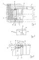
- Fig. 1 shows schematically a cold chamber die casting machine, in whose circular cylindrical casting cylinder 1, a piston 3 between an advanced position shown in FIG. 1 with solid lines and a 3 'dash-dotted retracted position is displaced.
- molten metal e.g. Aluminum melt
- the molten metal is pressed at high pressure via a sprue 9 in the injection mold, not shown.
- the piston 3 carries at its high-pressure end a fixed in two directions of movement sealing ring 11, the casting chamber 7 to Fill opening 5 seals off.
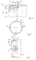
- the sealing ring 11 has, as shown in FIG. 2, a both axially and radially continuous step slot 13, which allows radial expansion of the sealing ring 11 due to inherent elasticity, so that the sealing ring 11 with an outer abutment annular surface 15 on the inner shell 17 of the casting cylinder. 1 biased due to its own radial elasticity, as best shown in FIG. 3.
- the extending in the circumferential direction in achsnormalen levels stages 19 at the step slot 13 forming ends of the annular body 21 of the sealing ring 11 abut each other and seal the step slot 13 axially.
- the piston 3 contains at 22 indicated, connected to a not-shown cooling system cooling channels, via which the piston 3 is cooled to a low temperature based on the temperature of the molten metal, for example 40 ° - 60 ° C. Details of the construction of a suitable in the context of the invention, cooled piston are also in EP 0 423 413 A2 as well as in EP 0 525 229 A1 described.
- the inner shell 17 of the casting cylinder 1 radially resilient annular body 21 of the sealing ring 11 includes near its low-pressure side axial end a circumferential groove 23 into which engages a radially projecting from the outer periphery of the piston 3, circumferential projection 25 and the sealing ring 11 in both displacement directions of the piston. 3 fixed on this.
- On the axially to the high pressure side of the piston 3 side of the annular groove 23 of the annular body 21 is dimensioned so that its inner shell 27 together with the outer shell of the piston 3 defines an annular gap 29 which is open to the high pressure side of the casting chamber.
- the investment annular surface 15 intended to bear against the inner jacket 17 of the casting cylinder 1 is smaller in the axial direction than the inner jacket surface 27 exposed to the melt pressure in the annular gap 29, so that a reinforcement of the radial compressive force acting on the abutment annular surface 15 results.
- This design of the sealing ring 11 and the piston 3 also allows lubrication of the piston during retraction in its position 3 '. It is known to fill not only the molten metal via the filling opening 5 of the casting cylinder 1 (FIG.
- the small axial height of the abutment annular surface 15 compared to the axial overall length of the annular body 21 facilitates initial grinding and fitting of the sealing ring 11 to the cylindrical surface 17.
- the frustoconical lateral surface 31 extends close to the high pressure end of the annular body 21, so that the Einschleif and fitting phase of the sealing ring 11 already after a few Casting cycles is completed.
- the abutment annular surface 15 becomes wider due to the wear.
- the outer shell of the annular body 21 on the low pressure side of the abutment annular surface 15 may also have a different contour, for example, a stepped, reduced in diameter cylinder contour, as indicated by dashed lines at 35 in Fig. 3.
- the contour 35 extends in the illustrated example to the low-pressure end of the annular body 21, but may also end in the ring body before this end and form a Schmierstofftechnischnut on the outer surface of the annular body 21.
- the annular recess 33 can be omitted here, as in the previously explained variants.
- FIGS. 4 and 5 show a variant of a in a casting cylinder 1 a displaceable piston 3a, which carries a sealing ring 11 a in the region of its high-pressure side end face.
- the sealing ring 11 a is provided according to the above-described sealing ring with a stepped slot and has an outer shell contour with a comparatively short in the axial direction abutment annular surface 15 a and a low pressure side subsequent frustoconical and low pressure side tapered outer sheath portion 31 a, as has been explained above , Also in this variant closes to the annular body 21 a of the sealing ring 1 1 a to the ring body 21 a and the inner shell 17 a through open ring recess 33 a.
- the sealing behavior, the Einschleif and the Lubricating behavior during retraction of the piston 3a thus corresponds to the embodiment of FIGS. 1 to 3.
- the piston 3a carries near its high-pressure end at its outer periphery an annular groove 37 into which the annular body 21 a engages over its entire axial length and in which it is fixed axially in both piston movement directions with a certain play.
- the high-pressure end of the piston 3a is arranged on its outer circumference with a plurality, here four, distributed in the circumferential direction , Trough-shaped recesses 39 which extend axially below the inner circumferential surface 27 a and in the bottom 41 of the ring body 21 a receiving annular recess 37 end. Via the recesses 39, molten metal flows into an annular gap 29 a formed between the bottom 41 of the annular recess 37 and the inner jacket 27 a of the annular body 21 a and increases the radial sealing pressure of the sealing ring 11 a.
- the annular gap 29a Since the annular gap 29a is connected to the casting chamber only via the circumferentially limited recesses 39, the annular gap 29a contains a melt distribution channel formed by a ring recess 43 of the piston 3a. It is understood that the recesses 39 may be provided wholly or additionally in the sealing ring 11a.
- FIG. 6 shows a variant of the piston of FIGS. 4 and 5, in which the high-pressure-side front end of the piston 3b is designed as a removable cover 47 which is fastened releasably to the piston 3b by means of a threaded projection 45.
- the separating surface 49 of the lid intersects the annular body 21 b of the sealing ring 11 b receiving annular recess 37 b of the piston 3 b and forms the high-pressure side limiting shoulder 51 of this annular recess 37 b.
- the radial height of the boundary shoulder 51 can now be chosen freely, since after removing the cover 47, the sealing ring 11 b can be pulled off axially.
- the design of the sealing ring 1 1 b corresponds to the explained with reference to FIGS. 4 and 5 variant, in which case the recesses 39 b are provided in the lid 47, but also here can extend to below the ring body 21 b.
- the lid 47 is made of a poorer heat-conducting material, such as steel or is thermally insulated by a ceramic coating to the cooling of the molten metal during the casting process in particular into the Nachtikphase in which cavities of the melt to be closed to delay.
Landscapes
- Engineering & Computer Science (AREA)
- Mechanical Engineering (AREA)
- Pistons, Piston Rings, And Cylinders (AREA)
- Encapsulation Of And Coatings For Semiconductor Or Solid State Devices (AREA)
- Forging (AREA)
- Injection Moulding Of Plastics Or The Like (AREA)
- Sealing Devices (AREA)
Claims (13)
- Bague d'étanchéité pour un piston d'un cylindre de coulée sous pression pour un bain de fusion métallique, en particulier un bain de fusion d'aluminium, avec un corps de bague radial élastique (21) qui comporte une fente (13) traversante aussi bien dans le sens axial que dans le sens radial, en particulier une fente à gradins dans la direction circonférentielle, caractérisée en ce que l'enveloppe extérieure du corps de bague (21) présente, à proximité de son extrémité axiale du côté haute pression, une surface d'appui de bague (15) définie pour l'appui sur la face de l'enveloppe intérieure (17) du cylindre de coulée sous pression (1), dont la longueur axiale est plus petite que la longueur axiale d'une surface de bague intérieure (27) sur l'enveloppe intérieure du corps de bague (21) se chevauchant axialement avec cette surface d'appui de bague extérieure (15) à exposer au bain de fusion métallique et en ce que, du côté basse pression de la surface d'appui de bague extérieure (15), un segment de surface de bague (31 ; 35) est raccordé à la surface d'appui de bague extérieure (15) au moins sur une portion partielle de la longueur axiale restante de l'enveloppe extérieure du corps de bague (21), segment dont le diamètre est plus petit que le diamètre de la surface d'appui de bague extérieure (15).
- Bague d'étanchéité selon la revendication 1, caractérisée en ce que le segment de surface de bague extérieur (31 ; 35) ayant un diamètre réduit s'étend jusqu'à l'extrémité axiale du côté basse pression du corps de bague (21).
- Bague d'étanchéité selon la revendication 2, caractérisée en ce que le segment de surface de bague (31) ayant un diamètre réduit a une forme au moins à peu près tronconique et s'amincit en direction de l'extrémité axiale du côté basse pression du corps de bague (21).
- Bague d'étanchéité selon l'une quelconque des revendications 1 à 3, caractérisée en ce que l'enveloppe intérieure du corps de bague (21), en particulier à proximité de son extrémité axiale du côté basse pression, présente un évidement annulaire circulaire (23).
- Piston pour un cylindre de coulée sous pression pour un bain de fusion métallique, en particulier un bain de fusion d'aluminium, avec une bague d'étanchéité (11) fixée axialement à proximité de l'extrémité du piston du côté haute pression selon l'une quelconque des revendications 1 à 4, caractérisé en ce que la surface de bague intérieure (27) de l'enveloppe intérieure du corps de bague (21) à exposer au bain de fusion métallique forme, conjointement avec l'enveloppe extérieure du piston (3), une fente annulaire (29) ouverte vers la chambre de pression (7) du cylindre de coulée sous pression (1) du côté haute pression du corps de bague (21).
- Piston selon la revendication 5, caractérisé en ce qu'il comporte un épaulement annulaire (25) faisant saillie radialement qui, pour la fixation axiale du corps de bague (21) sur le piston (3), vient en prise dans une rainure annulaire (23) disposée dans l'enveloppe intérieure (27) du corps de bague (21) du côté basse pression de la fente annulaire (29).
- Piston selon la revendication 5, caractérisé en ce qu'il comporte sur son enveloppe extérieure un évidement annulaire (37) dans lequel le corps de bague (21 a) vient en prise pour sa fixation axiale en formant la fente annulaire (29a), et en ce que le piston (3a) comporte plusieurs évidements (39) répartis dans la direction circonférentielle, partant de l'extrémité frontale du côté haute pression du piston (3a), débouchant dans la fente annulaire (29a).
- Piston selon la revendication 7, caractérisé en ce qu'une rainure de distribution de bain circulaire (43) est disposée dans l'une des deux enveloppes formant la fente annulaire (39), en particulier l'enveloppe extérieure de l'évidement annulaire (37).
- Piston selon la revendication 7 ou 8, caractérisé en ce que sa face frontale du côté haute pression est conçue comme un couvercle amovible (47), en particulier dévissable, dont la surface de séparation (49) se termine dans l'évidement annulaire (37b) qui maintient le corps de bague (21b).
- Piston selon la revendication 9, caractérisé en ce que le couvercle (47) est constitué d'une matière ayant une plus mauvaise conductibilité thermique que la portion du piston (3b) raccordée à celui-ci.
- Piston selon la revendication 9 ou 10, caractérisé en ce que le couvercle (47) est constitué d'acier ou d'un alliage de cuivre et/ou en ce qu'il est revêtu d'une matière céramique.
- Piston selon l'une quelconque des revendications 5 à 11, caractérisé en ce qu'il comporte dans son enveloppe extérieure un évidement annulaire (33) ouvert vers l'enveloppe intérieure du cylindre (17) et vers le corps de bague (21) directement raccordé à l'extrémité du côté basse pression du corps de bague (21) de la bague d'étanchéité (11) pour former un espace de lubrifiant.
- Piston selon l'une quelconque des revendications 5 à 12, caractérisé en ce qu'il comporte des moyens de refroidissement du piston dans la zone de la bague d'étanchéité (11).
Applications Claiming Priority (1)
| Application Number | Priority Date | Filing Date | Title |
|---|---|---|---|
| PCT/EP2002/002356 WO2003074214A1 (fr) | 2002-03-04 | 2002-03-04 | Bague d'etancheite et piston pour un cylindre de coulee sous pression |
Publications (2)
| Publication Number | Publication Date |
|---|---|
| EP1483074A1 EP1483074A1 (fr) | 2004-12-08 |
| EP1483074B1 true EP1483074B1 (fr) | 2007-06-13 |
Family
ID=27771816
Family Applications (2)
| Application Number | Title | Priority Date | Filing Date |
|---|---|---|---|
| EP02727355A Expired - Lifetime EP1483074B1 (fr) | 2002-03-04 | 2002-03-04 | Bague d'etancheite et piston pour un cylindre de coulee sous pression |
| EP02792752A Withdrawn EP1483075A2 (fr) | 2002-03-04 | 2002-11-11 | Piston con u pour une machine a coulee sous pression a chambre froide |
Family Applications After (1)
| Application Number | Title | Priority Date | Filing Date |
|---|---|---|---|
| EP02792752A Withdrawn EP1483075A2 (fr) | 2002-03-04 | 2002-11-11 | Piston con u pour une machine a coulee sous pression a chambre froide |
Country Status (6)
| Country | Link |
|---|---|
| EP (2) | EP1483074B1 (fr) |
| AT (1) | ATE364464T1 (fr) |
| AU (2) | AU2002257612A1 (fr) |
| DE (1) | DE50210331D1 (fr) |
| ES (1) | ES2287274T3 (fr) |
| WO (2) | WO2003074214A1 (fr) |
Cited By (4)
| Publication number | Priority date | Publication date | Assignee | Title |
|---|---|---|---|---|
| DE102009057197B3 (de) * | 2009-11-30 | 2011-05-19 | Oskar Frech Gmbh + Co. Kg | Gießeinheit für eine Druckgießmaschine |
| EP2554296A2 (fr) | 2011-08-05 | 2013-02-06 | Schmelzmetall AG | Piston de coulée sous pression |
| KR20190040139A (ko) * | 2016-08-29 | 2019-04-17 | 코프로멕 다이 캐스팅 에스.알.엘. 어 소시오 유니코 | 다이 캐스팅 장치의 피스톤 |
| DE102024122724B3 (de) * | 2024-08-08 | 2025-11-20 | Oskar Frech Gmbh + Co. Kg | Gießkolben für eine Gießmaschine |
Families Citing this family (8)
| Publication number | Priority date | Publication date | Assignee | Title |
|---|---|---|---|---|
| DE20309181U1 (de) * | 2003-06-13 | 2004-10-28 | Allper Ag | Mehrteiliger Kolben für eine Kaltkammer-Druckgießmaschine |
| DE102005048717A1 (de) | 2005-10-12 | 2007-04-19 | Allper Ag | Mehrteiliger Kolben für eine Kaltkammer-Giessmaschine |
| ITBS20060087A1 (it) * | 2006-04-12 | 2007-10-13 | Copromec S R L | Pistone per macchine per la pressofusione a camera fredda |
| BRPI0703362A2 (pt) * | 2007-08-15 | 2009-03-31 | W Fischer Tecnica Ltda | pistão para injeção de metal fundido |
| IT1393330B1 (it) * | 2009-01-21 | 2012-04-20 | Brondolin S P A | Pistoni per pressofusione |
| IT1393329B1 (it) * | 2009-01-21 | 2012-04-20 | Brondolin S P A | Pistone e anello di tenuta per pressofusione |
| TW201501838A (zh) | 2013-04-04 | 2015-01-16 | Gani Murselaj | 用於金屬模鑄之活塞 |
| DE102014018795A1 (de) * | 2014-12-19 | 2016-06-23 | Gebr. Krallmann Gmbh | Fördervorrichtung für eine Metallschmelze in einem Spritzgussaggregat |
Family Cites Families (6)
| Publication number | Priority date | Publication date | Assignee | Title |
|---|---|---|---|---|
| DE1080739B (de) * | 1957-11-16 | 1960-04-28 | Friedr Fingscheidt G M B H | Kolben fuer Druckgiessmaschinen |
| US4899804A (en) * | 1989-02-21 | 1990-02-13 | Hammerer Norman L | Plunger tip for cold chamber die cast machine |
| US5048592A (en) * | 1989-10-18 | 1991-09-17 | Allper Ag | Plunger for a diecasting machine |
| ES2095886T3 (es) * | 1991-07-29 | 1997-03-01 | Allper Ag | Embolo, particularmente para empujar metal liquido fuera de un cilindro de colada. |
| JP2517509B2 (ja) * | 1992-01-30 | 1996-07-24 | 日本軽金属株式会社 | ホットチャンバ―ダイカストマシンの射出用プランジャ― |
| IT250574Y1 (it) * | 2000-10-13 | 2003-09-24 | Copromec S R L | Pistone per la pressofusione a camera fredda |
-
2002
- 2002-03-04 WO PCT/EP2002/002356 patent/WO2003074214A1/fr not_active Ceased
- 2002-03-04 ES ES02727355T patent/ES2287274T3/es not_active Expired - Lifetime
- 2002-03-04 EP EP02727355A patent/EP1483074B1/fr not_active Expired - Lifetime
- 2002-03-04 DE DE50210331T patent/DE50210331D1/de not_active Expired - Fee Related
- 2002-03-04 AU AU2002257612A patent/AU2002257612A1/en not_active Abandoned
- 2002-03-04 AT AT02727355T patent/ATE364464T1/de not_active IP Right Cessation
- 2002-11-11 EP EP02792752A patent/EP1483075A2/fr not_active Withdrawn
- 2002-11-11 AU AU2002358495A patent/AU2002358495A1/en not_active Abandoned
- 2002-11-11 WO PCT/EP2002/012585 patent/WO2003074211A2/fr not_active Ceased
Cited By (9)
| Publication number | Priority date | Publication date | Assignee | Title |
|---|---|---|---|---|
| DE102009057197B3 (de) * | 2009-11-30 | 2011-05-19 | Oskar Frech Gmbh + Co. Kg | Gießeinheit für eine Druckgießmaschine |
| WO2011064253A1 (fr) | 2009-11-30 | 2011-06-03 | Oskar Frech Gmbh + Co. Kg | Unité de coulée destinée à une machine à coulée sous pression |
| US9233417B2 (en) | 2009-11-30 | 2016-01-12 | Oskar Frech Gmbh + Co. Kg | Casting unit for a diecasting machine |
| EP2554296A2 (fr) | 2011-08-05 | 2013-02-06 | Schmelzmetall AG | Piston de coulée sous pression |
| DE102011052446A1 (de) | 2011-08-05 | 2013-02-07 | Schmelzmetall Ag | Druckgusskolbenkopf |
| KR20190040139A (ko) * | 2016-08-29 | 2019-04-17 | 코프로멕 다이 캐스팅 에스.알.엘. 어 소시오 유니코 | 다이 캐스팅 장치의 피스톤 |
| KR102402585B1 (ko) | 2016-08-29 | 2022-05-26 | 코프로멕 다이 캐스팅 에스.알.엘. 어 소시오 유니코 | 다이 캐스팅 장치의 피스톤 |
| DE102024122724B3 (de) * | 2024-08-08 | 2025-11-20 | Oskar Frech Gmbh + Co. Kg | Gießkolben für eine Gießmaschine |
| WO2026032625A1 (fr) | 2024-08-08 | 2026-02-12 | Oskar Frech Gmbh + Co. Kg | Piston de coulée pour une machine de coulée |
Also Published As
| Publication number | Publication date |
|---|---|
| DE50210331D1 (de) | 2007-07-26 |
| WO2003074214A1 (fr) | 2003-09-12 |
| AU2002257612A1 (en) | 2003-09-16 |
| EP1483074A1 (fr) | 2004-12-08 |
| ATE364464T1 (de) | 2007-07-15 |
| EP1483075A2 (fr) | 2004-12-08 |
| AU2002358495A1 (en) | 2003-09-16 |
| WO2003074211A3 (fr) | 2004-06-10 |
| ES2287274T3 (es) | 2007-12-16 |
| AU2002358495A8 (en) | 2003-09-16 |
| WO2003074211A2 (fr) | 2003-09-12 |
Similar Documents
| Publication | Publication Date | Title |
|---|---|---|
| EP0423413B1 (fr) | Piston, notamment pour un appareil de coulée sous pression | |
| EP1483074B1 (fr) | Bague d'etancheite et piston pour un cylindre de coulee sous pression | |
| DE4112889C2 (de) | Verfahren zur Herstellung eines Kolbenkopfes mit Kühlung für einen mehrteiligen, gegliederten Kolben für Verbrennungsmotore, sowie danach hergestellter Kolbenkopf | |
| DE102005029417A1 (de) | Verfahren zur Herstellung eines Kolbens für einen Verbrennungsmotor | |
| DE3412175A1 (de) | Tassenfoermiges gehaeuse eines sich selbsttaetig hydraulisch einstellenden ventilstoessels fuer brennkraftmaschinen mit obenliegender nockenwelle | |
| EP3334918B1 (fr) | Piston pour moteur à combustion interne | |
| DE10058428A1 (de) | Zylinderlaufbuchse und Zylinderblock sowie Verfahren zur Herstellung derselben | |
| DE2953435C2 (de) | Druckgießmaschine zur Durchführung eines Druckgießverfahrens mit Nachverdichtung | |
| EP1963654B1 (fr) | Piston pour moteur a combustion interne | |
| EP0255475B1 (fr) | Cylindre de remplissage pour machines de coulée sous pression | |
| EP2506999B1 (fr) | Ensemble d'injection pour machine a couler sous pression | |
| EP2823166A1 (fr) | Piston coulé en alliage léger, notamment piston en aluminium | |
| EP1635973B1 (fr) | Piston destine a une machine pour coulee sous pression en chambre froide | |
| DE19621894B4 (de) | Brennkraftmaschine mit Kolbenkühlung | |
| EP0893182B1 (fr) | Procédé pour la fabrication d'une chemise de cylindre d'un moteur à combustion interne | |
| DE19847865C2 (de) | Zylinderlaufbuchse | |
| DE4308751A1 (de) | Kolben-Pleuel-Anordnung für Brennkraftmaschinen | |
| DE19938075A1 (de) | Preßkolben und Verfahren zum Schmieren eines Preßkolbens | |
| DE873185C (de) | Kolben, insbesondere fuer Brennkraftmaschinen | |
| DE19954725A1 (de) | Kolben mit einer Verbindung von einem Kühlkanal zu einer Kolbenbolzenbohrung | |
| EP3502453B1 (fr) | Piston pour un moteur à combustion interne alternatif | |
| EP1439927B1 (fr) | Carter de vilebrequin de cylindre comportant une chemise de cylindre et outil de coulage | |
| EP0901852A1 (fr) | Piston pour une machine à couler sous pression à chambre chaude | |
| EP1704319B1 (fr) | Carter de vilebrequin cylindrique comportant une chemise de piston | |
| DE29521266U1 (de) | Vorrichtung zum Befüllen eines Gießwerkzeugs mit einer Metallschmelze |
Legal Events
| Date | Code | Title | Description |
|---|---|---|---|
| PUAI | Public reference made under article 153(3) epc to a published international application that has entered the european phase |
Free format text: ORIGINAL CODE: 0009012 |
|
| 17P | Request for examination filed |
Effective date: 20041001 |
|
| AK | Designated contracting states |
Kind code of ref document: A1 Designated state(s): AT BE CH CY DE DK ES FI FR GB GR IE IT LI LU MC NL PT SE TR |
|
| AX | Request for extension of the european patent |
Extension state: AL LT LV MK RO SI |
|
| GRAP | Despatch of communication of intention to grant a patent |
Free format text: ORIGINAL CODE: EPIDOSNIGR1 |
|
| GRAS | Grant fee paid |
Free format text: ORIGINAL CODE: EPIDOSNIGR3 |
|
| GRAA | (expected) grant |
Free format text: ORIGINAL CODE: 0009210 |
|
| AK | Designated contracting states |
Kind code of ref document: B1 Designated state(s): AT BE CH CY DE DK ES FI FR GB GR IE IT LI LU MC NL PT SE TR |
|
| REG | Reference to a national code |
Ref country code: GB Ref legal event code: FG4D Free format text: NOT ENGLISH |
|
| REG | Reference to a national code |
Ref country code: CH Ref legal event code: EP |
|
| GBT | Gb: translation of ep patent filed (gb section 77(6)(a)/1977) |
Effective date: 20070613 |
|
| REG | Reference to a national code |
Ref country code: IE Ref legal event code: FG4D Free format text: LANGUAGE OF EP DOCUMENT: GERMAN |
|
| REF | Corresponds to: |
Ref document number: 50210331 Country of ref document: DE Date of ref document: 20070726 Kind code of ref document: P |
|
| PG25 | Lapsed in a contracting state [announced via postgrant information from national office to epo] |
Ref country code: SE Free format text: LAPSE BECAUSE OF FAILURE TO SUBMIT A TRANSLATION OF THE DESCRIPTION OR TO PAY THE FEE WITHIN THE PRESCRIBED TIME-LIMIT Effective date: 20070913 |
|
| ET | Fr: translation filed | ||
| REG | Reference to a national code |
Ref country code: CH Ref legal event code: NV Representative=s name: A. BRAUN, BRAUN, HERITIER, ESCHMANN AG PATENTANWAE |
|
| NLV1 | Nl: lapsed or annulled due to failure to fulfill the requirements of art. 29p and 29m of the patents act | ||
| REG | Reference to a national code |
Ref country code: ES Ref legal event code: FG2A Ref document number: 2287274 Country of ref document: ES Kind code of ref document: T3 |
|
| REG | Reference to a national code |
Ref country code: IE Ref legal event code: FD4D |
|
| PG25 | Lapsed in a contracting state [announced via postgrant information from national office to epo] |
Ref country code: IE Free format text: LAPSE BECAUSE OF FAILURE TO SUBMIT A TRANSLATION OF THE DESCRIPTION OR TO PAY THE FEE WITHIN THE PRESCRIBED TIME-LIMIT Effective date: 20070613 Ref country code: NL Free format text: LAPSE BECAUSE OF FAILURE TO SUBMIT A TRANSLATION OF THE DESCRIPTION OR TO PAY THE FEE WITHIN THE PRESCRIBED TIME-LIMIT Effective date: 20070613 Ref country code: PT Free format text: LAPSE BECAUSE OF FAILURE TO SUBMIT A TRANSLATION OF THE DESCRIPTION OR TO PAY THE FEE WITHIN THE PRESCRIBED TIME-LIMIT Effective date: 20071113 |
|
| PLBE | No opposition filed within time limit |
Free format text: ORIGINAL CODE: 0009261 |
|
| STAA | Information on the status of an ep patent application or granted ep patent |
Free format text: STATUS: NO OPPOSITION FILED WITHIN TIME LIMIT |
|
| PG25 | Lapsed in a contracting state [announced via postgrant information from national office to epo] |
Ref country code: DK Free format text: LAPSE BECAUSE OF FAILURE TO SUBMIT A TRANSLATION OF THE DESCRIPTION OR TO PAY THE FEE WITHIN THE PRESCRIBED TIME-LIMIT Effective date: 20070613 Ref country code: GR Free format text: LAPSE BECAUSE OF FAILURE TO SUBMIT A TRANSLATION OF THE DESCRIPTION OR TO PAY THE FEE WITHIN THE PRESCRIBED TIME-LIMIT Effective date: 20070914 |
|
| PGFP | Annual fee paid to national office [announced via postgrant information from national office to epo] |
Ref country code: ES Payment date: 20080328 Year of fee payment: 7 |
|
| 26N | No opposition filed |
Effective date: 20080314 |
|
| PGFP | Annual fee paid to national office [announced via postgrant information from national office to epo] |
Ref country code: IT Payment date: 20080326 Year of fee payment: 7 |
|
| REG | Reference to a national code |
Ref country code: CH Ref legal event code: PFA Owner name: ALLPER AG Free format text: ALLPER AG#WARPELSTRASSE 10#3186 DUEDINGEN (CH) -TRANSFER TO- ALLPER AG#WARPELSTRASSE 10#3186 DUEDINGEN (CH) |
|
| PGFP | Annual fee paid to national office [announced via postgrant information from national office to epo] |
Ref country code: AT Payment date: 20080314 Year of fee payment: 7 |
|
| PGFP | Annual fee paid to national office [announced via postgrant information from national office to epo] |
Ref country code: DE Payment date: 20080229 Year of fee payment: 7 |
|
| BERE | Be: lapsed |
Owner name: ALLPER A.G. Effective date: 20080331 |
|
| PG25 | Lapsed in a contracting state [announced via postgrant information from national office to epo] |
Ref country code: MC Free format text: LAPSE BECAUSE OF NON-PAYMENT OF DUE FEES Effective date: 20080331 |
|
| REG | Reference to a national code |
Ref country code: CH Ref legal event code: PL |
|
| GBPC | Gb: european patent ceased through non-payment of renewal fee |
Effective date: 20080304 |
|
| REG | Reference to a national code |
Ref country code: FR Ref legal event code: ST Effective date: 20081125 |
|
| PG25 | Lapsed in a contracting state [announced via postgrant information from national office to epo] |
Ref country code: CH Free format text: LAPSE BECAUSE OF NON-PAYMENT OF DUE FEES Effective date: 20080331 Ref country code: LI Free format text: LAPSE BECAUSE OF NON-PAYMENT OF DUE FEES Effective date: 20080331 |
|
| PG25 | Lapsed in a contracting state [announced via postgrant information from national office to epo] |
Ref country code: BE Free format text: LAPSE BECAUSE OF NON-PAYMENT OF DUE FEES Effective date: 20080331 Ref country code: FI Free format text: LAPSE BECAUSE OF FAILURE TO SUBMIT A TRANSLATION OF THE DESCRIPTION OR TO PAY THE FEE WITHIN THE PRESCRIBED TIME-LIMIT Effective date: 20070613 |
|
| PG25 | Lapsed in a contracting state [announced via postgrant information from national office to epo] |
Ref country code: FR Free format text: LAPSE BECAUSE OF NON-PAYMENT OF DUE FEES Effective date: 20080331 |
|
| PG25 | Lapsed in a contracting state [announced via postgrant information from national office to epo] |
Ref country code: GB Free format text: LAPSE BECAUSE OF NON-PAYMENT OF DUE FEES Effective date: 20080304 |
|
| PG25 | Lapsed in a contracting state [announced via postgrant information from national office to epo] |
Ref country code: CY Free format text: LAPSE BECAUSE OF FAILURE TO SUBMIT A TRANSLATION OF THE DESCRIPTION OR TO PAY THE FEE WITHIN THE PRESCRIBED TIME-LIMIT Effective date: 20070613 |
|
| PG25 | Lapsed in a contracting state [announced via postgrant information from national office to epo] |
Ref country code: AT Free format text: LAPSE BECAUSE OF NON-PAYMENT OF DUE FEES Effective date: 20090304 |
|
| PG25 | Lapsed in a contracting state [announced via postgrant information from national office to epo] |
Ref country code: DE Free format text: LAPSE BECAUSE OF NON-PAYMENT OF DUE FEES Effective date: 20091001 |
|
| REG | Reference to a national code |
Ref country code: ES Ref legal event code: FD2A Effective date: 20090305 |
|
| PG25 | Lapsed in a contracting state [announced via postgrant information from national office to epo] |
Ref country code: LU Free format text: LAPSE BECAUSE OF NON-PAYMENT OF DUE FEES Effective date: 20080304 Ref country code: ES Free format text: LAPSE BECAUSE OF NON-PAYMENT OF DUE FEES Effective date: 20090305 |
|
| PG25 | Lapsed in a contracting state [announced via postgrant information from national office to epo] |
Ref country code: TR Free format text: LAPSE BECAUSE OF FAILURE TO SUBMIT A TRANSLATION OF THE DESCRIPTION OR TO PAY THE FEE WITHIN THE PRESCRIBED TIME-LIMIT Effective date: 20070613 |
|
| PG25 | Lapsed in a contracting state [announced via postgrant information from national office to epo] |
Ref country code: IT Free format text: LAPSE BECAUSE OF NON-PAYMENT OF DUE FEES Effective date: 20090304 |