EP1483092B1 - Procede et dispositif de reglage de precontrainte des lames d'un dispositif de granulation - Google Patents
Procede et dispositif de reglage de precontrainte des lames d'un dispositif de granulation Download PDFInfo
- Publication number
- EP1483092B1 EP1483092B1 EP02748412A EP02748412A EP1483092B1 EP 1483092 B1 EP1483092 B1 EP 1483092B1 EP 02748412 A EP02748412 A EP 02748412A EP 02748412 A EP02748412 A EP 02748412A EP 1483092 B1 EP1483092 B1 EP 1483092B1
- Authority
- EP
- European Patent Office
- Prior art keywords
- shaft
- sub
- motor
- granulating
- torque
- Prior art date
- Legal status (The legal status is an assumption and is not a legal conclusion. Google has not performed a legal analysis and makes no representation as to the accuracy of the status listed.)
- Expired - Lifetime
Links
- 238000000034 method Methods 0.000 claims abstract description 37
- 230000008569 process Effects 0.000 claims description 21
- 238000005259 measurement Methods 0.000 claims description 8
- 239000000463 material Substances 0.000 claims description 7
- 230000001105 regulatory effect Effects 0.000 claims 1
- 239000012815 thermoplastic material Substances 0.000 claims 1
- 238000006073 displacement reaction Methods 0.000 abstract description 11
- 238000005469 granulation Methods 0.000 description 12
- 230000003179 granulation Effects 0.000 description 12
- 238000005520 cutting process Methods 0.000 description 7
- 239000004033 plastic Substances 0.000 description 7
- 239000002826 coolant Substances 0.000 description 6
- 239000000155 melt Substances 0.000 description 6
- 238000006243 chemical reaction Methods 0.000 description 5
- 230000001419 dependent effect Effects 0.000 description 5
- 238000010276 construction Methods 0.000 description 4
- 238000002474 experimental method Methods 0.000 description 3
- 239000008187 granular material Substances 0.000 description 3
- XLYOFNOQVPJJNP-UHFFFAOYSA-N water Substances O XLYOFNOQVPJJNP-UHFFFAOYSA-N 0.000 description 3
- 230000006978 adaptation Effects 0.000 description 2
- 238000005452 bending Methods 0.000 description 2
- 230000008859 change Effects 0.000 description 2
- 238000013461 design Methods 0.000 description 2
- 238000005265 energy consumption Methods 0.000 description 2
- 230000002349 favourable effect Effects 0.000 description 2
- 238000009499 grossing Methods 0.000 description 2
- 238000003825 pressing Methods 0.000 description 2
- 230000008719 thickening Effects 0.000 description 2
- 230000001133 acceleration Effects 0.000 description 1
- 230000009471 action Effects 0.000 description 1
- 230000004888 barrier function Effects 0.000 description 1
- 230000005540 biological transmission Effects 0.000 description 1
- 230000015572 biosynthetic process Effects 0.000 description 1
- 230000008878 coupling Effects 0.000 description 1
- 238000010168 coupling process Methods 0.000 description 1
- 238000005859 coupling reaction Methods 0.000 description 1
- 238000011161 development Methods 0.000 description 1
- 238000010586 diagram Methods 0.000 description 1
- 238000011156 evaluation Methods 0.000 description 1
- 235000013305 food Nutrition 0.000 description 1
- 239000012535 impurity Substances 0.000 description 1
- 238000004519 manufacturing process Methods 0.000 description 1
- 230000007935 neutral effect Effects 0.000 description 1
- 239000002245 particle Substances 0.000 description 1
- 235000015927 pasta Nutrition 0.000 description 1
- 235000011837 pasties Nutrition 0.000 description 1
- 238000005453 pelletization Methods 0.000 description 1
- 230000036316 preload Effects 0.000 description 1
- 238000012545 processing Methods 0.000 description 1
- 238000005096 rolling process Methods 0.000 description 1
- 230000011664 signaling Effects 0.000 description 1
- 125000006850 spacer group Chemical group 0.000 description 1
- 229920001169 thermoplastic Polymers 0.000 description 1
- 239000004416 thermosoftening plastic Substances 0.000 description 1
Images


Classifications
-
- B—PERFORMING OPERATIONS; TRANSPORTING
- B29—WORKING OF PLASTICS; WORKING OF SUBSTANCES IN A PLASTIC STATE IN GENERAL
- B29B—PREPARATION OR PRETREATMENT OF THE MATERIAL TO BE SHAPED; MAKING GRANULES OR PREFORMS; RECOVERY OF PLASTICS OR OTHER CONSTITUENTS OF WASTE MATERIAL CONTAINING PLASTICS
- B29B9/00—Making granules
- B29B9/02—Making granules by dividing preformed material
- B29B9/06—Making granules by dividing preformed material in the form of filamentary material, e.g. combined with extrusion
- B29B9/065—Making granules by dividing preformed material in the form of filamentary material, e.g. combined with extrusion under-water, e.g. underwater pelletizers
-
- B—PERFORMING OPERATIONS; TRANSPORTING
- B26—HAND CUTTING TOOLS; CUTTING; SEVERING
- B26D—CUTTING; DETAILS COMMON TO MACHINES FOR PERFORATING, PUNCHING, CUTTING-OUT, STAMPING-OUT OR SEVERING
- B26D7/00—Details of apparatus for cutting, cutting-out, stamping-out, punching, perforating, or severing by means other than cutting
- B26D7/26—Means for mounting or adjusting the cutting member; Means for adjusting the stroke of the cutting member
-
- B—PERFORMING OPERATIONS; TRANSPORTING
- B29—WORKING OF PLASTICS; WORKING OF SUBSTANCES IN A PLASTIC STATE IN GENERAL
- B29C—SHAPING OR JOINING OF PLASTICS; SHAPING OF MATERIAL IN A PLASTIC STATE, NOT OTHERWISE PROVIDED FOR; AFTER-TREATMENT OF THE SHAPED PRODUCTS, e.g. REPAIRING
- B29C48/00—Extrusion moulding, i.e. expressing the moulding material through a die or nozzle which imparts the desired form; Apparatus therefor
- B29C48/03—Extrusion moulding, i.e. expressing the moulding material through a die or nozzle which imparts the desired form; Apparatus therefor characterised by the shape of the extruded material at extrusion
- B29C48/04—Particle-shaped
-
- B—PERFORMING OPERATIONS; TRANSPORTING
- B29—WORKING OF PLASTICS; WORKING OF SUBSTANCES IN A PLASTIC STATE IN GENERAL
- B29C—SHAPING OR JOINING OF PLASTICS; SHAPING OF MATERIAL IN A PLASTIC STATE, NOT OTHERWISE PROVIDED FOR; AFTER-TREATMENT OF THE SHAPED PRODUCTS, e.g. REPAIRING
- B29C48/00—Extrusion moulding, i.e. expressing the moulding material through a die or nozzle which imparts the desired form; Apparatus therefor
- B29C48/03—Extrusion moulding, i.e. expressing the moulding material through a die or nozzle which imparts the desired form; Apparatus therefor characterised by the shape of the extruded material at extrusion
- B29C48/05—Filamentary, e.g. strands
-
- B—PERFORMING OPERATIONS; TRANSPORTING
- B29—WORKING OF PLASTICS; WORKING OF SUBSTANCES IN A PLASTIC STATE IN GENERAL
- B29C—SHAPING OR JOINING OF PLASTICS; SHAPING OF MATERIAL IN A PLASTIC STATE, NOT OTHERWISE PROVIDED FOR; AFTER-TREATMENT OF THE SHAPED PRODUCTS, e.g. REPAIRING
- B29C48/00—Extrusion moulding, i.e. expressing the moulding material through a die or nozzle which imparts the desired form; Apparatus therefor
- B29C48/25—Component parts, details or accessories; Auxiliary operations
- B29C48/30—Extrusion nozzles or dies
- B29C48/32—Extrusion nozzles or dies with annular openings, e.g. for forming tubular articles
- B29C48/34—Cross-head annular extrusion nozzles, i.e. for simultaneously receiving moulding material and the preform to be coated
Definitions
- the invention relates to a method for adjusting a bias, with which blades of one of a driven by a motor, slidable shaft in the axial direction Granulierkopfes a granulating abut the perforated plate, fed through the holes of the material to be granulated, in particular thermoplastic is, wherein the torque of the motor is used for this setting. Furthermore, the invention relates to an apparatus for carrying out such a method.
- EP 418 941 A2 for an underwater granulating device, wherein the power consumption of the drive motor of the granulating shaft is utilized to determine the size of the hydrodynamic force occurring during the knife circulation.
- the object of the invention is to improve a method of the type described above in such a way that a reliable and as even as possible pressing of the blades on the perforated plate of the granulating device is achieved, aiming for the most favorable values in terms of knife wear, perforated plate wear and energy consumption of the motor are.
- the invention proceeds hiebei from the knowledge gained by experiments that at constant throughput of the granulator and constant speed of the granulation of the torque of the drive motor of the granulation at a certain feed position thereof has a minimum, and increases in displacement in both directions from this minimum position.
- this minimum position x 0 is the position at which the granulating blades just touch the perforated plate, but bear against it without pressure. In practice, however, this position, in which the wear of the granulator and the perforated plate is theoretically lowest, not met, since due to manufacturing tolerances and by the pressure of emerging from the perforated plate melt strand low contact forces of the pelletizer are necessary.
- This specific bias of the pelletizer is dependent on the processed material, which is usually plastic, but may also be formed by another pasty mass, such as a food mass, such as pasta, muesli, etc. Furthermore, this specific bias voltage depends on the processing conditions. It must therefore be adapted to the particular case at hand. If this happens in the sense of the invention, then there is a reliable Andschreibung the knife to the perforated plate and thus a good granule quality, but also a low energy consumption and low wear of the knife and the perforated plate, because by a suitable free choice of the process-dependent bias can be the life extend the granulator blade. It is also possible to control the bias voltage via current process data and to change it during operation. Examples of such variable process data are throughput and the type of processed material, in particular plastic. Likewise, by this method, the wear of the pelletizer can be compensated by ongoing adjustment.
- the adjustment of the shaft in two axial directions between two positions x 1 , x 2 is performed, which two predetermined limits ⁇ , ⁇ for d M d x for which applies ⁇ ⁇ 0 and ⁇ > 0.
- the procedure according to the invention proceeds in such a way that, prior to the formation of the differential d M d x the torque curve of the engine is filtered by a low-pass filter.
- This low-pass filter smoothes the output of the device, which senses the torque of the motor and converts it into an electrical output signal.
- the procedure is repeated such that the measurements are repeated at intervals and the adjustment of the bias voltage is changed accordingly.
- the device according to the invention for carrying out the method according to the invention is based on a construction with a perforated plate, for example an extruder, at the holes of which at least one knife carried by a granulating head of a granulator is pressed with prestress, which granulating head is carried within a granulating housing by a shaft which slidable in the axial direction in the Granuliergeophuse and is driven by a motor for rotational movement about its axis, wherein a sensing device for the time course of the torque of the motor is provided, whose output signal influences an actuator for the displacement of the shaft.
- the actuator is controlled in the context of the method according to the invention.
- a device smoothing the output signal of this device is connected to the sensing device for the time characteristic of the torque of the motor, in order to avoid distortions of the measurement result by peaks occurring in the output signal of this sensing device.
- an input unit is provided for the repetition of the measurements at predetermined time intervals.
- This input unit can be operated manually or automatically, expediently in freely selectable time intervals.
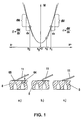
- FIG. 1 shows the idealized, calculated course of the torque of the drive motor of the granulating shaft as a function of the displacement position of the granulating shaft.
- 2 shows the torque curve determined by measurement and its differentiated graph via the displacement path.
- Fig. 3 is a block diagram of the control unit for axial displacement of the granulating blade shaft, and
- Fig. 4 is a longitudinal sectional view of a granulating device.
- the power requirement of the motor 21 (FIGS. 3, 4) of the granulating device is determined and evaluated.
- P f M for constant n > 0
- M M Neutral + M friction + M gap + M plastic + M cut
- M section is the reaction torque due to the section through the melt strand
- M idling the reaction torque due to the mechanical structure (including bearing friction and aerodynamic forces)
- M friction the reaction torque due to the friction of the granulating to the perforated plate
- M nip the reaction torque due to increased apparent friction due to cutting gap and thickening of the melt film
- M plastic the reaction torque due to the exiting plastic melt (including acceleration forces and cutting forces, ie essentially specific plastic characteristics and output-specific sizes).
- This operating state corresponds to the graph a) in FIG. 1.
- .DELTA.M M gap . x ⁇ 2 - M gap . x ⁇ 1 + M friction . x ⁇ 2 - M friction . x ⁇ 1
- the torque applied by the drive motor 21 for rotating the blade shaft 12 ( Figure 4) is continuously measured. This is done by means of a sensing device 66 (FIG. 3) of any type.
- the timing of the discrete triggering times t can be done manually in any way, or automatically by a measuring time 67, at least immediately after the start of the granulation.
- the output signal of the sensing device 66 reaches a low-pass filter 68, which causes a smoothing of the output from the sensing device 66 signal. From the shown in Fig. 2, a little troubled measurement result for M, which is obtained when advancing the blade shaft 12, then results in a smoothed curve, as shown in FIG 1.
- the output signal of the filter 68 reaches a differentiator 69, through which the signal for M (x) the signal d M d x (x) is formed (Fig. 2).
- x z is thus a parameter dependent on the process conditions, which can also be changed during operation, in particular for adaptation to changing process conditions.
- the parameter x z can be input by an input unit 73 connected to the logic circuit 70 or read from a process database. This input unit 73 can also be used to determine the intervals of the setting process, so that in such a configuration of the circuit of the measuring timing generator 67 can be omitted for Einstellintervalle.
- the parameter x z is also dependent on the spring rate of the pelletizer and in very rigid knives, the elasticity of the clamping for the choice of x z is an essential factor.
- the procedure described makes it possible to carry out a self-adjustment in order to compensate for the wear of the granulating blades.
- only the input unit 73 needs to trigger the times t of the setting process in freely selectable time intervals ⁇ t.
- An alternative to this is to also control the measuring time intervals .DELTA.t process-dependent.
- the triggering of the adjustment of the pelletizer by hand is possible.
- a positioning drive 74 which has an actuator 75 and a position sensor 76.
- the actuator ensures forward and backward movement of the knife shaft 12 at a constant speed.
- any drive of known design can be used, for example hydraulic cylinders, pneumatic cylinders, linear drives, three-phase, spindle drives or stepping motors.
- the position sensor 76 detects the respective position of the knife shaft 12 and thus also the reference value x 0 , it must have a sufficiently accurate reproducibility. With actuators that are controlled by pulses, the position sensor can be dispensed with, since the pulses can be counted and evaluated with sufficient accuracy from the reference point x 0 .
- the actuator 75 is controlled by the values determined by the logic circuit 70, so that the respectively desired movement of the blade shaft 12 is achieved.
- the position sensor 76 By the position sensor 76, this position is detected in each case and reported to the logic 70.
- FIG. 4 shows a device suitable for carrying out the method according to the invention.
- This granulator has in a known manner a frame 16 which carries a granulating 1, which has a cylindrical shell 2, which is closed at its one end face by an end wall 3 and at its other end by the end connected to the nozzle 4 feed piece 5.
- the feed piece 5 has an inlet channel 6 for the material to be granulated, to which branch lines 7 are connected, which lead to the nozzles 9 of the nozzle 4, which are arranged distributed in a perforated plate 8 in a circle around the axis 10 of the feed piece 5.
- the extruded from the nozzles 9 strands are knocked off by knives 11, which are arranged on radial arms 13 of the cutter head 14 of the blade shaft 12.
- the shaft 12 is rotatably mounted in a designed as a socket 15 of the frame 16 bearing housing.
- the knife shaft 12 is longitudinally displaceable by means of the actuator 75 in the direction of its axis 17 with respect to the frame 16 in order to press the blades 11 each with the desired pressure to the perforated plate 8 can.
- the shaft 12 is rotatably supported by means of rolling bearings 18 in a sleeve 19 which is displaceable in a cylindrical bore 20 of the nozzle 15 in its longitudinal direction.
- the rotation of the shaft 12 about its axis 17 is effected by the motor 21, which is suitably variable in speed, for example, a three-phase motor, which is screwed to a connected to the nozzle 15 flange 22.
- the shaft 12 is divided into two sections 23, 24 which are rotationally connected by a wedge 25 so that the section 23 relative to the section 24 in the axial direction can move the shaft 12, the section 24 but always retains its axial position.
- the two bearings 18 of the blade shaft 12 are held by means of snap rings and by a spacer sleeve 57 at a distance.
- the sleeve 19 carries a driver 26 in the form of a screwed into the sleeve 19 radial pin, which passes through a running in the axial direction of the shaft 12 slot 28 of the nozzle 15 and is guided in it.
- the slot 28 is so long that in it the pin 26 can move for the eligible adjustment paths of the shaft portion 23.
- the free end of this driver 26 is located in an opening of the head 29 extending in the axial direction of the shaft 12 threaded spindle 30 which is screwed into a threaded sleeve 31.
- This threaded sleeve 31 is rotatably mounted in a housing 33 which is screwed to the flange 22.
- the threaded sleeve 31 carries on its lateral surface a wedge 34 which engages in a longitudinal groove of the central opening of the worm wheel 35 of a worm drive, so that the worm wheel 35 is rotationally connected to the threaded sleeve 31.
- the rotatably supported by bearings 32 in the housing 33 and secured by the bearing 32 against axial worm 35 meshes with a worm 36 which is rotationally connected to the output shaft of a servomotor 37 of the actuator 75 which is fixed to the housing 33.
- the servomotor 37 is fed by the logic circuit 70 via the line 38 for automatic readjustment of the cutter head 14. As shown in FIG.
- the logic circuit 70 continuously receives, via the components 66, 68, 69, the torque values determined on the motor 21 in filtered and differentiated form.
- the torque of the motor 21 or the analog ampere value depends on the pressure with which the knives 11 grind over the end face of the perforated plate 8.
- the actuator 75 is fed via the line 38 so that the sleeve 19 in the direction of the., From the components 26 to 36 gear Perforated plate 8 is moved so that the blades 11 are pressed against the perforated plate 8 differently than before.
- the sleeve 19 takes over the bearings 18, the shaft portion 23 in the axial direction.
- the spline 25 ensures that this axial movement of the shaft portion 24 is not mitures. If the torque to be applied by the motor 21 or its current consumption again reaches the desired value, the servomotor 37 is stopped again.
- the position sensor 76 may be formed in any desired manner. However, the described construction gives in a simple way the possibility of the position sensor Form 76 as an angle encoder, which is rotationally connected to the threaded sleeve 31 and their relative rotation with respect to the stationary frame 16 and its flange 22 exploits for the position. Its signal is applied via line 77 to the logic 70.
- the transmission of the rotational speed of the output shaft of the servomotor 37 via a worm gear and the threaded connection between threaded spindle 30 and threaded sleeve 31 ensure a very fine adjustment for the blade 11 and thus a fine control of the contact pressure, as well as the ability to use commercially available components.
- the coupling between worm wheel 35 and worm 36 acts self-locking such that the sleeve 19 and thus the shaft portion carrying the knife 23 can not move unintentionally in the axial direction.
- the arrangement can be made so that the axis 17 of the blade shaft 12 is eccentric by an eccentricity e with respect to the axis 10 of the perforated plate 8 and the center of the Circle on which the nozzles 9 are arranged, that the entire cutting length of the blade 11 is utilized. As a result, a longer life of the blade 11 is achieved.
- An extension of the threaded sleeve 31 passes through an opening 43 of the flange 22 and externally carries a thread on which a nut 44 is screwed and secured by a pin 52. Further, the threaded sleeve 31 carries a collar 53, which secures together with the nut 44, the axial position of the threaded sleeve 31 with respect to the flange 22. A default of the axial position of the threaded sleeve 31 and thus the blade shaft 12 is still possible if desired, when the driver 26 is unscrewed from the sleeve 19 and pulled out of the opening 27. The threaded spindle 30 can then be rotated in the threaded sleeve 31, which has a change in the axial position of the opening 27 and thus the knife shaft 12 result when the driver 26 is inserted back into the opening 27.
- To the logic. 60 may be connected to a display or signaling device 60 which indicates optically and / or acoustically that an automatic adjustment is in progress and their signal goes out as soon as the adjustment has the desired result, ie, the desired Andruckintervall the knife 11 at the Perforated plate 8 and the interval corresponding to this size of the monitored operating variable of the motor 21 is reached again.
- a coolant supply line 45 useful for water, which coolant flows in the direction of arrow 61 and is injected from not shown branch lines in the direction of arrows 62 in the region of the nozzle 9 in a known manner.
- the lipped by the knives 11 lenticular or cylindrical granules are thereby cooled immediately after exiting the nozzles 9 and together with the coolant through an outlet 46 of the Granulating 1 discharged in the direction of arrow 63.
- the temperature in the feed piece 5 can be monitored by a sensor 47.
- the portion 49 located in this opening 48 is provided with a return thread 50, which in the Rotation of the knife shaft 12 has a conveying action in the direction of the cutter head 14.
Landscapes
- Engineering & Computer Science (AREA)
- Mechanical Engineering (AREA)
- Life Sciences & Earth Sciences (AREA)
- Forests & Forestry (AREA)
- Manufacturing & Machinery (AREA)
- Processing And Handling Of Plastics And Other Materials For Molding In General (AREA)
- Glanulating (AREA)
- Manufacture And Refinement Of Metals (AREA)
Claims (7)
- Procédé de réglage de précontrainte, avec lequel des lames d'une tête de granulation, portée par un arbre, qui est entraîné par un moteur et déplaçable en direction axiale, d'un dispositif de granulation contacte une filière, le matériau à granuler, particulièrement une matière plastique, étant admis à travers les trous de celle-ci, dans lequel on utilise le couple de rotation du moteur pour ce réglage, caractérisé en ce, que l'arbre est successivement déplacé dans les deux directions axiaux à une vitesse constante, où on registre, pour les deux directions, le cours du couple de rotation du moteur sur le chemin de déplacement, on en forme le différentiel


- Procédé selon la revendication 1, caractérisé en ce, que le déplacement de l'arbre est effectué dans les deux directions axiaux entre deux positions x1, x2, qui correspondent à deux valeurs limites prédéterminés δ, ε pour

- Procédé selon la revendication 1 ou 2, caractérisé en ce, que l'on filtre le signal du cours du couple de rotation du moteur par un filtre passe-bas avant la formation du différentiel

- Procédé selon une quelconque des revendications 1 à 3, caractérisé en ce, que l'on répète les mesures aux moments t discrets, et on varie en correspondance l'ajustage de la précontrainte.
- Dispositif pour la mise en oeuvre du procédé selon une quelconque des revendications 1 à 4, comprenant une plaque de filière (8), par exemple une extrudeuse, contre les trous de filière (9) de laquelle on presse au moins une lame (11) portée par une tête de granulation (14) d'un dispositif de granulation avec une précontrainte, ladite tête de granulation (14) étant portée au dedans d'un boîtier de granulation (1) par un arbre (12), qui est déplaçable dans une direction axiale dans le boîtier de granulation (1) et est entraîné à un mouvement rotatif autour de son axe (10) par un moteur (21), un dispositif capteur (66) pour le cours du couple de rotation (M) du moteur (21) dans le temps étant prévu, dont le signal de sortie influence un servomoteur (75) pour le déplacement de l'arbre (12), caractérisé en ce, qu'un dispositif (69) pour la formation du différentiel


- Dispositif selon la revendication 5, caractérisé en ce, qu'au dispositif capteur (66) pour le cours du couple de rotation du moteur (21) dans le temps est relié un dispositif, qui lisse le signal de sortie de ce dispositif (66), particulièrement un filtre passe-bas (68).
- Dispositif selon la revendication 5 ou 6, caractérisé en ce, qu'une unité d'entrée (73) pour la répétition des mesures dans des intervalles prédéterminés est prévu.
Applications Claiming Priority (3)
| Application Number | Priority Date | Filing Date | Title |
|---|---|---|---|
| AT8942001 | 2001-06-08 | ||
| AT0089401A AT410072B (de) | 2001-06-08 | 2001-06-08 | Verfahren und vorrichtung zur einstellung einer vorspannung der messer einer granuliervorrichtung |
| PCT/AT2002/000170 WO2002100621A2 (fr) | 2001-06-08 | 2002-06-06 | Procede et dispositif de reglage de precontrainte des lames d'un dispositif de granulation |
Publications (2)
| Publication Number | Publication Date |
|---|---|
| EP1483092A2 EP1483092A2 (fr) | 2004-12-08 |
| EP1483092B1 true EP1483092B1 (fr) | 2007-04-25 |
Family
ID=3682843
Family Applications (1)
| Application Number | Title | Priority Date | Filing Date |
|---|---|---|---|
| EP02748412A Expired - Lifetime EP1483092B1 (fr) | 2001-06-08 | 2002-06-06 | Procede et dispositif de reglage de precontrainte des lames d'un dispositif de granulation |
Country Status (13)
| Country | Link |
|---|---|
| US (1) | US7007559B2 (fr) |
| EP (1) | EP1483092B1 (fr) |
| JP (1) | JP2004537437A (fr) |
| KR (1) | KR100574596B1 (fr) |
| CN (1) | CN1527759A (fr) |
| AT (2) | AT410072B (fr) |
| AU (1) | AU2002318955B2 (fr) |
| BR (1) | BR0206909A (fr) |
| DE (1) | DE50210049D1 (fr) |
| MX (1) | MXPA03006637A (fr) |
| TW (1) | TW528664B (fr) |
| WO (1) | WO2002100621A2 (fr) |
| ZA (1) | ZA200306141B (fr) |
Families Citing this family (21)
| Publication number | Priority date | Publication date | Assignee | Title |
|---|---|---|---|---|
| DE10302645A1 (de) * | 2003-01-23 | 2004-07-29 | Rieter Automatik Gmbh | Granulator zur Erzeugung von Granulat aus schmelzflüssigem Kunststoff |
| US7402034B2 (en) * | 2005-01-25 | 2008-07-22 | Gala Industries, Inc. | Center heated die plate for underwater pelletizer |
| US9247752B2 (en) * | 2006-08-07 | 2016-02-02 | Kellogg Company | Apparatus and method for curled extrudate |
| US7883735B2 (en) * | 2006-08-07 | 2011-02-08 | Kellogg Company | Apparatus and method for curled extrudate |
| DE102008020502B4 (de) * | 2008-04-23 | 2013-06-13 | Kraussmaffei Berstorff Gmbh | Verfahren zum Ausrichten einer Messerwelle eines Granulators und Granulator zum Herstellen von Kunststoffgranulat |
| US8056458B2 (en) * | 2008-08-20 | 2011-11-15 | Wenger Manufacturing, Inc. | Extruder cut-off knife assembly having remote adjustment mechanism |
| JP5235729B2 (ja) * | 2009-03-10 | 2013-07-10 | 株式会社神戸製鋼所 | 樹脂造粒装置 |
| TWI549801B (zh) * | 2009-06-18 | 2016-09-21 | 葛拉工業公司 | 用於控制流體中造粒機之切刀轂位置之系統 |
| DE102009037398A1 (de) * | 2009-08-13 | 2011-02-17 | Automatik Plastics Machinery Gmbh | Messerkopfhalterung eines Unterwassergranulators |
| AT510262B1 (de) | 2011-02-16 | 2012-03-15 | Econ Gmbh | Vorrichtung zum granulieren von kunststoff |
| CN104227868A (zh) * | 2014-09-01 | 2014-12-24 | 江苏联冠机械有限公司 | 卧式水环切粒装置 |
| JP6639014B2 (ja) * | 2016-06-10 | 2020-02-05 | 株式会社神戸製鋼所 | 樹脂ペレタイザ装置 |
| US11420212B2 (en) * | 2016-10-24 | 2022-08-23 | Paul Gerteis | Methods and devices for controlling the dry granulation process |
| CN106553284B (zh) * | 2016-11-01 | 2018-11-16 | 广东聚诚信精工机械有限公司 | 自动调整的改进切粒装置 |
| CN106426620B (zh) * | 2016-11-01 | 2018-11-16 | 广东聚诚信精工机械有限公司 | 自动调整的切粒装置 |
| AT521886B1 (de) * | 2018-11-29 | 2020-12-15 | Econ Gmbh | Vorrichtung zum Unterwassergranulieren von Kunststoff |
| DE102019215312A1 (de) * | 2019-10-07 | 2021-04-08 | BSH Hausgeräte GmbH | Haushaltsgeschirrspülmaschine |
| DE102019127762B4 (de) * | 2019-10-15 | 2021-09-02 | Maag Automatik Gmbh | Kunststoffstranggranulator |
| CN110841559A (zh) * | 2019-11-07 | 2020-02-28 | 江苏国朗机械制造有限公司 | 一种旋转制粒机 |
| CN111487001B (zh) * | 2020-03-30 | 2025-06-06 | 上海振华轴承总厂有限公司 | 一种轴承与注塑带轮咬合扭矩的检测装置 |
| DE102022117002A1 (de) * | 2022-07-07 | 2024-01-18 | Maag Germany Gmbh | Granulierer |
Family Cites Families (11)
| Publication number | Priority date | Publication date | Assignee | Title |
|---|---|---|---|---|
| JPS5646966B2 (fr) | 1974-01-08 | 1981-11-06 | ||
| US4285652A (en) * | 1979-06-14 | 1981-08-25 | Hermann Berstorff Maschinenbau Gmbh | Granulating apparatus |
| DE3151189C1 (de) * | 1981-12-23 | 1983-07-21 | Cojafex B.V., 3011 Rotterdam | Vorrichtung zum Abscheiden von Suspensa aus einem unter Druck stehenden Fluid |
| DE3405978C1 (de) * | 1984-02-18 | 1985-04-18 | Werner & Pfleiderer, 7000 Stuttgart | Vorrichtung zur Granulierung von Kunststoffen |
| SU1482806A1 (ru) * | 1987-07-24 | 1989-05-30 | Украинский научно-исследовательский и конструкторский институт по разработке машин и оборудования для переработки пластических масс, резины и искусственной кожи | Решетка гранул тора |
| IT1232793B (it) | 1989-09-19 | 1992-03-05 | Pomini Farrel Spa | Metodo per il mantenimento di una pressione di contatto costante e predeterminata su elementi di taglio sotto acqua in macchine granulatrici e relativa macchina con dispositivo di controllo e attuazione di detta pressione. |
| US5017119A (en) * | 1990-04-03 | 1991-05-21 | Lauri Tokoi | Cutting means for underwater pelletizer |
| DE4116933A1 (de) * | 1991-05-24 | 1992-11-26 | Werner & Pfleiderer | Granuliervorrichtung fuer plastische kunststoffmassen |
| DE4221776C1 (en) * | 1992-07-02 | 1993-09-02 | Werner & Pfleiderer Gmbh, 70469 Stuttgart, De | Cutting head precise adjustment for thermoplastics granulator and honing appts. - by grinding cutters in cutting head to precise shape by rotating at specific speed on grinding tool with material on face |
| DE4330834C1 (de) * | 1993-09-11 | 1994-09-08 | Berstorff Gmbh Masch Hermann | Vorrichtung zum Granulieren von Kunststoffen |
| JP2905472B2 (ja) * | 1997-03-04 | 1999-06-14 | 株式会社神戸製鋼所 | 水中カット造粒装置とその装置に使用するナイフ、並びに、そのナイフを用いた水中カット造粒方法 |
-
2001
- 2001-06-08 AT AT0089401A patent/AT410072B/de not_active IP Right Cessation
-
2002
- 2002-06-06 MX MXPA03006637A patent/MXPA03006637A/es active IP Right Grant
- 2002-06-06 TW TW091112257A patent/TW528664B/zh not_active IP Right Cessation
- 2002-06-06 JP JP2003503422A patent/JP2004537437A/ja active Pending
- 2002-06-06 KR KR1020037012117A patent/KR100574596B1/ko not_active Expired - Fee Related
- 2002-06-06 DE DE50210049T patent/DE50210049D1/de not_active Expired - Lifetime
- 2002-06-06 AU AU2002318955A patent/AU2002318955B2/en not_active Ceased
- 2002-06-06 EP EP02748412A patent/EP1483092B1/fr not_active Expired - Lifetime
- 2002-06-06 BR BR0206909-1A patent/BR0206909A/pt not_active IP Right Cessation
- 2002-06-06 US US10/468,952 patent/US7007559B2/en not_active Expired - Fee Related
- 2002-06-06 CN CNA028047710A patent/CN1527759A/zh active Pending
- 2002-06-06 WO PCT/AT2002/000170 patent/WO2002100621A2/fr not_active Ceased
- 2002-06-06 AT AT02748412T patent/ATE360510T1/de active
-
2003
- 2003-08-08 ZA ZA200306141A patent/ZA200306141B/xx unknown
Non-Patent Citations (1)
| Title |
|---|
| None * |
Also Published As
| Publication number | Publication date |
|---|---|
| US7007559B2 (en) | 2006-03-07 |
| KR20030096279A (ko) | 2003-12-24 |
| WO2002100621A3 (fr) | 2004-10-07 |
| ATE360510T1 (de) | 2007-05-15 |
| DE50210049D1 (de) | 2007-06-06 |
| CN1527759A (zh) | 2004-09-08 |
| AU2002318955B2 (en) | 2004-09-09 |
| US20040080066A1 (en) | 2004-04-29 |
| KR100574596B1 (ko) | 2006-04-28 |
| AT410072B (de) | 2003-01-27 |
| MXPA03006637A (es) | 2004-11-12 |
| BR0206909A (pt) | 2004-02-25 |
| WO2002100621A2 (fr) | 2002-12-19 |
| TW528664B (en) | 2003-04-21 |
| ZA200306141B (en) | 2003-11-04 |
| ATA8942001A (de) | 2002-06-15 |
| EP1483092A2 (fr) | 2004-12-08 |
| JP2004537437A (ja) | 2004-12-16 |
Similar Documents
| Publication | Publication Date | Title |
|---|---|---|
| EP1483092B1 (fr) | Procede et dispositif de reglage de precontrainte des lames d'un dispositif de granulation | |
| DE69621101T2 (de) | Verfahren und Vorrichtung zum Granulieren von Strängen aus thermoplastischen Kunststoffen | |
| EP1970180B1 (fr) | Valve de démarrage pour granulateur | |
| DE69116238T2 (de) | Verfahren und Vorrichtung zum Granulieren von Kunststoffen | |
| EP2660035B1 (fr) | Procédé de démarrage d'une installation de préparation pour la fabrication de granulés de matière synthétique ainsi qu'installation de préparation destinée à la fabrication de ces granulés | |
| DE2444839B2 (de) | Granuliervorrichtung für Kunststoffe | |
| DE2345310A1 (de) | Verfahren und vorrichtung von kunststoffen | |
| DE4239972C2 (de) | Unterwasser-Granuliervorrichtung | |
| EP4045250B1 (fr) | Granulateur à joncs de matière plastique avec un mécanisme de réglage pour régler l'espace de coupe | |
| EP1286811B1 (fr) | Dispositif pour presser des lames vers une plaque perforee d'un dispositif de granulation | |
| WO2011131344A1 (fr) | Dispositif et procédé pour produire des granulés | |
| DE4214481C1 (fr) | ||
| EP2134521A1 (fr) | Dispositif pour produire des granulés à partir d'un plastique en fusion | |
| CH434700A (de) | Granuliervorrichtung, insbesondere für thermoplastische Kunststoffe und Verfahren zu ihrem Betrieb | |
| DE2265520C2 (de) | Granuliervorrichtung für die Herstellung von Pellets aus thermoplastischem Material | |
| DE4408235C1 (de) | Verfahren und Vorrichtung zur selbsttätigen Steuerung der Andrückkraft der Schneidmesser einer Vorrichtung zur Granulierung von Kunststoffsträngen unter Wasser | |
| EP0972622B1 (fr) | Procédé pour ajuster la longueur de coupe dans un procédé de granulation /extrusion, et appareil d'extrusion pour la mise en oeuvre du procédé | |
| EP1618947A1 (fr) | Dispositif de coupe pour matières plastiques visqueuses et procédé pour la mise en oeuvre de ce dispositif de coupe | |
| DE2638126B2 (de) | Vorrichtung zum Granulieren thermoplastischer Kunststoffe | |
| DE69609754T2 (de) | Verfahren zum Abschälen und Entfernen von einer Beschichtung eines Kunststofferzeugnisses | |
| EP1208956B1 (fr) | Procédé et dispositif pour régler une ligne d'extrusion | |
| EP0048819A2 (fr) | Dispositif pour extruder des cordons en élastomères de caoutchouc et/ou de matières synthétiques | |
| DE4422200C2 (de) | Verfahren und Vorrichtung zum Nachplanen einer Fläche einer Lochplatte eines Extruders | |
| EP0862944A1 (fr) | Procédé et dispositif de fabrication de granulats de produits de joncs | |
| DE3417316A1 (de) | Vorrichtung zum extrudieren einer aus thermoplastischen kunststoffen bestehenden folienbahn |
Legal Events
| Date | Code | Title | Description |
|---|---|---|---|
| PUAI | Public reference made under article 153(3) epc to a published international application that has entered the european phase |
Free format text: ORIGINAL CODE: 0009012 |
|
| AK | Designated contracting states |
Kind code of ref document: A2 Designated state(s): AT BE CH CY DE DK ES FI FR GB GR IE IT LI LU MC NL PT SE TR |
|
| 17P | Request for examination filed |
Effective date: 20030731 |
|
| GRAP | Despatch of communication of intention to grant a patent |
Free format text: ORIGINAL CODE: EPIDOSNIGR1 |
|
| GRAS | Grant fee paid |
Free format text: ORIGINAL CODE: EPIDOSNIGR3 |
|
| GRAA | (expected) grant |
Free format text: ORIGINAL CODE: 0009210 |
|
| AK | Designated contracting states |
Kind code of ref document: B1 Designated state(s): AT BE CH CY DE DK ES FI FR GB GR IE IT LI LU MC NL PT SE TR |
|
| PG25 | Lapsed in a contracting state [announced via postgrant information from national office to epo] |
Ref country code: FI Free format text: LAPSE BECAUSE OF FAILURE TO SUBMIT A TRANSLATION OF THE DESCRIPTION OR TO PAY THE FEE WITHIN THE PRESCRIBED TIME-LIMIT Effective date: 20070425 |
|
| REG | Reference to a national code |
Ref country code: GB Ref legal event code: FG4D Free format text: NOT ENGLISH |
|
| REG | Reference to a national code |
Ref country code: IE Ref legal event code: FG4D Free format text: LANGUAGE OF EP DOCUMENT: GERMAN |
|
| REG | Reference to a national code |
Ref country code: CH Ref legal event code: EP |
|
| REF | Corresponds to: |
Ref document number: 50210049 Country of ref document: DE Date of ref document: 20070606 Kind code of ref document: P |
|
| PG25 | Lapsed in a contracting state [announced via postgrant information from national office to epo] |
Ref country code: SE Free format text: LAPSE BECAUSE OF FAILURE TO SUBMIT A TRANSLATION OF THE DESCRIPTION OR TO PAY THE FEE WITHIN THE PRESCRIBED TIME-LIMIT Effective date: 20070725 |
|
| PG25 | Lapsed in a contracting state [announced via postgrant information from national office to epo] |
Ref country code: ES Free format text: LAPSE BECAUSE OF FAILURE TO SUBMIT A TRANSLATION OF THE DESCRIPTION OR TO PAY THE FEE WITHIN THE PRESCRIBED TIME-LIMIT Effective date: 20070805 |
|
| PG25 | Lapsed in a contracting state [announced via postgrant information from national office to epo] |
Ref country code: PT Free format text: LAPSE BECAUSE OF FAILURE TO SUBMIT A TRANSLATION OF THE DESCRIPTION OR TO PAY THE FEE WITHIN THE PRESCRIBED TIME-LIMIT Effective date: 20070925 |
|
| NLV1 | Nl: lapsed or annulled due to failure to fulfill the requirements of art. 29p and 29m of the patents act | ||
| GBV | Gb: ep patent (uk) treated as always having been void in accordance with gb section 77(7)/1977 [no translation filed] |
Effective date: 20070425 |
|
| REG | Reference to a national code |
Ref country code: IE Ref legal event code: FD4D |
|
| EN | Fr: translation not filed | ||
| BERE | Be: lapsed |
Owner name: EREMA ENGINEERING RECYCLING MASCHINEN UND ANLAGEN Effective date: 20070630 |
|
| PG25 | Lapsed in a contracting state [announced via postgrant information from national office to epo] |
Ref country code: NL Free format text: LAPSE BECAUSE OF FAILURE TO SUBMIT A TRANSLATION OF THE DESCRIPTION OR TO PAY THE FEE WITHIN THE PRESCRIBED TIME-LIMIT Effective date: 20070425 Ref country code: MC Free format text: LAPSE BECAUSE OF NON-PAYMENT OF DUE FEES Effective date: 20070630 Ref country code: IE Free format text: LAPSE BECAUSE OF FAILURE TO SUBMIT A TRANSLATION OF THE DESCRIPTION OR TO PAY THE FEE WITHIN THE PRESCRIBED TIME-LIMIT Effective date: 20070425 Ref country code: DK Free format text: LAPSE BECAUSE OF FAILURE TO SUBMIT A TRANSLATION OF THE DESCRIPTION OR TO PAY THE FEE WITHIN THE PRESCRIBED TIME-LIMIT Effective date: 20070425 |
|
| REG | Reference to a national code |
Ref country code: CH Ref legal event code: PL |
|
| PLBE | No opposition filed within time limit |
Free format text: ORIGINAL CODE: 0009261 |
|
| STAA | Information on the status of an ep patent application or granted ep patent |
Free format text: STATUS: NO OPPOSITION FILED WITHIN TIME LIMIT |
|
| PG25 | Lapsed in a contracting state [announced via postgrant information from national office to epo] |
Ref country code: BE Free format text: LAPSE BECAUSE OF NON-PAYMENT OF DUE FEES Effective date: 20070630 |
|
| 26N | No opposition filed |
Effective date: 20080128 |
|
| PG25 | Lapsed in a contracting state [announced via postgrant information from national office to epo] |
Ref country code: GR Free format text: LAPSE BECAUSE OF FAILURE TO SUBMIT A TRANSLATION OF THE DESCRIPTION OR TO PAY THE FEE WITHIN THE PRESCRIBED TIME-LIMIT Effective date: 20070726 Ref country code: FR Free format text: LAPSE BECAUSE OF FAILURE TO SUBMIT A TRANSLATION OF THE DESCRIPTION OR TO PAY THE FEE WITHIN THE PRESCRIBED TIME-LIMIT Effective date: 20071221 Ref country code: GB Free format text: LAPSE BECAUSE OF FAILURE TO SUBMIT A TRANSLATION OF THE DESCRIPTION OR TO PAY THE FEE WITHIN THE PRESCRIBED TIME-LIMIT Effective date: 20070425 Ref country code: LI Free format text: LAPSE BECAUSE OF NON-PAYMENT OF DUE FEES Effective date: 20070630 Ref country code: CH Free format text: LAPSE BECAUSE OF NON-PAYMENT OF DUE FEES Effective date: 20070630 |
|
| PG25 | Lapsed in a contracting state [announced via postgrant information from national office to epo] |
Ref country code: FR Free format text: LAPSE BECAUSE OF FAILURE TO SUBMIT A TRANSLATION OF THE DESCRIPTION OR TO PAY THE FEE WITHIN THE PRESCRIBED TIME-LIMIT Effective date: 20070425 |
|
| PG25 | Lapsed in a contracting state [announced via postgrant information from national office to epo] |
Ref country code: CY Free format text: LAPSE BECAUSE OF FAILURE TO SUBMIT A TRANSLATION OF THE DESCRIPTION OR TO PAY THE FEE WITHIN THE PRESCRIBED TIME-LIMIT Effective date: 20070425 |
|
| PG25 | Lapsed in a contracting state [announced via postgrant information from national office to epo] |
Ref country code: LU Free format text: LAPSE BECAUSE OF NON-PAYMENT OF DUE FEES Effective date: 20070606 |
|
| PG25 | Lapsed in a contracting state [announced via postgrant information from national office to epo] |
Ref country code: TR Free format text: LAPSE BECAUSE OF FAILURE TO SUBMIT A TRANSLATION OF THE DESCRIPTION OR TO PAY THE FEE WITHIN THE PRESCRIBED TIME-LIMIT Effective date: 20070425 |
|
| PGFP | Annual fee paid to national office [announced via postgrant information from national office to epo] |
Ref country code: DE Payment date: 20160621 Year of fee payment: 15 |
|
| PGFP | Annual fee paid to national office [announced via postgrant information from national office to epo] |
Ref country code: AT Payment date: 20160610 Year of fee payment: 15 |
|
| PGFP | Annual fee paid to national office [announced via postgrant information from national office to epo] |
Ref country code: IT Payment date: 20160628 Year of fee payment: 15 |
|
| REG | Reference to a national code |
Ref country code: DE Ref legal event code: R119 Ref document number: 50210049 Country of ref document: DE |
|
| REG | Reference to a national code |
Ref country code: AT Ref legal event code: MM01 Ref document number: 360510 Country of ref document: AT Kind code of ref document: T Effective date: 20170606 |
|
| PG25 | Lapsed in a contracting state [announced via postgrant information from national office to epo] |
Ref country code: DE Free format text: LAPSE BECAUSE OF NON-PAYMENT OF DUE FEES Effective date: 20180103 |
|
| PG25 | Lapsed in a contracting state [announced via postgrant information from national office to epo] |
Ref country code: IT Free format text: LAPSE BECAUSE OF NON-PAYMENT OF DUE FEES Effective date: 20170606 Ref country code: AT Free format text: LAPSE BECAUSE OF NON-PAYMENT OF DUE FEES Effective date: 20170606 |