EP1483482B1 - Leitschaufelbefestigung in einem strömungskanal einer fluggasturbine - Google Patents
Leitschaufelbefestigung in einem strömungskanal einer fluggasturbine Download PDFInfo
- Publication number
- EP1483482B1 EP1483482B1 EP03714672A EP03714672A EP1483482B1 EP 1483482 B1 EP1483482 B1 EP 1483482B1 EP 03714672 A EP03714672 A EP 03714672A EP 03714672 A EP03714672 A EP 03714672A EP 1483482 B1 EP1483482 B1 EP 1483482B1
- Authority
- EP
- European Patent Office
- Prior art keywords
- housing
- guide vane
- vane segment
- segment
- groove
- Prior art date
- Legal status (The legal status is an assumption and is not a legal conclusion. Google has not performed a legal analysis and makes no representation as to the accuracy of the status listed.)
- Expired - Lifetime
Links
- 230000007704 transition Effects 0.000 claims description 9
- 238000011144 upstream manufacturing Methods 0.000 claims description 7
- 238000007789 sealing Methods 0.000 claims description 4
- 238000010276 construction Methods 0.000 description 3
- 206010010219 Compulsions Diseases 0.000 description 1
- 230000015572 biosynthetic process Effects 0.000 description 1
- 238000005253 cladding Methods 0.000 description 1
- 238000002485 combustion reaction Methods 0.000 description 1
- 238000001816 cooling Methods 0.000 description 1
- 230000001419 dependent effect Effects 0.000 description 1
- 238000003780 insertion Methods 0.000 description 1
- 230000037431 insertion Effects 0.000 description 1
- 238000009434 installation Methods 0.000 description 1
- 238000004519 manufacturing process Methods 0.000 description 1
Images

Classifications
-
- F—MECHANICAL ENGINEERING; LIGHTING; HEATING; WEAPONS; BLASTING
- F01—MACHINES OR ENGINES IN GENERAL; ENGINE PLANTS IN GENERAL; STEAM ENGINES
- F01D—NON-POSITIVE DISPLACEMENT MACHINES OR ENGINES, e.g. STEAM TURBINES
- F01D11/00—Preventing or minimising internal leakage of working-fluid, e.g. between stages
- F01D11/005—Sealing means between non relatively rotating elements
-
- F—MECHANICAL ENGINEERING; LIGHTING; HEATING; WEAPONS; BLASTING
- F01—MACHINES OR ENGINES IN GENERAL; ENGINE PLANTS IN GENERAL; STEAM ENGINES
- F01D—NON-POSITIVE DISPLACEMENT MACHINES OR ENGINES, e.g. STEAM TURBINES
- F01D9/00—Stators
- F01D9/02—Nozzles; Nozzle boxes; Stator blades; Guide conduits, e.g. individual nozzles
- F01D9/04—Nozzles; Nozzle boxes; Stator blades; Guide conduits, e.g. individual nozzles forming ring or sector
- F01D9/042—Nozzles; Nozzle boxes; Stator blades; Guide conduits, e.g. individual nozzles forming ring or sector fixing blades to stators
-
- Y—GENERAL TAGGING OF NEW TECHNOLOGICAL DEVELOPMENTS; GENERAL TAGGING OF CROSS-SECTIONAL TECHNOLOGIES SPANNING OVER SEVERAL SECTIONS OF THE IPC; TECHNICAL SUBJECTS COVERED BY FORMER USPC CROSS-REFERENCE ART COLLECTIONS [XRACs] AND DIGESTS
- Y02—TECHNOLOGIES OR APPLICATIONS FOR MITIGATION OR ADAPTATION AGAINST CLIMATE CHANGE
- Y02T—CLIMATE CHANGE MITIGATION TECHNOLOGIES RELATED TO TRANSPORTATION
- Y02T50/00—Aeronautics or air transport
- Y02T50/60—Efficient propulsion technologies, e.g. for aircraft
Definitions
- the invention relates to an arrangement for fastening a part of a transition duct forming the vane segment, according to the preamble of patent claim 1.
- Modern aircraft gas turbines often include a so-called core engine with a relatively small diameter high pressure turbine followed by a relatively large diameter low pressure turbine. There is therefore a need to pass the gas turbine passing, equipped with vanes annular channel behind the high-pressure turbine from its small diameter to the large diameter of the low-pressure turbine, which is done by means of a so-called transitional channel.
- Such engines also have high bypass ratios and low rotational speeds of the high pressure turbine shaft generally separate low-pressure turbine shaft; Furthermore, there is a compulsion to design the core engines ever more compact and powerful, which leads to ever longer axially extending transition channels with larger differences of the radii of the channel cross sections to be considered here.
- transition duct sealing device The inner wall (16) of the transition channel is constructed of a plurality of segments (18) which are bolted to the inner shrouds (20) of the vanes (22). With the segments (18) further conical parts (34, 42) with sealing elements (40, 70) are screwed.
- the connection between the rear cone (42) and the segments (18) allows for limited, axial and radial relative movement, the cone (42) having slots (46) in which screws (32) are played with play.
- the vanes (22) support the segments (18) and cones (34, 42) with nothing said about the attachment of the vanes (22) to the outer turbine housing.
- the DE 24 35 071 C1 protects a stator blade for a gas turbine jet engine, ie a vane.
- the vane (20) is located at the downstream end of the combustor (12) upstream of a turbine rotor stage (16) of the high pressure turbine. Because of the high gas temperatures immediately behind the combustion chamber is the Guide vane (20) performed air-cooled. The pressure of the cooling air is also used to stabilize and align the multi-part blade construction during operation. Thus, there are no integral, inherently stable vane segments.
- the GB 2 260 789 A relates to an arrangement for attachment of vane segments.
- the vane segments (10) are attached and guided only on their outer platform, ie their outer shroud (12) on the turbine housing.
- each shroud (12) at the upstream end on a hook-shaped in longitudinal section flange (30), which is supported on one side radially on a housing part (32).
- each shroud (12) is provided with a nose (26), a hook (22) and a recess (24).
- Each lug (26) engages in the circumferential direction in the recess (24) of the adjacent vane segment (10).
- the US 4384822 relates to an arrangement for fastening vane segments with the features of the preamble of claim 1.
- the inventive construction has a number of advantages. So is the straight surface contact between webs and bearing surfaces of housing and bearing support a simple and reliable seal the stator segments inside and outside and thus the disc space between high-pressure and low-pressure turbine possible. Through the groove-hook connection in the front region of the outer platform of the vane segment, these are securely and permanently held radially in the turbine housing and fixed in the circumferential direction by means of the pins engaging in the groove-hook connection.
- the located on the turbine housing bearing for receiving the vane segment can also serve as a bearing for a at this bearing also attacking channel segment of the transitional channel, so that the assembled vane segment of the transitional channel locking element for the upstream channel segment.
- the guide vane segment 16 carrying the guide vanes 15 has an outer platform 30 directed outwards-to the inner wall of the housing 18 and an inner platform 32 facing the axis of rotation 29 of the aircraft gas turbine-cf. especially Fig. 3 - Which each bear in the radial direction 34 extending webs 36 and 37, respectively. These webs are bearing surfaces 38 and 35 on the housing 18 and the bearing bracket 21 - see. Fig. 2 - Assigned to the axially support the webs in the assembled state of the aircraft gas turbine.
- the platform 30 further comprises hook-shaped bent projections 40 opposite to the axial direction 39, of which a projection is provided with a slot 42, cf. Fig. 3 , These projections 40 are associated with corresponding grooves 44, which are located in the bearing points 24 of the housing 18; see. also Fig. 4 , One of these grooves is provided with a slot 42 associated with the aperture 45 for receiving a pin 46, as is also made Fig. 4 is clearly visible.
- the grooves 44 in cooperation with the hook-shaped projections 40 form a so-called groove-hook connection, which allows a positive fixing of the guide vane segment 16 in the turbine housing, which is secured by means of the pin 46 of this segment against rotation about the axis of rotation 29.
- the above-described arrangement with the groove-hook connection thus enables a weight and cost-effective and easy-to-use releasable positive and positive insertion of the guide vanes having transition channel in the disc space between high and low pressure part of the two-shaft turbine preferably designed as an aircraft gas turbine.
- the straight line contact between the webs of the vane segment and the associated bearing surfaces also allows easy sealing of this segment.
Landscapes
- Engineering & Computer Science (AREA)
- Mechanical Engineering (AREA)
- General Engineering & Computer Science (AREA)
- Turbine Rotor Nozzle Sealing (AREA)
Description
- Die Erfindung betrifft eine Anordnung zur Befestigung eines einen Teil eines Übergangskanals bildenden Leitschaufelsegmentes, gemäß dem Oberbegriff des Patentanspruchs 1.
- Moderne Fluggasturbinen umfassen häufig ein sogenanntes Kerntriebwerk mit einer Hochdruckturbine relativ kleinen Durchmessers, der eine Niederdruckturbine mit relativ großem Durchmesser nachgeschaltet ist. Es besteht daher die Notwendigkeit, den die Gasturbine durchsetzenden, mit Leitschaufeln ausgestatteten Ringkanal hinter der Hochdruckturbine von dessen kleinem Durchmesser auf den großen Durchmesser der Niederdruckturbine überzuleiten, was mit Hilfe eines sogenannten Übergangskanals geschieht.
- Solche Triebwerke haben ferner hohe Bypassverhältnisse und niedrige Drehzahlen der gegenüber der Hochdruckturbinenwelle in der Regel getrennten Niederdruckturbinenwelle; ferner besteht der Zwang, die Kerntriebwerke immer kompakter und leistungsstärker auszubilden, was zu immer längeren axial sich erstreckenden Übergangskanälen führt mit größeren Unterschieden der hierbei zu berücksichtigenden Radien der Kanalquerschnitte.
- Aus der
DE 37 00 668 A1 ist eine solche Anordnung bekannt, die als "Übergangskanaldichtvorrichtung" bezeichnet ist. Die innere Wand (16) des Übergangskanals ist aus mehreren Segmenten (18) aufgebaut, die mit den inneren Deckbändern (20) der Leitschaufelgruppen (22) verschraubt sind. Mit den Segmenten (18) sind weitere, kegelförmige Teile (34, 42) mit Dichtelementen (40, 70) verschraubt. Die Verbindung zwischen dem hinteren Kegel (42) und den Segmenten (18) lässt eine begrenzte, axiale und radiale Relativbewegung zu, wobei der Kegel (42) Schlitze (46) aufweist, in denen Schrauben (32) mit Spiel geführt sind. Somit tragen die Leitschaufelgruppen (22) die Segmente (18) und Kegel (34, 42), wobei nichts über die Befestigung der Leitschaufelgruppen (22) am äußeren Turbinengehäuse gesagt ist. - Die
DE 24 35 071 C1 schützt eine Statorschaufel für ein Gasturbinenstrahltriebwerk, d.h. eine Leitschaufel. Die Leitschaufel (20) befindet sich am stromabwärtigen Ende der Verbrennungseinrichtung (12) stromaufwärts eine Turbinenrotorstufe (16) der Hochdruckturbine. Wegen der hohen Gastemperaturen unmittelbar hinter der Brennkammer ist die Leitschaufel (20) luftgekühlt ausgeführt. Der Druck der Kühlluft wird auch dazu benutzt, die mehrteilige Schaufelkonstruktion im Betrieb zu stabilisieren und auszurichten. Somit liegen hier keine integralen, eigenstabilen Leitschaufelsegmente vor. - Die
GB 2 260 789 A - Die
US 4384822 betrifft eine Anordnung zur Befestigung von Leitschaufelsegmenten mit den Merkmalen des oberbegriffs des Anspruchs 1. - Hier setzt nun die Erfindung ein, deren Aufgabe es ist, eine kostengünstige, einfach zu montierende und gut abzudichtende sowie zugleich gewichtssparende Anordnung zur Befestigung eines einen Teil eines Übergangskanals bildenden Leitschaufelsegmentes zu schaffen.
- Diese Aufgabe ist erfindungsgemäß durch die kennzeichnenden Merkmale des Patentanspruchs 1 gelöst.
- Weitere Merkmale der Erfindung ergeben sich aus dem Unteranspruch 2.
- Die erfindungsgemäße Ausbildung weist eine Reihe von Vorteilen auf. So ist über die gerade Flächenberührung zwischen Stegen und Lagerflächen von Gehäuse und Lagerträger eine einfache und betriebssichere Abdichtung der Leitschaufelsegmente innen- und außenseitig und damit zum Scheibenraum zwischen Hochdruck- und Niederdruckturbine möglich. Durch die Nut-Hakenverbindung im vorderen Bereich der äußeren Plattform des Leitschaufelsegmentes werden diese sicher und dauerhaft im Turbinen-Gehäuse radial gehalten und mittel der in die Nut-Hakenverbindung eingreifenden Stifte in Umfangsrichtung fixiert. Die am Turbinen-Gehäuse befindliche Lagerstelle für die Aufnahme des Leitschaufelsegmentes kann gleichzeitig als Lagerstelle für ein an dieser Lagerstelle ebenfalls angreifendes Kanalsegment des Übergangskanals dienen, sodass das montierte Leitschaufelsegment des Übergangkanals Verriegelungselement für das vorgeschaltete Kanalsegment ist.
- Durch die erfindungsgemäße Anordnung der Nuten der Nuten-Hakenverbindung an dem Gehäuse und die Anordnung der Haken an dem außen befindlichen Plattformteil des Kanalsegments wird eine einfache und genaue Fertigung dieser Teile ermöglicht, was zu signifikanten Gewichts- und Kostenvorteilen führt.
- Die Erfindung ist nachfolgend anhand eines in der Zeichnung mehr oder minder schematisch dargestellten Ausführungsbeispiels beschrieben.
- Es zeigen:
- Fig. 1
- einen Teilschnitt durch eine nur teilweise dargestellte zweistufige Fluggasturbine im Bereiche des Leitschaufeln aufweisenden Übergangkanals zwischen Hochdruck- und Niederdruckteil,
- Fig. 2
- einen Ausschnitt aus
Fig. 1 betreffend den Bereich der Leitschaufeln; - Fig. 3
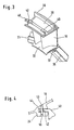
- eine perspektivische Ansicht des Bereichs der Leitschaufeln nach
Fig. 2 und - Fig. 4
- eine Einzelheit in vergrößerter Darstellung.
- Einen in
Fig. 1 nur im Übergangsbereich zwischen Hochdruckturbine HD und Niederdruckturbine ND schematisch dargestellte Fluggasturbine 10 ist von einem als Ringkanal ausgebildeten Strömungskanal 12 durchsetzt, der von dem kleinen Durchmesser des Hochdruckteils HD zum größeren Durchmesser des Niederdruckteils ND führt. Diese Überleitung erfolgt über einen Überleitungskanal 14, der stromab ein Kanalsegment 14a und stromauf ein eine Vielzahl von Leitschaufeln 15 haltendes besonders ausgebildetes Kanalsegment 14b umfasst, das nachfolgend als Leitschaufelsegment 16 bezeichnet ist. - Ein insgesamt mit der Bezugsziffer 18 bezeichnetes, in bekannter Weise aufgebautes Gehäuse umschließt Hoch- und Niederdruckteil der Turbine. Hier sind der im Kanalzwischenraum 22 befindliche Lagerträger 21 nahe der Dichtung 20 sowie die Lagerstellen 24, 35 und 38 von Interesse.
- Das die Leitschaufeln 15 tragende Leitschaufelsegment 16 weist einen nach außen - zur Innenwandung des Gehäuses 18 - gerichtete äußere Plattform 30 und eine innere der Rotationsachse 29 der Fluggasturbine zugewandte Plattform 32 auf - vgl. insbesondere
Fig. 3 -, die jeweils in Radialrichtung 34 sich erstreckende Stege 36 bzw. 37 tragen. Diesen Stegen sind Lagerflächen 38 bzw. 35 am Gehäuse 18 bzw. am Lagerträger 21 - vgl.Fig. 2 - zugeordnet, an dem sich die Stege im zusammengebauten Zustand der Fluggasturbine axial abstützen. - Die Plattform 30 weist ferner stromab hakenförmig entgegen der Axialrichtung 39 gebogene Vorsprünge 40 auf, von denen ein Vorsprung mit einem Schlitz 42 versehen ist, vgl.
Fig. 3 . Diesen Vorsprüngen 40 sind korrespondierende Nuten 44 zugeordnet, welche sich in den Lagerstellen 24 des Gehäuses 18 befinden; vgl. auchFig. 4 . Eine dieser Nuten ist mit einem dem Schlitz 42 zugeordneten Durchbruch 45 versehen zwecks Aufnahme eines Stiftes 46, wie dies ebenfalls ausFig. 4 deutlich erkennbar ist. - Die Nuten 44 im Zusammenwirken mit den hakenförmigen Vorsprüngen 40 bilden eine sogenannte Nut-Hakenverbindung, die ein formschlüssiges Fixieren des Leitschaufelsegmentes 16 im Turbinengehäuse ermöglicht, wobei mittels des Stiftes 46 dieses Segment auch gegen Verdrehen um die Rotationsachse 29 gesichert ist.
- Die Ausbildung der Stege 36 und 37 der äußeren und inneren Plattform 30 und 32 sowie der zugeordneten Lagerflächen an den gehäusefesten Lagerstellen 24 und dem Lagerträger 21 ist derart, dass jeweils gerade Flächenberührung zwischen diesen Flächen vorhanden ist, was eine betriebssichere Abdichtung an den Berührungsstellen und damit zu dem Scheibenraum der Niederdruckturbine ermöglicht.
- Nach dem Einbau des Leitschaufelsegmentes bildet dieses eine Verriegelung für das vorgelagerte Kanalsegment 14a, das über eine Strebenverkleidung 50 u. a. an den Lagerstellen 24 des Gehäuses 18 gelagert ist.
- Die vorstehend beschriebene Anordnung mit der Nut-Hakenverbindung ermöglicht also ein gewichts- und kostengünstiges sowie einfach zu handhabendes lösbares kraft- und formschlüssiges Einsetzen des Leitschaufeln aufweisenden Übergangkanals in den Scheibenraum zwischen Hoch- und Niederdruckteil der vorzugsweise als Zweiwellenturbine ausgebildeten Fluggasturbine. Die gerade Linienberührung zwischen den Stegen des Leitschaufelsegmentes und den zugeordneten Lagerflächen ermöglicht darüber hinaus ein einfaches Abdichten dieses Segmentes.
Claims (2)
- Anordnung zur Befestigung eines einen Teil eines Übergangskanals bildenden Leitschaufelsegmentes (16) zwischen Gehäuse (18) und Lagerträger (21) eines Turbinengehäuses einer eine Hoch- und eine Niederdruckturbine mit unterschiedlichen Durchmessern aufweisenden Fluggasturbine, vorzugsweise einer Zweiwellen-Fluggasturbine, deren Übergangskanal vom kleineren Durchmesser der Hochdruckturbine zum größeren Durchmesser der Niederdruckturbine überleitet, wobei das Leitschaufelsegment (16) eine äußere und eine innere, die Leitschaufeln (15) einspannende Plattform umfasst die Plattformen (30, 32) zur axialen Positionierung und Abdichtung des Leitschaufelsegments (16) Stege (36, 37) aufweisen, die jeweils eine gerade Flächenberührung mit Lagerflächen (35, 38) des Lagerträgers (21) und des Gehäuses (18) ermöglichen, das Leitschaufelsegment (16) mittels einer stromaufliegenden, der äußeren Plattform (30) zugeordneten Nut-Hakenverbindung (40,44) an dem Gehäuse (18) radial gehalten und dadurch gekennzeichnet, dass das Leitschaufelsegment (16) mittels eines in die Nut-Hakenverbindung eingreifenden Stiftes (46) gegen Verdrehen gesichert ist, und dass die Nuten (44) der Nut-Hakenverbindung Lagerstellen (24) des Gehäuses (18), die Haken (40) der äußeren Plattform (30) des Leitschaufelsegmentes (16) zugeordnet sind.
- Anordnung nach Anspruch 1, dadurch gekennzeichnet, dass die die Nuten (44) der Nut-Hakenverbindung aufweisenden Lagerstellen (24) des Gehäuses (18) gleichzeitig Lagerstellen für das vorgelagerte Kanalsegment (14a) des Übergangskanals (16) bilden, das in seiner Einbaulage durch das Leitschaufelsegment (16) verriegelt ist.
Applications Claiming Priority (3)
| Application Number | Priority Date | Filing Date | Title |
|---|---|---|---|
| DE10210866A DE10210866C5 (de) | 2002-03-12 | 2002-03-12 | Leitschaufelbefestigung in einem Strömungskanal einer Fluggasturbine |
| DE10210866 | 2002-03-12 | ||
| PCT/DE2003/000686 WO2003076768A1 (de) | 2002-03-12 | 2003-03-05 | Leitschaufelbefestigung in einem strömungskanal einer fluggasturbine |
Publications (2)
| Publication Number | Publication Date |
|---|---|
| EP1483482A1 EP1483482A1 (de) | 2004-12-08 |
| EP1483482B1 true EP1483482B1 (de) | 2008-08-20 |
Family
ID=27618826
Family Applications (1)
| Application Number | Title | Priority Date | Filing Date |
|---|---|---|---|
| EP03714672A Expired - Lifetime EP1483482B1 (de) | 2002-03-12 | 2003-03-05 | Leitschaufelbefestigung in einem strömungskanal einer fluggasturbine |
Country Status (4)
| Country | Link |
|---|---|
| US (1) | US7258525B2 (de) |
| EP (1) | EP1483482B1 (de) |
| DE (2) | DE10210866C5 (de) |
| WO (1) | WO2003076768A1 (de) |
Cited By (3)
| Publication number | Priority date | Publication date | Assignee | Title |
|---|---|---|---|---|
| US11098599B2 (en) | 2017-12-07 | 2021-08-24 | MTU Aero Engines AG | Flow channel for a turbomachine |
| US11396812B2 (en) | 2017-12-01 | 2022-07-26 | MTU Aero Engines AG | Flow channel for a turbomachine |
| EP4603677A1 (de) * | 2024-02-16 | 2025-08-20 | MTU Aero Engines AG | Leitschaufelsegment |
Families Citing this family (29)
| Publication number | Priority date | Publication date | Assignee | Title |
|---|---|---|---|---|
| DE102004036594A1 (de) * | 2004-07-28 | 2006-03-23 | Mtu Aero Engines Gmbh | Strömungsstruktur für eine Gasturbine |
| US7458772B2 (en) * | 2004-10-26 | 2008-12-02 | Alstom Technology Ltd. | Guide vane ring of a turbomachine and associated modification method |
| US7510371B2 (en) * | 2005-06-06 | 2009-03-31 | General Electric Company | Forward tilted turbine nozzle |
| US7594388B2 (en) * | 2005-06-06 | 2009-09-29 | General Electric Company | Counterrotating turbofan engine |
| US7513102B2 (en) | 2005-06-06 | 2009-04-07 | General Electric Company | Integrated counterrotating turbofan |
| ATE430874T1 (de) * | 2005-08-17 | 2009-05-15 | Alstom Technology Ltd | Leitschaufel-anordnung einer strömungsmaschine |
| US7762761B2 (en) * | 2005-11-30 | 2010-07-27 | General Electric Company | Methods and apparatus for assembling turbine nozzles |
| JP2011001950A (ja) * | 2009-05-19 | 2011-01-06 | Hitachi Ltd | 2軸式ガスタービン |
| CN102323962B (zh) * | 2011-05-20 | 2012-12-26 | 西北工业大学 | 航空发动机叶片型面流道线测量路径规划方法 |
| US9540955B2 (en) * | 2012-05-09 | 2017-01-10 | United Technologies Corporation | Stator assembly |
| FR2990719B1 (fr) * | 2012-05-16 | 2016-07-22 | Snecma | Distributeur de turbomachine, et procede de fabrication |
| US9334756B2 (en) * | 2012-09-28 | 2016-05-10 | United Technologies Corporation | Liner and method of assembly |
| US9670790B2 (en) * | 2012-09-28 | 2017-06-06 | United Technologies Corporation | Turbine vane with mistake reduction feature |
| EP2868868A1 (de) * | 2013-11-05 | 2015-05-06 | Siemens Aktiengesellschaft | Montagevorrichtung und Montageverfahren einer Leitschaufel |
| JP5717904B1 (ja) * | 2014-08-04 | 2015-05-13 | 三菱日立パワーシステムズ株式会社 | 静翼、ガスタービン、分割環、静翼の改造方法、および、分割環の改造方法 |
| US20160102580A1 (en) * | 2014-10-13 | 2016-04-14 | Pw Power Systems, Inc. | Power turbine inlet duct lip |
| US10378371B2 (en) * | 2014-12-18 | 2019-08-13 | United Technologies Corporation | Anti-rotation vane |
| CN107111084A (zh) | 2015-01-10 | 2017-08-29 | 镭亚股份有限公司 | 偏振混合光导及使用其的基于多波束光栅的背光 |
| JP6824171B2 (ja) | 2015-01-10 | 2021-02-10 | レイア、インコーポレイテッドLeia Inc. | 制御された回折カップリング効率を有する回折格子ベースの背面照明 |
| KR102214345B1 (ko) | 2015-01-10 | 2021-02-09 | 레이아 인코포레이티드 | 2차원/3차원(2d/3d) 전환가능 디스플레이 백라이트 및 전자 디스플레이 |
| KR102200059B1 (ko) | 2015-01-19 | 2021-01-08 | 레이아 인코포레이티드 | 반사 아일랜드를 채용하는 단일 방향 격자-기반 백라이팅 |
| JP6633087B2 (ja) | 2015-01-28 | 2020-01-22 | レイア、インコーポレイテッドLeia Inc. | 3次元(3d)電子ディスプレイ |
| CN107430240B (zh) | 2015-03-16 | 2020-09-18 | 镭亚股份有限公司 | 采用角度选择性反射层的基于单向光栅的背光 |
| CN107533255A (zh) | 2015-04-23 | 2018-01-02 | 镭亚股份有限公司 | 基于双光导光栅的背光以及使用该背光的电子显示器 |
| CN107624163B (zh) | 2015-05-09 | 2020-11-06 | 镭亚股份有限公司 | 基于颜色扫描光栅的背光体及使用该背光体的电子显示器 |
| US10450895B2 (en) * | 2016-04-22 | 2019-10-22 | United Technologies Corporation | Stator arrangement |
| KR101937586B1 (ko) * | 2017-09-12 | 2019-01-10 | 두산중공업 주식회사 | 베인 조립체, 터빈 및 이를 포함하는 가스터빈 |
| US20190218928A1 (en) * | 2018-01-17 | 2019-07-18 | United Technologies Corporation | Blade outer air seal for gas turbine engine |
| DE102023104051A1 (de) * | 2023-02-17 | 2024-08-22 | MTU Aero Engines AG | Statorvorrichtung zur Anordnung innerhalb eines vorgegebenen Turbinengehäuses einer Strömungsmaschine, Verbindungssystem für eine Strömungsmaschine, sowie Strömungsmaschine |
Family Cites Families (9)
| Publication number | Priority date | Publication date | Assignee | Title |
|---|---|---|---|---|
| GB589541A (en) * | 1941-09-22 | 1947-06-24 | Hayne Constant | Improvements in axial flow turbines, compressors and the like |
| US3443791A (en) * | 1966-11-23 | 1969-05-13 | United Aircraft Corp | Turbine vane assembly |
| GB1596255A (en) * | 1973-07-26 | 1981-08-26 | Rolls Royce | Stator blade for a gas turbine engine |
| DE3003470C2 (de) * | 1980-01-31 | 1982-02-25 | MTU Motoren- und Turbinen-Union München GmbH, 8000 München | Turbinenleitschaufelaufhängung für Gasturbinenstrahltriebwerke |
| US4511306A (en) * | 1982-02-02 | 1985-04-16 | Westinghouse Electric Corp. | Combustion turbine single airfoil stator vane structure |
| US4747750A (en) * | 1986-01-17 | 1988-05-31 | United Technologies Corporation | Transition duct seal |
| US5022818A (en) * | 1989-02-21 | 1991-06-11 | Westinghouse Electric Corp. | Compressor diaphragm assembly |
| US5176496A (en) * | 1991-09-27 | 1993-01-05 | General Electric Company | Mounting arrangements for turbine nozzles |
| US6183192B1 (en) * | 1999-03-22 | 2001-02-06 | General Electric Company | Durable turbine nozzle |
-
2002
- 2002-03-12 DE DE10210866A patent/DE10210866C5/de not_active Expired - Fee Related
-
2003
- 2003-03-05 EP EP03714672A patent/EP1483482B1/de not_active Expired - Lifetime
- 2003-03-05 DE DE50310362T patent/DE50310362D1/de not_active Expired - Lifetime
- 2003-03-05 WO PCT/DE2003/000686 patent/WO2003076768A1/de not_active Ceased
- 2003-03-05 US US10/507,176 patent/US7258525B2/en not_active Expired - Fee Related
Cited By (3)
| Publication number | Priority date | Publication date | Assignee | Title |
|---|---|---|---|---|
| US11396812B2 (en) | 2017-12-01 | 2022-07-26 | MTU Aero Engines AG | Flow channel for a turbomachine |
| US11098599B2 (en) | 2017-12-07 | 2021-08-24 | MTU Aero Engines AG | Flow channel for a turbomachine |
| EP4603677A1 (de) * | 2024-02-16 | 2025-08-20 | MTU Aero Engines AG | Leitschaufelsegment |
Also Published As
| Publication number | Publication date |
|---|---|
| US7258525B2 (en) | 2007-08-21 |
| US20060008347A1 (en) | 2006-01-12 |
| DE50310362D1 (de) | 2008-10-02 |
| EP1483482A1 (de) | 2004-12-08 |
| WO2003076768A1 (de) | 2003-09-18 |
| DE10210866C1 (de) | 2003-08-21 |
| DE10210866C5 (de) | 2008-04-10 |
Similar Documents
| Publication | Publication Date | Title |
|---|---|---|
| EP1483482B1 (de) | Leitschaufelbefestigung in einem strömungskanal einer fluggasturbine | |
| EP1148209B1 (de) | Zwischenstufendichtungsanordnung | |
| EP1898054B1 (de) | Gasturbine | |
| EP2918913B1 (de) | Brennkammer einer Gasturbine mit äusserer und innerer Brennkammerwand | |
| EP0834645B1 (de) | Verdichterradbefestigung für Turbolader | |
| EP2527253B1 (de) | Enteisungsvorrichtung eines Flugzeuggasturbinentriebwerks | |
| EP3287611B1 (de) | Gasturbine | |
| EP1460237A1 (de) | Abgasturbinengehäuse | |
| EP3524781B1 (de) | Verbindungseinrichtung für eine verstellbare schaufel einer gasturbine | |
| EP2806107B1 (de) | Geteilter Innenring | |
| EP2268902B1 (de) | Strebe für ein turbinenzwischengehäuse und turbinenzwischengehäuse | |
| EP2818724B1 (de) | Strömungsmaschine und Verfahren | |
| WO2010063525A1 (de) | Leitschaufelanordnung für eine axialturbomaschine | |
| DE102007050916A1 (de) | Verfahren und Vorrichtung zum Zusammenbau von Gasturbinen-Triebwerken | |
| EP2871325B1 (de) | Innenring einer Strömungsmaschine und Leitrad | |
| EP2591213B1 (de) | Verdichter und zugehörige gasturbine | |
| EP3176386B1 (de) | Innenringsystem, zugehöriger innenring, zwichengehäuse und strömungsmaschine | |
| EP0999349A2 (de) | Axialturbine | |
| EP3287608B1 (de) | Innenring für einen leitschaufelkranz einer strömungsmaschine | |
| EP3379037B1 (de) | Dichtung am innenring eines leitschaufelkranzes | |
| EP3309360B1 (de) | Laufschaufelbaugruppe für ein triebwerk | |
| EP3309359B1 (de) | Laufschaufelbaugruppe für ein triebwerk | |
| EP2250348B1 (de) | Befestigungsvorrichtung für einen abgasturbolader | |
| EP1860284A1 (de) | Gehäuseverbindung | |
| EP3327258A1 (de) | Eintrittsleitrad für eine turbomaschine |
Legal Events
| Date | Code | Title | Description |
|---|---|---|---|
| PUAI | Public reference made under article 153(3) epc to a published international application that has entered the european phase |
Free format text: ORIGINAL CODE: 0009012 |
|
| 17P | Request for examination filed |
Effective date: 20040827 |
|
| AK | Designated contracting states |
Kind code of ref document: A1 Designated state(s): AT BE BG CH CY CZ DE DK EE ES FI FR GB GR HU IE IT LI LU MC NL PT RO SE SI SK TR |
|
| GRAP | Despatch of communication of intention to grant a patent |
Free format text: ORIGINAL CODE: EPIDOSNIGR1 |
|
| GRAC | Information related to communication of intention to grant a patent modified |
Free format text: ORIGINAL CODE: EPIDOSCIGR1 |
|
| GRAS | Grant fee paid |
Free format text: ORIGINAL CODE: EPIDOSNIGR3 |
|
| GRAA | (expected) grant |
Free format text: ORIGINAL CODE: 0009210 |
|
| AK | Designated contracting states |
Kind code of ref document: B1 Designated state(s): DE FR GB |
|
| REG | Reference to a national code |
Ref country code: GB Ref legal event code: FG4D Free format text: NOT ENGLISH |
|
| REF | Corresponds to: |
Ref document number: 50310362 Country of ref document: DE Date of ref document: 20081002 Kind code of ref document: P |
|
| PLBI | Opposition filed |
Free format text: ORIGINAL CODE: 0009260 |
|
| PLAX | Notice of opposition and request to file observation + time limit sent |
Free format text: ORIGINAL CODE: EPIDOSNOBS2 |
|
| 26 | Opposition filed |
Opponent name: ROLLS-ROYCE DEUTSCHLAND LTD & CO KG Effective date: 20090518 |
|
| PLAF | Information modified related to communication of a notice of opposition and request to file observations + time limit |
Free format text: ORIGINAL CODE: EPIDOSCOBS2 |
|
| PLBB | Reply of patent proprietor to notice(s) of opposition received |
Free format text: ORIGINAL CODE: EPIDOSNOBS3 |
|
| PLAB | Opposition data, opponent's data or that of the opponent's representative modified |
Free format text: ORIGINAL CODE: 0009299OPPO |
|
| R26 | Opposition filed (corrected) |
Opponent name: ROLLS-ROYCE DEUTSCHLAND LTD & CO KG Effective date: 20090518 |
|
| PGFP | Annual fee paid to national office [announced via postgrant information from national office to epo] |
Ref country code: FR Payment date: 20130329 Year of fee payment: 11 Ref country code: GB Payment date: 20130318 Year of fee payment: 11 Ref country code: DE Payment date: 20130320 Year of fee payment: 11 |
|
| REG | Reference to a national code |
Ref country code: DE Ref legal event code: R119 Ref document number: 50310362 Country of ref document: DE |
|
| RAP2 | Party data changed (patent owner data changed or rights of a patent transferred) |
Owner name: MTU AERO ENGINES GMBH |
|
| GBPC | Gb: european patent ceased through non-payment of renewal fee |
Effective date: 20140305 |
|
| REG | Reference to a national code |
Ref country code: FR Ref legal event code: ST Effective date: 20141128 |
|
| REG | Reference to a national code |
Ref country code: DE Ref legal event code: R119 Ref document number: 50310362 Country of ref document: DE Effective date: 20141001 |
|
| PG25 | Lapsed in a contracting state [announced via postgrant information from national office to epo] |
Ref country code: DE Free format text: LAPSE BECAUSE OF NON-PAYMENT OF DUE FEES Effective date: 20141001 Ref country code: GB Free format text: LAPSE BECAUSE OF NON-PAYMENT OF DUE FEES Effective date: 20140305 Ref country code: FR Free format text: LAPSE BECAUSE OF NON-PAYMENT OF DUE FEES Effective date: 20140331 |
|
| PLBD | Termination of opposition procedure: decision despatched |
Free format text: ORIGINAL CODE: EPIDOSNOPC1 |
|
| PLBM | Termination of opposition procedure: date of legal effect published |
Free format text: ORIGINAL CODE: 0009276 |
|
| STAA | Information on the status of an ep patent application or granted ep patent |
Free format text: STATUS: OPPOSITION PROCEDURE CLOSED |
|
| 27C | Opposition proceedings terminated |
Effective date: 20150711 |