EP1483523B1 - Anschlusskupplung mit schalteinheit - Google Patents
Anschlusskupplung mit schalteinheit Download PDFInfo
- Publication number
- EP1483523B1 EP1483523B1 EP03706596A EP03706596A EP1483523B1 EP 1483523 B1 EP1483523 B1 EP 1483523B1 EP 03706596 A EP03706596 A EP 03706596A EP 03706596 A EP03706596 A EP 03706596A EP 1483523 B1 EP1483523 B1 EP 1483523B1
- Authority
- EP
- European Patent Office
- Prior art keywords
- connecting coupling
- connection
- coupling
- coupling according
- eccentric shaft
- Prior art date
- Legal status (The legal status is an assumption and is not a legal conclusion. Google has not performed a legal analysis and makes no representation as to the accuracy of the status listed.)
- Expired - Lifetime
Links
- 230000008878 coupling Effects 0.000 title claims description 44
- 238000010168 coupling process Methods 0.000 title claims description 44
- 238000005859 coupling reaction Methods 0.000 title claims description 44
- 239000012530 fluid Substances 0.000 claims description 16
- 239000007788 liquid Substances 0.000 claims description 3
- 238000009423 ventilation Methods 0.000 claims 2
- 238000007789 sealing Methods 0.000 description 17
- 210000002445 nipple Anatomy 0.000 description 14
- 230000006835 compression Effects 0.000 description 4
- 238000007906 compression Methods 0.000 description 4
- 230000005540 biological transmission Effects 0.000 description 2
- 238000010276 construction Methods 0.000 description 2
- 238000000034 method Methods 0.000 description 2
- 230000006978 adaptation Effects 0.000 description 1
- 230000001419 dependent effect Effects 0.000 description 1
- 238000011161 development Methods 0.000 description 1
- 230000018109 developmental process Effects 0.000 description 1
- 238000006073 displacement reaction Methods 0.000 description 1
- 239000000463 material Substances 0.000 description 1
- 230000000284 resting effect Effects 0.000 description 1
- 238000013022 venting Methods 0.000 description 1
Images
Classifications
-
- F—MECHANICAL ENGINEERING; LIGHTING; HEATING; WEAPONS; BLASTING
- F16—ENGINEERING ELEMENTS AND UNITS; GENERAL MEASURES FOR PRODUCING AND MAINTAINING EFFECTIVE FUNCTIONING OF MACHINES OR INSTALLATIONS; THERMAL INSULATION IN GENERAL
- F16L—PIPES; JOINTS OR FITTINGS FOR PIPES; SUPPORTS FOR PIPES, CABLES OR PROTECTIVE TUBING; MEANS FOR THERMAL INSULATION IN GENERAL
- F16L37/00—Couplings of the quick-acting type
- F16L37/28—Couplings of the quick-acting type with fluid cut-off means
- F16L37/30—Couplings of the quick-acting type with fluid cut-off means with fluid cut-off means in each of two pipe-end fittings
- F16L37/36—Couplings of the quick-acting type with fluid cut-off means with fluid cut-off means in each of two pipe-end fittings with two lift valves being actuated to initiate the flow through the coupling after the two coupling parts are locked against withdrawal
-
- F—MECHANICAL ENGINEERING; LIGHTING; HEATING; WEAPONS; BLASTING
- F17—STORING OR DISTRIBUTING GASES OR LIQUIDS
- F17C—VESSELS FOR CONTAINING OR STORING COMPRESSED, LIQUEFIED OR SOLIDIFIED GASES; FIXED-CAPACITY GAS-HOLDERS; FILLING VESSELS WITH, OR DISCHARGING FROM VESSELS, COMPRESSED, LIQUEFIED, OR SOLIDIFIED GASES
- F17C2205/00—Vessel construction, in particular mounting arrangements, attachments or identifications means
- F17C2205/03—Fluid connections, filters, valves, closure means or other attachments
- F17C2205/0302—Fittings, valves, filters, or components in connection with the gas storage device
- F17C2205/037—Quick connecting means, e.g. couplings
-
- Y—GENERAL TAGGING OF NEW TECHNOLOGICAL DEVELOPMENTS; GENERAL TAGGING OF CROSS-SECTIONAL TECHNOLOGIES SPANNING OVER SEVERAL SECTIONS OF THE IPC; TECHNICAL SUBJECTS COVERED BY FORMER USPC CROSS-REFERENCE ART COLLECTIONS [XRACs] AND DIGESTS
- Y10—TECHNICAL SUBJECTS COVERED BY FORMER USPC
- Y10T—TECHNICAL SUBJECTS COVERED BY FORMER US CLASSIFICATION
- Y10T137/00—Fluid handling
- Y10T137/8593—Systems
- Y10T137/87917—Flow path with serial valves and/or closures
- Y10T137/87925—Separable flow path section, valve or closure in each
- Y10T137/87941—Each valve and/or closure operated by coupling motion
- Y10T137/87949—Linear motion of flow path sections operates both
-
- Y—GENERAL TAGGING OF NEW TECHNOLOGICAL DEVELOPMENTS; GENERAL TAGGING OF CROSS-SECTIONAL TECHNOLOGIES SPANNING OVER SEVERAL SECTIONS OF THE IPC; TECHNICAL SUBJECTS COVERED BY FORMER USPC CROSS-REFERENCE ART COLLECTIONS [XRACs] AND DIGESTS
- Y10—TECHNICAL SUBJECTS COVERED BY FORMER USPC
- Y10T—TECHNICAL SUBJECTS COVERED BY FORMER US CLASSIFICATION
- Y10T137/00—Fluid handling
- Y10T137/8593—Systems
- Y10T137/87917—Flow path with serial valves and/or closures
- Y10T137/87981—Common actuator
Definitions
- the invention relates to a connection coupling for the transmission of gaseous and / or liquid fluids, in particular for filling vehicle gas tanks.
- connection couplings With such connection couplings, a secure and quickly connectable transmission of a fluid from a pressure source, for example, from a refueling system to a vehicle to be achieved. Particularly important here is the simple and safe operation, so that even at high refueling pressures of 200 bar (20 MPa) and more trouble-free handling is possible.
- US-A-4,212,411 describes a connection coupling, which includes all the features of the preamble of claim 1.
- connection coupling is also in the WO 98/05898 the applicant described, wherein the quick-connect coupling comprises a housing having a fluid inlet and a fluid outlet, and a plurality of valves are provided to ensure a secure seal of the quick-connect coupling until complete connection.
- These valves are switched after applying the quick-connect coupling by turning a control lever in a certain predetermined order, first by the sliding of the quick-release coupling to a nipple the exhaust valve is opened, then upon further movement of the control lever serving as locking elements collets are closed and finally the Inlet valve is opened.
- the control lever is in this case via an eccentric shaft with the sliding sleeve for the application of the collets and with a sealing piston in engagement, which also releases the fluid inlet after the connection of the plug-in coupling.
- control lever By twisting the connection hoses, the control lever can assume an unfavorable position (eg to the right), which is extremely uncomfortable for a left-hander when operating the connection coupling.
- connection coupling has been proven by its particularly secure connection option, it is still able to be improved in terms of handling.
- the invention has for its object to provide a connection coupling, in particular as a quick-release coupling of the type mentioned above, which allows a particularly simple handling with a compact design.
- connection coupling is particularly suitable for use in a quick connection coupling for refueling Erdgasfahreugen, resulting in a particularly simple and compact design, since the control lever is formed together with the switching unit around the central axis rotatable and thus assume during the connection process each desired by the operator rotational position can.
- the switching unit can be rotated in a preferred embodiment by the opposing annular slide in a suitable position for the operator, resulting in a particularly safe and convenient handling.
- connection coupling By integrated within the connection passage through slots in the middle housing part a secure guidance of the switching unit is achieved and thus achieves a stable and compact construction of the connection coupling. Since the switching unit is outside the pressure range, a simple and smooth handling is ensured, so that the quick-connect coupling can be easily connected even by laymen.
- a vent hole is preferably provided in the housing of the switching unit. This one will preferably closed with a sintered filter or a similar material, wherein a dirt entry is avoided.
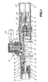
- connection coupling 10 in the form of a so-called.
- Quick connection coupling shown, which is coupled to a here indicated on the left connecting nipple 30.
- the connection coupling 10 has a tubular housing 11 with a plurality of housing parts 11a, 11b and 11c screwed together, the right housing part 11c serving as the inlet area 12 and the left area as the outlet 13 for the forwarding of the fluid to be transferred to the connection nipple 30.
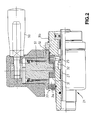
- a switching unit 21 with control lever 50 is arranged around the middle housing part 11b (cf. Fig. 2 ).
- the inlet region 12 has a connection adapter 14 to which a fluid line 12 'for supplying the fluid to be transferred can be connected via a thread.
- the connection adapter 14 with a filter sleeve inserted can be designed accordingly in adaptation to the fluid to be transferred, in particular to the respective desired Zurioshong, passage cross sections, etc.
- a plurality of elongated collets 15, which are arranged in the form of tubes, are provided, which can be spread radially outward shortly before being placed on the connecting nipple 30.
- the elongated collets 15 are - as by the aforementioned prior art known - biased by an annular spring 16, so that the collets 15 are radially spread outwards.
- the collets 15 At the here left outer end with inwardly cranked surfaces, the collets 15 each corresponding to a groove-shaped connection profile of the connecting nipple 30 formed positive engagement profiles 17.
- Their construction is also described in detail in the aforementioned prior art, so that it is possible to dispense with a further explanation here.
- a discharge valve forming sealing piston 22 which has at its front end face a conical sealing surface 23 for engagement with a sealing ring of the connecting nipple 30, so that the substantially along the central axis of the Coupling 10 flowing gaseous and / or liquid fluid can not escape to the outside.
- the provided on the sealing piston 22 outlet valve 25 seals by means of a sealing ring as a valve seat 26 relative to the sealing piston 22 in the closed position.
- the outlet valve 25 is acted upon by a compression spring 28, which is supported on the right side towards a slide valve 27 of the switching unit 21.
- the slide switch 27 is when uncoupling the connection coupling 10 from the connection nipple 30 through the switching unit 21 along the Coupling axis shifted and thus forms together with a sealing washer 24 a vent valve 35th
- vent valve 35 and the slide switch 27 are in this case actuated by pivoting the control lever 50, since the associated, mounted in a sleeve 52 eccentric shaft 51 is coupled to the slide switch 27, namely by engagement of a plurality of bolts 29 which are slidably inserted into axial slots 32 and with an outer annular slide 31 in conjunction.
- This has an annular groove, in which engages the lower end of the eccentric shaft 51 here.
- the entire switching unit 21 with the control lever 50 is rotatable about this annular slide 31, since the sleeve 52 is rotatably mounted on the outer circumference of the central housing part 11b.
- connection position of the connection coupling 10 shown here the engagement profile 17 of the collets 15 is brought into engagement with the connection nipple 30 when plugged onto the connection nipple 30.
- the sliding sleeve 18 is pushed over the collets 15 and this thus locked.
- pressurization beginning of refueling process
- the sealing piston 22 is first moved (also under the action of the spring 28) to the left.
- the valve seat 26 on the sealing piston 22 and thus the outlet valve 25 are also opened with displacement of the sealing piston 22 to the right.
- the engagement profile 17 has already intervened on the correspondingly formed connection profile of the connecting nipple 30, wherein the axial movement of the sliding sleeve 18 engages over the radially outer ends of the collets 15, so that they are held in a form-fitting manner at the connection nipple 30.
- the sliding sleeve 18 after turning the control lever 50 of the compression spring 19 pushed back. After a short distance, the collets 15 can again spread radially outward.
- the sealing piston 22 since the fluid pressure has been interrupted (eg by closing a refueling valve), the sealing piston 22 is here shifted to the right in the direction of the inlet region 12, and the outlet valve 25 is closed at the valve seat 26.
- an inlet valve 45 is further arranged with an associated valve seat 46 centrally in the housing 11 and the housing part 11c of the connection coupling 10.
- the inlet valve 45 is also axially displaceable by the control lever 50 and its eccentric shaft 51 by the coupling with the slide valve 27.
- This slide valve 27 moves namely on the sealing disk 24 in the connection position shown a valve spool 47 of the inlet valve 45 in the open position, so that the inflowing from the inlet portion 12 fluid through the valve spool 47 and a passage in the sealing washer 24 and the tubular slide valve 27 to the outlet 13th can flow.
- connection coupling 10 When loosening the connecting coupling 10 (by about 180 °) of the switching slide 27 is moved over the bolts 29 to the left by turning the control lever 50, so that the sealing washer 24 can be released from the sealing engagement. In this case, the pressure within the connection coupling 10 can be reduced via passage slots 36 to a pressure equalization chamber 44.
- venting valve 35 is thus opened by the eccentric shaft 51 and the slide switch 27 when uncoupling the connection coupling 10.
- This still pending pressure medium flows through the pressure compensation chamber 44 to a vent hole 43 which extends parallel to the central fluid passage (through the valves 45, 35 and 25) in the housing part 11c of the connection coupling 10.
- the vent hole 43 opens into the second conduit 12 ", which is preferably designed as a return hose and as well the supply line is bounded by a housing cap 48 to serve as a handle for easy handling.
- the vent line 12 "and the adapter 14 connected to the fluid line 12 'thus always at least substantially parallel to each other.
- Fig. 2 the switching unit 21 is shown enlarged, wherein in the sleeve 52 for a possible pressure reduction nor a vent hole 33 is provided.
- a filter disk 34 in particular a sintered filter and is opposite to the annular slide 31 in the axial direction, which is movable by means of the eccentric shaft 51 in the axial direction and thereby axially displaces the inner slide valve 27 by a few centimeters on the Bolzem 29, as far as through the Length of the axial slots 32 is possible.
Landscapes
- Engineering & Computer Science (AREA)
- General Engineering & Computer Science (AREA)
- Mechanical Engineering (AREA)
- Quick-Acting Or Multi-Walled Pipe Joints (AREA)
- Filling Or Discharging Of Gas Storage Vessels (AREA)
- Loading And Unloading Of Fuel Tanks Or Ships (AREA)
Description
- Die Erfindung betrifft eine Anschlußkupplung für die Übertragung von gasförmigen und/oder flüssigen Fluiden, insbesondere zum Befüllen von Fahrzeug-Gastanks.
- Mit derartigen Anschlußkupplungen soll eine sichere und schnell anschließbare Übertragung eines Fluids von einer Druckquelle, beispielsweise von einer Betankungsanlage aus zu einem Fahrzeug erreicht werden. Besonders wichtig ist hierbei die einfache und sichere Bedienbarkeit, so daß auch bei hohen Betankungsdrücken von 200 bar (20MPa) und mehr eine problemlose Handhabung möglich ist.
US-A-4 212 411 beschreibt eine Anschlusskupplung, die alle Merkmale des Oberbegriffs des Anspruchs 1 beinhaltet. - Eine Anschlußkupplung ist auch in der
WO 98/05898 - Durch Tordierung der Anschlußschläuche kann der Steuerungshebel dabei eine ungünstige Stellung (z. B. nach rechts hin) einnehmen, was für einen Linkshänder beim Bedienen der Anschlußkupplung äußerst unbequem ist.
- Obwohl sich die bekannte Anschlußkupplung durch ihre besonders sichere Anschlußmöglichkeit bewährt hat, ist sie hinsichtlich ihrer Handhabung noch verbesserungsfähig.
- Demzufolge liegt der Erfindung die Aufgabe zugrunde, eine Anschlußkupplung, insbesondere als Schnellanschlußkupplung der eingangs genannten Art zu schaffen, die bei kompaktem Aufbau eine besonders einfache Handhabung ermöglicht.
- Diese Aufgabe wird gelöst durch eine Anschlußkupplung gemäß den Merkmalen des Anspruches 1. Bevorzugte Weiterbildungen der Erfindung sind Gegenstand der Unteransprüche.
- Die vorgeschlagene Anschlußkupplung eignet sich insbesondere für den Einsatz bei einer Schnellanschlußkupplung zur Betankung von Erdgasfahreugen, wobei sich eine besonders einfache und kompakte Bauweise ergibt, da der Steuerungshebel mitsamt der Schalteinheit um die Zentralachse herum drehbar ausgebildet ist und somit beim Anschlußvorgang jede vom Bediener gewünschte Verdrehstellung einnehmen kann. Insbesondere kann die Schalteinheit in bevorzugter Ausführungsform durch die einander gegenüberliegenden Ringschieber in eine für die Bedienperson passende Stellung verdreht werden, was eine besonders sichere und bequeme Handhabung ergibt.
- Durch innerhalb der Anschlußkupplung integrierte Durchtrittsschlitze im mittleren Gehäuseteil wird eine sichere Führung der Schalteinheit erreicht und somit ein stabiler und kompakter Aufbau der Anschlußkupplung erzielt. Da sich die Schalteinheit außerhalb des Druckbereiches befindet, wird eine einfache und leichtgängige Handhabbarkeit gewährleistet, so dass die Schnellanschlußkupplung auch von Laien problemlos angeschlossen werden kann.
- Um bei einer eventuell auftretenden Undichtigkeit einer Dichtung keinen Druckaufbau zuzulassen, ist im Gehäuse der Schalteinheit bevorzugt eine Entlüftungsbohrung vorgesehen. Diese wird bevorzugt mit einem Sinterfilter oder einem ähnlichen Material verschlossen, wobei ein Schmutzeintritt vermieden wird.
- Nachfolgend wird ein Ausführungsbeispiel anhand der beiliegenden Zeichnung näher erläutert und beschrieben. Hierin zeigt:
- Fig. 1
- eine Seitenansicht einer Anschlußkupplung mit einer integrierten Schalteinheit, wobei die Anschlußkupplung im Längs-Halbschnitt und in angeschlossener Stellung an einen Anschlußnippel dargestellt ist; und
- Fig. 2
- eine vergrößerte Darstellung der Schalteinheit der Anschlußkupplung gemäß
Fig. 1 . - In
Fig. 1 ist ein bevorzugtes Ausführungsbeispiel einer Anschlußkupplung 10 in Form einer sog. Schnellanschlußkupplung dargestellt, die an einen hier links angedeuteten Anschlußnippel 30 angekuppelt ist. Die Anschlußkupplung 10 weist ein rohrförmiges Gehäuse 11 mit mehreren, miteinander verschraubten Gehäuseteilen 11a, 11b und 11c auf, wobei das hier rechte Gehäuseteil 11c als Einlaßbereich 12 dient und der linke Bereich als Auslaß 13 für die Weiterleitung des zu übertragenden Fluids an den Anschlußnippel 30. Um den mittleren Gehäuseteil 11b herum ist eine Schalteinheit 21 mit Steuerungshebel 50 angeordnet (vgl. auchFig. 2 ). Der Einlaßbereich 12 weist einen Anschlußadapter 14 auf, an den über ein Gewinde eine Fluidleitung 12' zur Zuführung des zu übertragenden Fluids angeschlossen werden kann. Der Anschlußadapter 14 mit einer eingesetzten Filterhülse kann hierbei in Anpassung an das zu übertragende Fluid, insbesondere an die jeweils gewünschten Zuführdruckwerte, Durchlaßquerschnitte usw. entsprechend gestaltet sein. - Im Bereich des Auslasses 13 sind mehrere, in Rohrform angeordnete, längliche Spannzangen 15 vorgesehen, die kurz vor dem Aufstecken auf den Anschlußnippel 30 radial nach außen aufgespreizt werden können. Die länglichen Spannzangen 15 sind dabei - wie durch den eingangs genannten Stand der Technik bekannt - durch eine Ringfeder 16 vorgespannt, so dass die Spannzangen 15 radial nach außen aufspreizbar sind. An dem hier linken äußeren Ende mit nach innen abgekröpften Flächen weisen die Spannzangen 15 jeweils korrespondierend zu einem nutförmigen Anschlußprofil des Anschlußnippels 30 ausgebildete formschlüssige Eingriffsprofile 17 auf. Deren Aufbau ist im eingangs genannten Stand der Technik ebenfalls näher beschrieben, so dass hier auf eine weitere Erläuterung verzichtet werden kann. Es sei lediglich noch erwähnt, dass im Bereich des Auslasses 13 innen ein das Auslaßventil bildender Dichtkolben 22 geführt ist, der an seiner vorderen stirnseite eine konische Dichtfläche 23 zur Anlage an einem Dichtring des Anschlußnippels 30 aufweist, so dass das im wesentlichen entlang der Zentralachse der Anschlußkupplung 10 strömende gasförmige und/oder flüssige Fluid nicht nach außen hin austreten kann.
- Um die Spannzangen 15 herum ist eine äußere Schiebehülse 18 vorgesehen, die an dem zylindrischen Außenmantel des hier linken Gehäuseteils 11a geführt ist und mit einer Druckfeder 19 in Richtung vom Anschlußnippel 30 weg vorgespannt ist. Die Druckfeder 19 stützt sich hierbei an einen Abstützring 20 ab und schiebt somit die Schiebehülse 18 zu dem Steuerungshebel 50 mit einer Exzenterwelle 51 hin, deren Aufbau nachfolgend noch näher beschrieben wird, insbesondere mit Bezug auf
Fig. 2 . - Das am Dichtkolben 22 vorgesehene Auslaßventil 25 dichtet mittels eines Dichtringes als Ventilsitz 26 gegenüber dem Dichtkolben 22 in geschlossener Stellung ab. Das Auslaßventil 25 ist hierbei von einer Druckfeder 28 beaufschlagt, die sich zur rechten Seite hin auf einen Schaltschieber 27 der Schalteinheit 21 abstützt. Durch dieses Auslaßventil 25 wird sichergestellt, dass in der hier nicht dargestellten abgekuppelten Position bzw. bis kurz vor dem Anschluß der Anschlußkupplung 10 an den Anschlußnippel 30 das durch den Anschlußadapter 14 zugeführte Fluid nicht ausströmen kann. Der Schaltschieber 27 wird beim Abkuppeln der Anschlußkupplung 10 vom Anschlußnippel 30 durch die Schalteinheit 21 entlang der Anschlußkupplungs-Achse verschoben und bildet so zusammen mit einer Dichtscheibe 24 ein Entlüftungsventil 35.
- Das Entlüftungsventil 35 und der Schaltschieber 27 werden hierbei durch Verschwenken des Steuerungshebels 50 betätigt, da die damit verbundene, in einer Hülse 52 gelagerte Exzenterwelle 51 mit dem Schaltschieber 27 gekoppelt ist, nämlich durch Eingriff mehrerer Bolzen 29, die in Axialschlitzen 32 verschiebbar eingesetzt sind und mit einem äußeren Ringschieber 31 in Verbindung stehen. Dieser weist eine Ringnut auf, in die das hier untere Ende der Exzenterwelle 51 eingreift. Dabei ist die gesamte Schalteinheit 21 mit dem Steuerungshebel 50 um diesen Ringschieber 31 herum drehbar, da die Hülse 52 am Außenumfang des mittleren Gehäuseteils 11b drehbar gelagert ist.
- Wie aus der hier dargestellten Anschlußstellung der Anschlußkupplung 10 ersichtlich ist, wird beim Aufstecken auf den Anschlußnippel 30 das Eingriffsprofil 17 der Spannzangen 15 mit dem Anschlußnippel 30 in Eingriff gebracht. Durch Betätigung (Verschwenken um ca. 180°) des Steuerungshebels 50 in die hier gezeigte Position wird die Schiebehülse 18 über die Spannzangen 15 geschoben und diese somit verriegelt. Bei Druckbeaufschlagung (Beginn des Betankungsvorganges) wird der Dichtkolben 22 zunächst (auch unter Wirkung der Feder 28) nach links verschoben. Bei Anlage an der Dichtfläche 23 wird unter Verschiebung des Dichtkolbens 22 nach rechts zudem der Ventilsitz 26 am Dichtkolben 22 und damit das Auslaßventil 25 geöffnet. Dabei hat das Eingriffsprofil 17 an dem korrespondierend ausgebildeten Anschlußprofil des Anschlußnippels 30 bereits eingegriffen, wobei durch die Axialbewegung der Schiebehülse 18 diese über die radial äußeren Enden der Spannzangen 15 greift, so dass diese am Anschlußnippel 30 formschlüssig gehalten werden.
- Zum Lösen der Anschlußkupplung 10 und damit dem Zurückführen der hier dargestellten Anschlußstellung in die Öffnungsstellung wird die Schiebehülse 18 nach Verdrehen des Steuerungshebels 50 von der Druckfeder 19 zurückgeschoben. Nach einem kurzen Weg können die Spannzangen 15 sich wieder radial nach außen aufspreizen. Da vorher der Fluiddruck unterbrochen wurde (z. B. durch Schließen eines Betankungsventils), wird zudem der Dichtkolben 22 hier nach rechts in Richtung zum Einlaßbereich 12 hin verschoben, sowie das Auslaßventil 25 am Ventilsitz 26 geschlossen.
- Im Einlaßbereich 12 ist weiterhin ein Einlaßventil 45 mit einem zugeordneten Ventilsitz 46 zentral im Gehäuse 11 bzw. dem Gehäuseteil 11c der Anschlußkupplung 10 angeordnet. Das Einlaßventil 45 ist ebenfalls durch den Steuerungshebel 50 und seine Exzenterwelle 51 durch die Koppelung mit dem Schaltschieber 27 axial verschiebbar. Dieser Schaltschieber 27 verschiebt nämlich über die Dichtscheibe 24 in der gezeigten Anschlußstellung einen Ventilschieber 47 des Einlaßventils 45 in die Öffnungsstellung, so dass das vom Einlaßbereich 12 zuströmende Fluid durch den Ventilschieber 47 und einen Durchlaß in der Dichtscheibe 24 sowie den rohrförmigen Schaltschieber 27 zum Auslaß 13 hin fließen kann.
- Beim Lösen der Anschlußkupplung 10 wird durch Verdrehen des Steuerungshebels 50 (um ca. 180°) der Schaltschieber 27 über die Bolzen 29 nach links verschoben, so dass sich auch die Dichtscheibe 24 aus dem Dichteingriff lösen kann. Hierbei kann sich der Druck innerhalb der Anschlußkupplung 10 über Durchtrittschlitze 36 zu einem Druckausgleichsraum 44 hin abbauen.
- Wie oben erwähnt, wird somit beim Abkuppeln der Anschlußkupplung 10 das Entlüftungsventil 35 durch die Exzenterwelle 51 und den Schaltschieber 27 geöffnet. Hierdurch strömt noch anstehendes Druckmedium über den Druckausgleichsraum 44 zu einer Entlüftungsbohrung 43, die parallel zu der zentralen Fluidpassage (durch die Ventile 45, 35 und 25 hindurch) im Gehäuseteil 11c der Anschlußkupplung 10 verläuft. Die Entlüftungsbohrung 43 mündet in der zweiten Leitung 12", die bevorzugt als Rückführschlauch ausgebildet ist und ebenso wie die Zuführleitung von einer Gehäusekappe 48 umgrenzt ist, um als Handgriff für eine einfache Handhabung dienen zu können. Die Entlüftungsleitung 12 " und die am Adapter 14 angeschlossene Fluidleitung 12' verlaufen somit immer zumindest weitgehend parallel zueinander.
- In
Fig. 2 ist die Schalteinheit 21 vergrößert dargestellt, wobei in der Hülse 52 für einen eventuellen Druckabbau noch eine Entlüftungsbohrung 33 vorgesehen ist. Diese ist mit einer Filterscheibe 34, insbesondere einem Sinterfilter abgeschlossen und liegt in Axialrichtung dem Ringschieber 31 gegenüber, der mittels der Exzenterwelle 51 in Axialrichtung beweglich ist und dabei über die Bolzem 29 den inneren Schaltschieber 27 ebenfalls um einige Zentimeter axial verschiebt, soweit dies durch die Länge der Axialschlitze 32 möglich ist.
Claims (6)
- Anschlusskupplung für die Übertragung von gasförmigen und/oder flüssigen Fluiden, insbesondere zum Befüllen von Fahrzeug- Gastanks, mit einer Schalteinheit (21) zur Betätigung von Ventilen (35) über einen Schaltschieber (27), wobei der Schaltschieber (27) durch wenigstens einen Bolzen (29) mit einem äußeren Ringschieber (31) gekoppelt ist,
dadurch gekennzeichnet, dass
die Schalteinheit (21) einen Steuerungshebel (50) und eine Exzenterwelle (51) aufweist, wobei die Exzenterwelle (51) in eine umlaufende Ringnut am Ringschieber (31) eingreift und die Exzenterwelle (51) in einer Hülse (52) gelagert ist, die am Umfang des mittleren Gehäuseteils (11b) um 360° drehbar gelagert ist. - Anschlusskupplung nach Anspruch 1, dadurch gekennzeichnet, dass zwischen Schaltschieber (27) und dem äußeren Ringschieber (31) mehrere Bolzen (29), insbesondere vier, vorgesehen sind.
- Anschlusskupplung nach Anspruch 2, dadurch gekennzeichnet, dass die Bolzen (29) in Axialschlitzen (32) im mittleren Gehäuseteil (11 b) der Anschlusskupplung (10) geführt sind.
- Anschlusskupplung nach Anspruch 1, dadurch gekennzeichnet, dass die Hülse (52) eine Entlüftungsbohrung (33) aufweist.
- Anschlusskupplung nach Anspruch 4, dadurch gekennzeichnet, dass die Entlüftungsbohrung (33) von einer Filterscheibe (34) abgeschlossen ist.
- Anschlusskupplung nach Anspruch 5, dadurch gekennzeichnet, dass die Filterscheibe (34) als Sinterfilter ausgebildet ist.
Applications Claiming Priority (3)
| Application Number | Priority Date | Filing Date | Title |
|---|---|---|---|
| DE20203296U | 2002-03-02 | ||
| DE20203296U DE20203296U1 (de) | 2002-03-02 | 2002-03-02 | Anschlußkupplung mit Schalteinheit |
| PCT/EP2003/002111 WO2003074923A1 (de) | 2002-03-02 | 2003-03-01 | Anschlusskupplung mit schalteinheit |
Publications (2)
| Publication Number | Publication Date |
|---|---|
| EP1483523A1 EP1483523A1 (de) | 2004-12-08 |
| EP1483523B1 true EP1483523B1 (de) | 2013-01-02 |
Family
ID=7968482
Family Applications (1)
| Application Number | Title | Priority Date | Filing Date |
|---|---|---|---|
| EP03706596A Expired - Lifetime EP1483523B1 (de) | 2002-03-02 | 2003-03-01 | Anschlusskupplung mit schalteinheit |
Country Status (8)
| Country | Link |
|---|---|
| US (1) | US7267140B2 (de) |
| EP (1) | EP1483523B1 (de) |
| JP (1) | JP4198067B2 (de) |
| CN (1) | CN1289850C (de) |
| AU (1) | AU2003208781A1 (de) |
| CA (1) | CA2487682C (de) |
| DE (1) | DE20203296U1 (de) |
| WO (1) | WO2003074923A1 (de) |
Families Citing this family (14)
| Publication number | Priority date | Publication date | Assignee | Title |
|---|---|---|---|---|
| DE20203247U1 (de) * | 2002-03-02 | 2003-04-17 | Weh, Erwin, 89257 Illertissen | Anschlußkupplung mit Datenschnittstelle |
| DE20203246U1 (de) | 2002-03-02 | 2003-04-17 | Weh, Erwin, 89257 Illertissen | Anschlußkupplung mit Schiebehülse und Spannzangen |
| DE20203248U1 (de) | 2002-03-02 | 2003-04-17 | Weh, Erwin, 89257 Illertissen | Anschlußkupplung |
| DE202007018142U1 (de) * | 2007-12-22 | 2009-03-05 | Weh, Erwin | Kupplung, insbesondere für LNG |
| DE102010025747A1 (de) * | 2010-06-30 | 2012-01-05 | Erwin Weh | Schnellanschluss |
| US9175795B2 (en) | 2012-05-29 | 2015-11-03 | Parker-Hannifin Corporation | Coupling with locking bars |
| CA2982830A1 (en) | 2015-04-24 | 2016-10-27 | Cmd Corporation | Method and apparatus for dispensing gaseous fuel to a vehicle |
| JP6830230B2 (ja) * | 2016-05-30 | 2021-02-17 | レッキス工業株式会社 | 管継手のクランプ装置 |
| AT519159B1 (de) * | 2016-09-16 | 2018-09-15 | Avl Ditest Gmbh | Anschlussadapter, insbesondere für Klimaanlagen |
| WO2020053628A1 (de) * | 2018-09-14 | 2020-03-19 | Weh Gmbh, Verbindungstechnik | Dichtungssystem für gasförmige fluide |
| CN110848561B (zh) * | 2019-10-16 | 2024-06-28 | 北京航天试验技术研究所 | 一种液氢加注装置 |
| CN113236822A (zh) * | 2021-06-04 | 2021-08-10 | 朗安(天津)新能源科技有限公司 | 用于流体传输的连接器 |
| ES3063051T3 (en) | 2021-12-21 | 2026-04-15 | China Petroleum & Chem Corp | High-pressure gas filling/unloading system |
| EP4617543A1 (de) | 2024-03-11 | 2025-09-17 | Oasis Engineering (2003) Ltd | Anschlusskupplung zum ausbringen eines fluids in einen tank |
Family Cites Families (10)
| Publication number | Priority date | Publication date | Assignee | Title |
|---|---|---|---|---|
| US3731705A (en) * | 1970-05-06 | 1973-05-08 | Lear Siegler Inc | Fluid coupling |
| US3710823A (en) * | 1971-01-25 | 1973-01-16 | Dempco | Hydraulic coupler with cam actuator |
| US4074698A (en) * | 1976-07-26 | 1978-02-21 | Seymour Manufacturing Co., Inc. | Hydraulic coupler |
| US4181150A (en) * | 1977-09-12 | 1980-01-01 | Gould, Inc. | Lever-type quick disconnect coupling |
| US4222411A (en) * | 1979-01-19 | 1980-09-16 | Parker-Hannifin Corporation | Lever actuated fluid coupling |
| US4347870A (en) * | 1980-05-14 | 1982-09-07 | Gould Inc. | Lever-type quick disconnect coupling |
| US4533115A (en) * | 1983-04-06 | 1985-08-06 | Sloan Valve Company | Gladhand with dirt protection plug |
| DE29612942U1 (de) * | 1996-07-30 | 1997-09-04 | Weh Gmbh, Verbindungstechnik, 89257 Illertissen | Schnellanschlußkupplung |
| DE29613134U1 (de) | 1996-08-01 | 1997-09-04 | Weh Gmbh, Verbindungstechnik, 89257 Illertissen | Drehdurchführung |
| DE29903613U1 (de) | 1999-03-01 | 2000-04-13 | Weh, Erwin, 89257 Illertissen | Betätigungsvorrichtung, insbesondere an einer Schnellanschlußkupplung |
-
2002
- 2002-03-02 DE DE20203296U patent/DE20203296U1/de not_active Expired - Lifetime
-
2003
- 2003-03-01 AU AU2003208781A patent/AU2003208781A1/en not_active Abandoned
- 2003-03-01 CA CA2487682A patent/CA2487682C/en not_active Expired - Lifetime
- 2003-03-01 EP EP03706596A patent/EP1483523B1/de not_active Expired - Lifetime
- 2003-03-01 JP JP2003573339A patent/JP4198067B2/ja not_active Expired - Lifetime
- 2003-03-01 US US10/506,568 patent/US7267140B2/en not_active Expired - Lifetime
- 2003-03-01 CN CN03807171.1A patent/CN1289850C/zh not_active Expired - Lifetime
- 2003-03-01 WO PCT/EP2003/002111 patent/WO2003074923A1/de not_active Ceased
Also Published As
| Publication number | Publication date |
|---|---|
| CA2487682A1 (en) | 2003-09-12 |
| WO2003074923A1 (de) | 2003-09-12 |
| JP2006508299A (ja) | 2006-03-09 |
| JP4198067B2 (ja) | 2008-12-17 |
| EP1483523A1 (de) | 2004-12-08 |
| CN1289850C (zh) | 2006-12-13 |
| US20050161097A1 (en) | 2005-07-28 |
| AU2003208781A1 (en) | 2003-09-16 |
| CA2487682C (en) | 2012-01-03 |
| CN1643292A (zh) | 2005-07-20 |
| US7267140B2 (en) | 2007-09-11 |
| DE20203296U1 (de) | 2003-04-17 |
Similar Documents
| Publication | Publication Date | Title |
|---|---|---|
| EP0916057B1 (de) | Schnellanschlusskupplung | |
| EP2354626B1 (de) | Zapfventilaggregat aus Basiszapfventil und Schnittstellenaufsatz und modulares System aus einem Basiszapfventil und einer Mehrzahl von Schnittstellenaufsätzen | |
| EP0983461B1 (de) | Schnellanschlusskupplung | |
| DE3000619C2 (de) | ||
| DE20203246U1 (de) | Anschlußkupplung mit Schiebehülse und Spannzangen | |
| EP1483195B1 (de) | Anschlusskupplung mit datenschnittstelle | |
| EP1159558B1 (de) | Betätigungsvorrichtung, insbesondere an einer schnellanschlusskupplung | |
| EP1483524B1 (de) | Anschlusskupplung | |
| EP1483523A1 (de) | Anschlusskupplung mit schalteinheit | |
| EP1437543B1 (de) | Schnellanschlusskupplung mit Betätigungseinrichtung für die Übertragung eines gasförmigen und /oder flüssigen Mediums | |
| EP1690037B1 (de) | Betätigungsvorrichtung für eine schnellanschlusskupplung | |
| EP1883766B1 (de) | Betätigungsvorrichtung für eine schnellanschlusskupplung | |
| DE102004014461B4 (de) | Rohrkupplung | |
| DE29613134U1 (de) | Drehdurchführung | |
| EP3781857A1 (de) | Kupplung und verfahren zum übertragen von fluiden | |
| EP1847757B1 (de) | Schnellanschlusskupplung mit Betätigungseinrichtung | |
| EP2047170B1 (de) | Schaltventil mit schieber | |
| DE29709040U1 (de) | Schnellanschlußkupplung |
Legal Events
| Date | Code | Title | Description |
|---|---|---|---|
| PUAI | Public reference made under article 153(3) epc to a published international application that has entered the european phase |
Free format text: ORIGINAL CODE: 0009012 |
|
| 17P | Request for examination filed |
Effective date: 20040930 |
|
| AK | Designated contracting states |
Kind code of ref document: A1 Designated state(s): AT BE BG CH CY CZ DE DK EE ES FI FR GB GR HU IE IT LI LU MC NL PT RO SE SI SK TR |
|
| 17Q | First examination report despatched |
Effective date: 20090223 |
|
| GRAP | Despatch of communication of intention to grant a patent |
Free format text: ORIGINAL CODE: EPIDOSNIGR1 |
|
| GRAS | Grant fee paid |
Free format text: ORIGINAL CODE: EPIDOSNIGR3 |
|
| GRAA | (expected) grant |
Free format text: ORIGINAL CODE: 0009210 |
|
| AK | Designated contracting states |
Kind code of ref document: B1 Designated state(s): DE FR IT |
|
| REG | Reference to a national code |
Ref country code: DE Ref legal event code: R096 Ref document number: 50314653 Country of ref document: DE Effective date: 20130307 |
|
| PLBE | No opposition filed within time limit |
Free format text: ORIGINAL CODE: 0009261 |
|
| STAA | Information on the status of an ep patent application or granted ep patent |
Free format text: STATUS: NO OPPOSITION FILED WITHIN TIME LIMIT |
|
| 26N | No opposition filed |
Effective date: 20131003 |
|
| REG | Reference to a national code |
Ref country code: DE Ref legal event code: R097 Ref document number: 50314653 Country of ref document: DE Effective date: 20131003 |
|
| REG | Reference to a national code |
Ref country code: FR Ref legal event code: PLFP Year of fee payment: 14 |
|
| REG | Reference to a national code |
Ref country code: FR Ref legal event code: PLFP Year of fee payment: 15 |
|
| REG | Reference to a national code |
Ref country code: FR Ref legal event code: PLFP Year of fee payment: 16 |
|
| REG | Reference to a national code |
Ref country code: DE Ref legal event code: R082 Ref document number: 50314653 Country of ref document: DE Representative=s name: KIPAT PATENTANWAELTE, DE |
|
| PGFP | Annual fee paid to national office [announced via postgrant information from national office to epo] |
Ref country code: DE Payment date: 20211228 Year of fee payment: 20 |
|
| PGFP | Annual fee paid to national office [announced via postgrant information from national office to epo] |
Ref country code: IT Payment date: 20220322 Year of fee payment: 20 Ref country code: FR Payment date: 20220322 Year of fee payment: 20 |
|
| REG | Reference to a national code |
Ref country code: DE Ref legal event code: R071 Ref document number: 50314653 Country of ref document: DE |
|
| P01 | Opt-out of the competence of the unified patent court (upc) registered |
Effective date: 20230530 |