EP1483970A1 - Dispositif d'alignement de produits de viande - Google Patents
Dispositif d'alignement de produits de viande Download PDFInfo
- Publication number
- EP1483970A1 EP1483970A1 EP04253259A EP04253259A EP1483970A1 EP 1483970 A1 EP1483970 A1 EP 1483970A1 EP 04253259 A EP04253259 A EP 04253259A EP 04253259 A EP04253259 A EP 04253259A EP 1483970 A1 EP1483970 A1 EP 1483970A1
- Authority
- EP
- European Patent Office
- Prior art keywords
- conveyor
- conveyors
- products
- input
- drop
- Prior art date
- Legal status (The legal status is an assumption and is not a legal conclusion. Google has not performed a legal analysis and makes no representation as to the accuracy of the status listed.)
- Withdrawn
Links
- 235000013622 meat product Nutrition 0.000 title claims abstract description 9
- 230000002441 reversible effect Effects 0.000 claims description 3
- 239000000463 material Substances 0.000 description 28
- 241000251468 Actinopterygii Species 0.000 description 14
- 235000020995 raw meat Nutrition 0.000 description 10
- 238000004519 manufacturing process Methods 0.000 description 9
- 238000012545 processing Methods 0.000 description 8
- 235000013305 food Nutrition 0.000 description 5
- 230000005484 gravity Effects 0.000 description 5
- 239000011248 coating agent Substances 0.000 description 4
- 238000000576 coating method Methods 0.000 description 4
- 230000001133 acceleration Effects 0.000 description 3
- 230000000694 effects Effects 0.000 description 3
- 238000000034 method Methods 0.000 description 3
- 238000005516 engineering process Methods 0.000 description 2
- 230000001788 irregular Effects 0.000 description 2
- 229940101737 isoflo Drugs 0.000 description 2
- 235000013372 meat Nutrition 0.000 description 2
- 244000144977 poultry Species 0.000 description 2
- 238000012360 testing method Methods 0.000 description 2
- 235000004443 Ricinus communis Nutrition 0.000 description 1
- 240000000528 Ricinus communis Species 0.000 description 1
- 230000001154 acute effect Effects 0.000 description 1
- 238000013459 approach Methods 0.000 description 1
- 235000015173 baked goods and baking mixes Nutrition 0.000 description 1
- 235000012813 breadcrumbs Nutrition 0.000 description 1
- 235000013351 cheese Nutrition 0.000 description 1
- 238000004140 cleaning Methods 0.000 description 1
- 238000010411 cooking Methods 0.000 description 1
- 230000001419 dependent effect Effects 0.000 description 1
- 235000013332 fish product Nutrition 0.000 description 1
- 230000008014 freezing Effects 0.000 description 1
- 238000007710 freezing Methods 0.000 description 1
- 238000010438 heat treatment Methods 0.000 description 1
- 238000012856 packing Methods 0.000 description 1
- 239000004033 plastic Substances 0.000 description 1
- 229920003023 plastic Polymers 0.000 description 1
- 230000002035 prolonged effect Effects 0.000 description 1
- 230000003252 repetitive effect Effects 0.000 description 1
- 238000003892 spreading Methods 0.000 description 1
- 230000002459 sustained effect Effects 0.000 description 1
- 238000012546 transfer Methods 0.000 description 1
- 230000007306 turnover Effects 0.000 description 1
- 235000013311 vegetables Nutrition 0.000 description 1
Images

Classifications
-
- B—PERFORMING OPERATIONS; TRANSPORTING
- B65—CONVEYING; PACKING; STORING; HANDLING THIN OR FILAMENTARY MATERIAL
- B65G—TRANSPORT OR STORAGE DEVICES, e.g. CONVEYORS FOR LOADING OR TIPPING, SHOP CONVEYOR SYSTEMS OR PNEUMATIC TUBE CONVEYORS
- B65G47/00—Article or material-handling devices associated with conveyors; Methods employing such devices
- B65G47/22—Devices influencing the relative position or the attitude of articles during transit by conveyors
- B65G47/24—Devices influencing the relative position or the attitude of articles during transit by conveyors orientating the articles
-
- A—HUMAN NECESSITIES
- A22—BUTCHERING; MEAT TREATMENT; PROCESSING POULTRY OR FISH
- A22C—PROCESSING MEAT, POULTRY, OR FISH
- A22C15/00—Apparatus for hanging-up meat or sausages
- A22C15/001—Specially adapted for hanging or conveying several sausages or strips of meat
-
- A—HUMAN NECESSITIES
- A22—BUTCHERING; MEAT TREATMENT; PROCESSING POULTRY OR FISH
- A22C—PROCESSING MEAT, POULTRY, OR FISH
- A22C25/00—Processing fish ; Curing of fish; Stunning of fish by electric current; Investigating fish by optical means
- A22C25/08—Holding, guiding, or conveying fish before, during or after its preparation ; Devices for sizing fish; Automatically adapting conveyors or processing machines to the measured size
-
- B—PERFORMING OPERATIONS; TRANSPORTING
- B65—CONVEYING; PACKING; STORING; HANDLING THIN OR FILAMENTARY MATERIAL
- B65G—TRANSPORT OR STORAGE DEVICES, e.g. CONVEYORS FOR LOADING OR TIPPING, SHOP CONVEYOR SYSTEMS OR PNEUMATIC TUBE CONVEYORS
- B65G2201/00—Indexing codes relating to handling devices, e.g. conveyors, characterised by the type of product or load being conveyed or handled
- B65G2201/02—Articles
- B65G2201/0202—Agricultural and processed food products
Definitions
- This invention relates to food processing, and in particular to apparatus for aligning meat products for further processing.
- the production line typically comprises conveyor belts that transport the raw meat or fish through different processing zones.
- the pieces of raw meat or fish are delivered across the width of the conveyor belt, typically by manual effort or vibrating spreader.
- the raw meat or fish ultimately is frozen or is delivered to a cooker or fryer.
- this freezing or heating phase will "set" the product in the shape in which it is presented.
- it is desirable that the pieces of raw meat or fish should be delivered in an aligned configuration.
- the pieces of raw meat or fish should lay on the conveyor belt with their "long" side substantially parallel to the direction of travel. Further, the pieces should lie substantially flat on the conveyor belt.
- vibrating conveyor belts are the Iso-Flo (RTM) Batter/Breader Feed Systems and the Iso-Flo (RTM) Alignment Vibratory Conveyor, both made by Key Technology Inc, and the Product Orientators made by FMC Technologies Inc. In practice, generally, these vibrating conveyor belts are used in combination with manual alignment.
- the present inventors unexpectedly have found a completely new approach for solving the above problem.
- the present invention provides apparatus for aligning meat products, the apparatus comprising an input conveyor for carrying the products into the apparatus, an output conveyor located beneath the input conveyor for carrying the products out of the apparatus, and at least one intermediate conveyor located between the input and output conveyors, all the conveyors being spaced vertically one above another and arranged such that products drop off the end of each conveyor in turn and on to the next conveyor below, each successive conveyor travelling in a different direction from the preceding conveyor whereby the products undergo a change in direction at each drop between the input and output conveyors, thereby being progressively aligned in the direction of travel of the conveyors.
- meat products includes fish and other products having similar characteristics, namely irregular and non-uniform shape, and a non-rigid, typically floppy, structure, and the invention is concerned with the processing of all such products. It is particularly applicable to raw or uncooked meat products.
- the present invention has been found to be particularly effective when the product is raw meat or fish, particularly raw poultry.
- this process in fact is suitable for any flexible material that is required to be presented in a regular manner in a production line. This could be for example for the presentation of the material to a packing machine.
- the flexible material may be any processed or fresh flexible food product, such as vegetables (whole or sliced for example), cheese products and bakery products.
- the drop between the first (top) conveyor belt and the second conveyor belt is larger than the drop between any of the other conveyor belts.
- This larger drop means that the material hits the second conveyor belt with a greater force. It has been found that this greater force causes the material to bounce.
- the distance between the first (top) conveyor belt and the second conveyor belt advantageously may be larger than the length of the product.
- the length of the unravelled product is advantageously is in the range of from 50mm to 250mm. Therefore, the distance between the first (top) conveyor belt and the second conveyor belt advantageously may be in the range of from greater than 50mm to greater than 250mm.
- Typical distances between the first and second conveyor belt will be up to 11 ⁇ 2 times the unravelled length of the products.
- the distance will be in the range from 1 to 11 ⁇ 2 times the unravelled length of the products.
- preferable distances will be in the range from 50mm to 375mm.
- the drop between subsequent conveyor belts should not be sufficiently large that the material is allowed to free-fall from one conveyor belt to another. In this regard, generally, it is preferred that the drop is not more than the length of the product. Thus, the distance between subsequent conveyor belts is preferably in the range of less than 250mm. Usually, each of the subsequent conveyor belts is equidistant.
- each successive conveyor may all run at the same speed, preferably the linear velocity of each successive conveyor is greater than that of the last.
- Some or all of the conveyors may be horizontal, but it is preferred that the or each intermediate conveyor is arranged at an angle to the horizontal whereby the products are carried upwardly thereby.
- the angle may vary from one conveyor to the next, but will typically be of the order of 5° to 10°. It is preferably less than 30°, and more preferably less than 20°.
- the input and/or output conveyors may also be arranged at an angle to the horizontal whereby the products are carried upwardly thereby.
- the conveyors are preferably mounted in such a manner that the angle of the conveyor surface to the horizontal can be selectively varied.
- the conveyors are suitably aligned vertically whereby the products undergo a substantial reverse in direction at each drop.
- the conveyors are preferably belt conveyors, the belts being most suitably of the type formed from wire or plastics mesh to facilitate cleaning and to assist in preventing the products from losing their alignment through slipping.
- the conveyors, or groups of the conveyors may be driven by a common drive means, for example a chain engaging a drive sprocket on each belt, the chain being driven by a motor.
- the conveyors may be mounted in such a manner that the height of the drop from one conveyor to the next may be selectively varied. This may be achieved by rotation of the conveyors or by mounting them in the support frame in such a manner as to be vertically slidable or otherwise adjustable.
- a number of forces are imparted on the product in order to "unravel" it.
- the material is flexible, and often irregular, these occur in complex combinations.
- Gravity is used to extend the leading edge of the flexible material by its downward force and to give a change in direction and subsequent acceleration.
- the trailing edge of the product tends to rotate around the leading edge.
- the material "unravels" as the inertia of the trailing edge attempts to carry it tangential to the rotation of the material.
- conveyor speeds that suitably balance the effect of gravity so that the unravelling effect can be sustained and subsequently maximised by counter conveyors (preferably angled past the horizontal).
- the velocity at which the conveyor belts are travelling is in the range 0.1 to 0.5 m/s. Further, it is preferred that the speeds of the conveyor belts be subsequently quicker so. that the conveyor belt on to which the flexible material is falling has a greater linear velocity than the conveyor belt from which it has dropped.
- the extent of overlap of subsequent conveyor belts is substantial, such as in the range greater than the product length. In other words, desirably the extent of overlap of subsequent conveyor belts is in the range of from greater than 50mm to greater than 250mm.
- the overlap distance is at least as great as the length of the conveyor belt that is located underneath the conveyor belt above.
- each conveyor belt this is not particularly limited. However, it is of course necessary for each conveyor belt to be long enough so that material falling from the conveyor belt above does not fall off the back of the conveyor belt onto which it is falling.
- the length may be optimised for a particular flexible material or product.
- conveyor belts other than the top and bottom having a short length in the range of from 3 to 6 times the length of the pieces of flexible material will generally be desirable. Therefore, it is thought that conveyor belts having a length in the range of from 150mm to 1 500mm will be generally desirable.
- the present apparatus may comprise a delivery conveyor belt (the top conveyor belt) and a removal conveyor belt (the bottom conveyor belt) in the plurality of conveyor belts.
- These conveyor belts typically will be responsible for connecting the aligning apparatus to the remainder of the production line and so their length predominantly will be dependent on height of adjoining equipment.
- the width of the conveyor belt is not of particular relevance, provided that it is desirable for it to match the rest of the line.
- the apparatus of the invention achieves a consistently high level of accurately aligned products, and it has been found that damage to the products is less than with manual handling.
- the apparatus can be used with coated products and is less likely to result in removal of the coating than manual aligning.
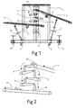
- the apparatus comprises a supporting frame 1 which may be conveniently mounted on castors 2 permitting the apparatus to be moved to become part of any production line, where feet 2a can be screwed down to support the frame and prevent unwanted movement.
- An input conveyor 3 carries the meat products into the apparatus, for example from a spreading chute (not shown).
- the input conveyor 3 comprises a wire mesh belt driven by an electric motor 4, the whole conveyor being hingedly mounted on the upper part of the supporting frame 1 and supported at its other end by a screw jack 5 mounted on the lower part of the frame 1, the jack 5 serving to control the receiving position of the lower part of the conveyor.
- Each conveyor comprises a wire mesh belt, and the uppermost conveyor 6 is arranged with its conveying direction opposite to that of the input conveyor 3, while each successive intermediate conveyor 7 and 8 below it operates to convey in the opposite direction from the preceding conveyor above it.
- An output conveyor 9 is mounted on the frame 1 vertically below the final intermediate conveyor 8 and again runs in the opposite direction to the conveyor 8, so as to convey the aligned products out of the apparatus and on to the next processing stage.
- the output conveyor 9 is mounted in a similar manner to the input conveyor 3, being pivotally mounted on the frame 1 at one end thereof and carried by a screw jack 10 towards the other end thereof so as to permit adjustment of the discharge position of the output conveyor.
- the output conveyor 9 is also provided with its own drive motor 11, running independently of the speed of the apparatus.
- Each of the intermediate conveyors 6, 7 and 8 is arranged with its conveying direction at an acute angle, for example 5° to 10°, to the horizontal such that the products falling onto it from the preceding conveyor are conveyed generally upwardly before dropping off the end of the conveyor and onto the next conveyor below.
- the intermediate conveyors are mounted in the frame 1 in such a manner as to be vertically adjustable in position, whereby the vertical spacing between the conveyors may be set according to the products being aligned, and the angle of the conveyor to the horizontal may also be varied. This may be achieved by using a lockable pivot mounted in a vertical slot 12.
- the angles may be adjusted by means of servo motors between the frame 1 and the intermediate conveyors, permitting adjustment to accommodate different products to be carried out semi-automatically in accordance with predetermined settings.
- the intermediate conveyors 6, 7 and 8 may be individually driven by a respective electric motor, but are suitably powered by a common drive motor 13 through an endless drive chain (not shown).
- Each successive conveyor in the downward path of the products is driven with a linear speed slightly greater than the preceding conveyor.
- the combination of the reverse in direction as the product falls from one conveyor to the next, coupled with the slight increase in speed serves to call the products progressively into an orientation where the lengthwise axis of the product is substantially parallel to the longitudinal axis of the conveyors.
- the vertical spacing between the conveyors is suitably selected so that one end of the product reaches the next conveyor below as the other end leaves contact with the first conveyor.
- the belt speeds will be of the order of 10 to 12 metres per minute.
- the differential speeds may be achieved by the use of different-sized sprockets for the different conveyors. The difference of 1 to 2 teeth from one sprocket to another will generally be sufficient to provide the desired acceleration of the product as it dropped onto the conveyor to assist alignment of the product.
- a food processing line may therefore include more than one apparatus in accordance with the invention for aligning the products prior to different stages.
- the tested apparatus included five conveyors.
- the speed referred to in Figure 3 is the speed of the discharge conveyor belt. In all tests the discharge conveyor speed was about 50% higher than the speed of the first conveyor belt. Increases in speed of subsequent conveyor belts were uniform. All of the conveyors were positioned horizontally. The conveyor belts were positioned equidistant from each other. The "height relative to product" shown in Figure 3 refers to the distance between subsequent conveyor belts being either 2/3, 1/2 or 1/3 of the average unravelled product length. The pieces of flexible material each had a weight in the range of from 25 to 35 grams.
- the pieces of flexible material were 110 mm long.
Landscapes
- Engineering & Computer Science (AREA)
- Life Sciences & Earth Sciences (AREA)
- Wood Science & Technology (AREA)
- Zoology (AREA)
- Food Science & Technology (AREA)
- Mechanical Engineering (AREA)
- Attitude Control For Articles On Conveyors (AREA)
- Structure Of Belt Conveyors (AREA)
Applications Claiming Priority (2)
| Application Number | Priority Date | Filing Date | Title |
|---|---|---|---|
| GB0312588 | 2003-06-02 | ||
| GB0312588A GB0312588D0 (en) | 2003-06-02 | 2003-06-02 | Aligning device |
Publications (1)
| Publication Number | Publication Date |
|---|---|
| EP1483970A1 true EP1483970A1 (fr) | 2004-12-08 |
Family
ID=9959152
Family Applications (1)
| Application Number | Title | Priority Date | Filing Date |
|---|---|---|---|
| EP04253259A Withdrawn EP1483970A1 (fr) | 2003-06-02 | 2004-06-02 | Dispositif d'alignement de produits de viande |
Country Status (2)
| Country | Link |
|---|---|
| EP (1) | EP1483970A1 (fr) |
| GB (1) | GB0312588D0 (fr) |
Cited By (2)
| Publication number | Priority date | Publication date | Assignee | Title |
|---|---|---|---|---|
| WO2010046366A1 (fr) * | 2008-10-20 | 2010-04-29 | Ihf Food | Procédé et système pour traiter des parties d'animaux abattus |
| US9834384B2 (en) | 2016-01-23 | 2017-12-05 | John Bean Technologies Corporation | Gap adjustment assembly for blade portioner conveyors |
Citations (3)
| Publication number | Priority date | Publication date | Assignee | Title |
|---|---|---|---|---|
| DE1454072A1 (de) * | 1962-07-12 | 1969-10-16 | Nordischer Maschb Rudolf Baade | Verfahren und Vorrichtung zum Wenden von Fischfilets fuer die lagegerechte Zufuehrung zur Enthaeutemaschine |
| US4958409A (en) * | 1988-11-10 | 1990-09-25 | Nordischer Maschinenbau Rud. Baader Gmbh & Co. | Method and apparatus for turning over and stretching fish fillets |
| WO1998046086A1 (fr) * | 1997-04-16 | 1998-10-22 | Marel Hf. | Appareil et procede d'alimentation et de transport automatiques et commandes de filets de poisson ou de morceaux de viande dans un systeme de traitement par lignes de production |
-
2003
- 2003-06-02 GB GB0312588A patent/GB0312588D0/en not_active Ceased
-
2004
- 2004-06-02 EP EP04253259A patent/EP1483970A1/fr not_active Withdrawn
Patent Citations (3)
| Publication number | Priority date | Publication date | Assignee | Title |
|---|---|---|---|---|
| DE1454072A1 (de) * | 1962-07-12 | 1969-10-16 | Nordischer Maschb Rudolf Baade | Verfahren und Vorrichtung zum Wenden von Fischfilets fuer die lagegerechte Zufuehrung zur Enthaeutemaschine |
| US4958409A (en) * | 1988-11-10 | 1990-09-25 | Nordischer Maschinenbau Rud. Baader Gmbh & Co. | Method and apparatus for turning over and stretching fish fillets |
| WO1998046086A1 (fr) * | 1997-04-16 | 1998-10-22 | Marel Hf. | Appareil et procede d'alimentation et de transport automatiques et commandes de filets de poisson ou de morceaux de viande dans un systeme de traitement par lignes de production |
Cited By (2)
| Publication number | Priority date | Publication date | Assignee | Title |
|---|---|---|---|---|
| WO2010046366A1 (fr) * | 2008-10-20 | 2010-04-29 | Ihf Food | Procédé et système pour traiter des parties d'animaux abattus |
| US9834384B2 (en) | 2016-01-23 | 2017-12-05 | John Bean Technologies Corporation | Gap adjustment assembly for blade portioner conveyors |
Also Published As
| Publication number | Publication date |
|---|---|
| GB0312588D0 (en) | 2003-07-09 |
Similar Documents
| Publication | Publication Date | Title |
|---|---|---|
| US8359995B2 (en) | Hybrid apparatus for applying coating to products and methods of use thereof | |
| US20120244264A1 (en) | Apparatus for applying coating to products and methods of use thereof | |
| EP0411174B1 (fr) | Dispositif de distribution pour l'enrobage de produits alimentaires | |
| US11582975B2 (en) | Food processing system and a food processing method | |
| US5924356A (en) | Food product breading machine | |
| US6748837B2 (en) | Apparatus for sizing and halving food product | |
| AU2005217998B2 (en) | Forming and Cooking with Controlled Curtain Spillage | |
| US7434677B2 (en) | Apparatus for aligning meat products | |
| JP2001516597A (ja) | パン生地の小片を処理する装置および方法 | |
| US7770717B2 (en) | Device for transfer of items | |
| US5641055A (en) | Conveyor belt | |
| EP1483970A1 (fr) | Dispositif d'alignement de produits de viande | |
| EP3148903B1 (fr) | Système de distribution destiné à acheminer des produits de forme irrégulière tels que des poires jusqu'à un moyen de séparation, et système et procédé de transport associés | |
| US20090090255A1 (en) | Agricultural product peeling apparatus | |
| JPH0551124A (ja) | 選別装置の供給装置 | |
| US3757945A (en) | Apparatus and method for separating hearts and livers from a mixture thereof | |
| JP2008285328A5 (fr) | ||
| US11142409B1 (en) | Conveyor system with orientation of conveyed food products | |
| IL33956A (en) | Fruit sizing apparatus | |
| DK200400106Y6 (da) | Apparat til sortering af skaldyr | |
| CN110122541A (zh) | 一种对虾分离排序装置 | |
| JPH0532313A (ja) | 選別装置の供給装置 | |
| CA2697897A1 (fr) | Installation hybride d'application d'enduit a des articles, et methodes d'utilisation connexes | |
| US3391769A (en) | Feeding of fruit and vegetable articles | |
| US1509216A (en) | Fruit-grading machine |
Legal Events
| Date | Code | Title | Description |
|---|---|---|---|
| PUAI | Public reference made under article 153(3) epc to a published international application that has entered the european phase |
Free format text: ORIGINAL CODE: 0009012 |
|
| AK | Designated contracting states |
Kind code of ref document: A1 Designated state(s): AT BE BG CH CY CZ DE DK EE ES FI FR GB GR HU IE IT LI LU MC NL PL PT RO SE SI SK TR |
|
| AX | Request for extension of the european patent |
Extension state: AL HR LT LV MK |
|
| AKX | Designation fees paid | ||
| REG | Reference to a national code |
Ref country code: DE Ref legal event code: 8566 |
|
| STAA | Information on the status of an ep patent application or granted ep patent |
Free format text: STATUS: THE APPLICATION IS DEEMED TO BE WITHDRAWN |
|
| 18D | Application deemed to be withdrawn |
Effective date: 20050609 |