EP1483992B1 - Automatische kaffeezubereitungsvorrichtung - Google Patents
Automatische kaffeezubereitungsvorrichtung Download PDFInfo
- Publication number
- EP1483992B1 EP1483992B1 EP02708378A EP02708378A EP1483992B1 EP 1483992 B1 EP1483992 B1 EP 1483992B1 EP 02708378 A EP02708378 A EP 02708378A EP 02708378 A EP02708378 A EP 02708378A EP 1483992 B1 EP1483992 B1 EP 1483992B1
- Authority
- EP
- European Patent Office
- Prior art keywords
- carriage
- spindle
- piston
- cavity
- nut
- Prior art date
- Legal status (The legal status is an assumption and is not a legal conclusion. Google has not performed a legal analysis and makes no representation as to the accuracy of the status listed.)
- Expired - Lifetime
Links
- 230000000903 blocking effect Effects 0.000 claims description 8
- 238000001802 infusion Methods 0.000 claims description 6
- XLYOFNOQVPJJNP-UHFFFAOYSA-N water Substances O XLYOFNOQVPJJNP-UHFFFAOYSA-N 0.000 claims description 4
- 230000002093 peripheral effect Effects 0.000 claims description 3
- 238000000926 separation method Methods 0.000 claims description 3
- 230000006835 compression Effects 0.000 description 3
- 238000007906 compression Methods 0.000 description 3
- 239000000843 powder Substances 0.000 description 3
- 238000004140 cleaning Methods 0.000 description 2
- 230000007257 malfunction Effects 0.000 description 2
- 230000000284 resting effect Effects 0.000 description 2
- 230000000717 retained effect Effects 0.000 description 2
- 238000010793 Steam injection (oil industry) Methods 0.000 description 1
- 238000010276 construction Methods 0.000 description 1
- 238000006073 displacement reaction Methods 0.000 description 1
- 238000000605 extraction Methods 0.000 description 1
- 238000010438 heat treatment Methods 0.000 description 1
- 238000000034 method Methods 0.000 description 1
Images


Classifications
-
- A—HUMAN NECESSITIES
- A47—FURNITURE; DOMESTIC ARTICLES OR APPLIANCES; COFFEE MILLS; SPICE MILLS; SUCTION CLEANERS IN GENERAL
- A47J—KITCHEN EQUIPMENT; COFFEE MILLS; SPICE MILLS; APPARATUS FOR MAKING BEVERAGES
- A47J31/00—Apparatus for making beverages
- A47J31/24—Coffee-making apparatus in which hot water is passed through the filter under pressure, i.e. in which the coffee grounds are extracted under pressure
- A47J31/34—Coffee-making apparatus in which hot water is passed through the filter under pressure, i.e. in which the coffee grounds are extracted under pressure with hot water under liquid pressure
- A47J31/36—Coffee-making apparatus in which hot water is passed through the filter under pressure, i.e. in which the coffee grounds are extracted under pressure with hot water under liquid pressure with mechanical pressure-producing means
- A47J31/3604—Coffee-making apparatus in which hot water is passed through the filter under pressure, i.e. in which the coffee grounds are extracted under pressure with hot water under liquid pressure with mechanical pressure-producing means with a mechanism arranged to move the brewing chamber between loading, infusing and ejecting stations
- A47J31/3609—Loose coffee being employed
- A47J31/3619—Means to remove coffee after brewing
-
- A—HUMAN NECESSITIES
- A47—FURNITURE; DOMESTIC ARTICLES OR APPLIANCES; COFFEE MILLS; SPICE MILLS; SUCTION CLEANERS IN GENERAL
- A47J—KITCHEN EQUIPMENT; COFFEE MILLS; SPICE MILLS; APPARATUS FOR MAKING BEVERAGES
- A47J31/00—Apparatus for making beverages
- A47J31/24—Coffee-making apparatus in which hot water is passed through the filter under pressure, i.e. in which the coffee grounds are extracted under pressure
- A47J31/34—Coffee-making apparatus in which hot water is passed through the filter under pressure, i.e. in which the coffee grounds are extracted under pressure with hot water under liquid pressure
- A47J31/36—Coffee-making apparatus in which hot water is passed through the filter under pressure, i.e. in which the coffee grounds are extracted under pressure with hot water under liquid pressure with mechanical pressure-producing means
- A47J31/3604—Coffee-making apparatus in which hot water is passed through the filter under pressure, i.e. in which the coffee grounds are extracted under pressure with hot water under liquid pressure with mechanical pressure-producing means with a mechanism arranged to move the brewing chamber between loading, infusing and ejecting stations
- A47J31/3609—Loose coffee being employed
- A47J31/3614—Means to perform transfer from a loading position to an infusing position
Definitions
- the present invention relates to an automated device for brewing express coffee, intended for its use in coffee makers being provided with a brewing chamber to which the ground coffee is carried and to which hot pressurised water is supplied, which then passes through the ground coffee to obtain the infusion.
- the device of the invention is of the type having a structure which comprises a rotating spindle that cannot move in an axial sense and is provided with a nut connected to a moving carriage, which carriage is provided with a through cavity parallel to the spindle that can be closed on the top and bottom by pistons to define a brewing chamber.
- Swiss patent 641030 (EP 0061472) describes a coffee maker with a brewing device of the above-described type, in which the pistons that can close the brewing chamber are driven hydraulically, which makes the system complex and considerably increases the cost of the coffee maker.
- EP 0528757 describes a brewing device for a coffee maker which comprises a brewing cylinder with a perforation that can be closed by two pistons in order to define the brewing chamber, with one of these pistons fixed and placed opposite the perforation and with the cylinder and the other piston free to move axially.
- the cylinder engages a parallel spindle, so that when the latter rotates in one sense or another the cylinder will move in the desired sense.
- Document US-5471910 discloses the preamble of claim 1.
- the fixed cylinder prevents the axial loading of coffee powder, so that a retractable, inclined pivoting funnel must be provided to load the coffee.
- the movable piston is mounted on a tubular projection attached to the frame of the machine, with interposed gaskets which must provide a greater friction than the friction between said piston and the perforation of the brewing cylinder. This arrangement complicates the assembly and operation of the system, and can furthermore result in operational problems and cause frequent malfunctions.
- the object of the present invention is to eliminate the above-described problems by means of an automated brewing device which allows the direct axial loading of coffee powder to the brewing chamber without requiring funnels or lateral loading ramps.
- a further object of the invention is to simplify the operational system of the moving plunger or piston, so that when it is locked in place or free to move its position is secured at all times by sturdy elements which cannot malfunction.
- an object of the invention is to simplify the tasks of assembling and disassembling the automated brewing device in the coffee maker, while also allowing it to be mounted in several arrangements which optimise its position according to the desired configuration of the coffee maker.
- the brewing device of the invention is of the type described initially and comprises a structure in which a revolving spindle is mounted without freedom to move axially.
- This spindle is provided with a nut that is laterally connected to a carriage, which carriage is driven along by the nut during the axial motion of said nut.
- This carriage has a through cavity parallel to a spindle, the cavity being closed on the bottom by a lower piston that can move partially within said cavity, and is closed on the top by an independent upper piston, so that the brewing chamber is thereby determined between the two pistons.
- the upper piston is mounted on a support that can turn about the spindle between an operative position, in which the piston is opposite the carriage cavity, and an inactive position in which said piston is out of the projection of the cavity.
- This support also holds a tube for loading the ground coffee, which can turn together with the support between a loading position, in which it is aligned with the chamber and its top mouth, and an inactive position in which it is no longer in this alignment. In the first position of the loading tube the upper piston is in its inactive position, while in the second position of the loading tube the piston is in its operative position.
- both the upper piston and the lower piston are provided with ducts for water inlet and infusion outlet, such that this operation can be performed both upwards and downwards.
- the brewing chamber and the entire brewing circuit can be heated so that the coffee infusion may be obtained at any time at the desired temperature, with this temperature kept constant for each infusion. Heating can be obtained by steam injection, by an electrical resistance or by any other heat source.
- the bottom piston extends downwards as a tubular shaft that ends with a bottom widening provided with a peripheral groove, to which may be coupled an elastic blocking element which acts when the nut and the carriage reach their lowermost position.
- This bottom widening of the shaft acts on the blocking element and causes it to deform elastically, so that it is inserted in the groove or released from it as the widening is pushed downwards by the carriage or as the piston is pushed upwards by the same carriage, always with a force greater than the frictional force between the piston and the carriage cavity.
- the structure of the brewing device of the invention is provided with an opening placed opposite said cavity, through which the coffee powder is poured when the loading tube is situated opposite said cavity.
- the upper support that bears the upper piston and the loading tube is part of a C-shaped part which has a central segment that runs parallel to the spindle on the opposite side to the carriage, as well as side segments that are perpendicular to the spindle axis and which can turn freely about said spindle, with the upper segment having an overhanging projection from which the upper piston and the loading tube are suspended.
- the nut that provides the motion of the carriage comprises two parallel threaded rings joined by an external axial rib by which the nut is connected to a cam.
- This cam controls their motion by causing a rotation or an axial displacement when it reaches certain positions.
- the cam consists of an approximately semi-cylindrical wall mounted around the spindle on the side opposite the carriage and co-axial to said spindle, with the central segment of the above-mentioned C-part running outside this wall.
- the wall that determines this cam is provided with two axial grooves on the surface facing the spindle, placed at different heights, out of alignment and having equal widths.
- the upper groove and the bottom groove are separated by an intermediate window with a height approximately equal to that of the rib that joins the two rings of the nut.
- This window is limited on its top and bottom by parallel helical ramps, with the upper groove ending at the window at the highest point of the upper helical ramp and the bottom groove ending at the lowest point of the bottom ramp.
- the angular separation between the two axial grooves is the same as the angle turned by the upper support between the coffee-loading and brewing positions.
- the central segment of the C-shaped support is provided with an intermediate axial groove having a width equal to that of the grooves of the semi-cylindrical wall and a lower height than the window of said wall.
- This groove enters in the window to receive the rib that joins the nut rings as when said rib is opposite the top or bottom groove of the semi-cylindrical wall, thereby allowing the nut to turn while also making it move in an axial sense as defined by the helical ramps which limit the window on the top and bottom.
- the height of the upper groove of the semi-cylindrical wall will correspond to the axial run of the nut when the carriage moves between its top limiting position and the coffee-loading position or vice versa, while the height of the lower groove corresponds to the axial run of the nut between the bottom limiting position of the carriage and the coffee-loading position or vice versa.
- the elastic blocking element in the widening of the lower piston shaft can consist of two rods secant to an opening located at the bottom part of the structure, in a position opposite the shaft of the lower piston.
- This opening has a width that is larger than the bottom widening of the shaft, and it is placed at the height reached by the widening when the spindle nut and the carriage reach their lowermost position.
- These rods define an opening with a width that is slightly smaller than the widening of the shaft, and they are elastically deformed as they are pushed by said widening until they reach its same width.
- the carriage that defines the brewing chamber is provided on its upper base with a guillotine connected to a drive mechanism that causes it to move transversally on said base between a retracted position, in which it is behind the outlet mouth of the carriage cavity, and an anterior position in which it is in front of said opening. As it moves from the retracted position to the anterior position it pushes the hammer, which has been previously ejected from the brewing chamber.
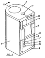
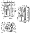
- the automated device for brewing coffee of the invention comprises a structure that, in the example shown in figure 1, consists of an upper plate 1, a lower plate 2 and side walls 3. Mounted inside this structure, and as seen best in figure 2, is a revolving spindle 4 that cannot move axially and which bears a nut 5, shown in perspective in figure 15.
- This nut comprises two threaded rings joined by an axial rib 6; attached to the side of this nut is a carriage 7, provided with a rear ring 8 through which can pass freely the spindle 4, and which is meant to be inserted between the rings of the nut 5, as can be seen in figures 2, 15 and 16.
- the carriage 7 is also provided with a cavity 9 parallel to the spindle 4 and which is open on the top.
- This cavity houses a piston 10 that may move longitudinally inside said cavity, and which extends on the bottom as a shaft 11 which projects out through the orifice 12 on the bottom of the cavity 9.
- a widening 13 At the end of the shaft 11 is a widening 13 with a peripheral groove 14 and which at its free end has a conical segment 15.
- a support 16 that is part of a C-shaped part 17, the lateral segments of the latter being provided with openings 18 through which pass the end segments of the spindle 4, which are not threaded, so that the part 17 can turn freely about said spindle.
- Its upper end forms an overhanging projection in the form of a support 16, which bears an upper piston 20 and a loading tube 21, figures 2 to 5.
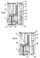
- the C-shaped part 17 and therefore the support 16 can revolve between two extreme positions: one for loading coffee, as shown in figure 12, in which the coffee-loading tube 21 is placed opposite the cavity 9 of the carriage 7, while the upper piston 20 is placed out of the projection of said cavity; and a brewing position as shown in figure 11, in which the upper piston 20 is opposite the cavity 9 of the carriage 7 and the loading tube 21 is left out of the projection of said cavity.
- the bottom plate 2 of the structure is provided with an opening 22 with a slightly larger perimeter than the widening 13 of the shaft 11. This opening is crossed by two rods 23 which occupy diametrically opposite positions and are separated from each other by a distance that is less than the width of the groove 14 of the shaft 16. These rods are elastically deformable, so that they can act as a blocking element when receiving the groove 14 of the aforementioned widening.
- Both the bottom piston 10 and the upper piston 20 are provided with ducts 25 and 26 allowing water to enter and the infusion to leave in any sense.
- the top plate in a position opposite the cavity 9 the top plate is provided with an opening 27 so that the loading tube 21 will be opposite this opening when it reaches the coffee-loading position.
- the carriage 7 is guided in its vertical motion by the columns 28.
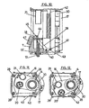
- Said cam consists of two axial grooves 31 and 32, located on the surface opposite the spindle, at different heights and not aligned with each other, with the two grooves having the same width that is slightly greater than that of the rib 6 of the nut 5. These two grooves are separated by an intermediate window 33, the height of which is approximately the same as that of the rib 6.
- This opening is limited on the top and bottom by parallel helical ramps 34 and 35, with the upper groove 31 ending at the window 33 at the highest point of the upper helical ramp 34, while the bottom groove 32 ends at the window 33 at the lowest point of the bottom ramp 35.
- the angular separation between the two grooves 31 and 32 is approximately the same as the turning angle of the upper support 16, and therefore of the C-shaped part 17, between the coffee-loading and brewing positions.
- the central segment of the C-shaped part 17 is provided with an intermediate axial groove 36 which has a width equal to that of the grooves 31 and 32 of the wall 30 and a lower height than the window 33 of said wall.
- This groove 36 enters through the window 33 to receive the rib 6 of the nut 5, when said rib is opposite the upper or lower groove of the wall 30, thereby allowing the nut to turn while also making it move in an axial sense as defined by the inclination of the helical ramps 34 and 35 which limit the window 33 on the top and bottom.
- the carriage is provided on its top base with a guillotine 38 that is related to a drive mechanism that causes it to move transversally on said base between a retracted position, figure 8, in which it is behind the outlet mouth of the cavity 9, and a forward position, figure 10, in which it is in front of said opening.
- Said drive mechanism for the guillotine 38 consists of an elbowed lever 39 placed on a side of the carriage and hinged to it at its elbow by a shaft 40.
- the segment of the lever that remains under this hinged shaft 40 is provided with a lateral stop 41 that, during the vertical motion of the carriage 7, rests on the edge 42 of the part 30 and that when the carriage reaches the bottom widening 13 of shaft 11, figure 9, meets a stop 43 formed by the aforementioned edge and thus making the lever 39 swivel until it reaches the position of figure 10.
- the lever 39 is provided with an arched slot 44 through which it is hinged by means of a pivot 45 to the guillotine 38, so that it moves along the base of the carriage 7.
- the device of the invention works as follows:
- Figure 3 shows the device in a resting position, in which the groove 36 of the C-part 17 is inside the window 33, as shown in figure 17, with the rib 6 of the nut 5 housed partially in said groove 36 and partially in the upper groove 31 of the cam.
- the spindle 4 is turned, making the carriage 7 descend together with the nut 5 until the rib 6 is placed in the window 33, as shown in figure 19, at which moment the groove 36 together with the C-part 17 move along the window 33 to the position 36', in which the loading tube 21 is left opposite the chamber 9, at which time the coffee is loaded.
- the spindle then turns in the opposite sense and again moves the groove of the C-part from the position 36' to the position 36 of figure 21, so that the rib 6 is left opposite the upper groove 31, and then moves along it until it reaches its extreme upper position in which the coffee is compressed and brewing begins, as shown in figure 6.
- the rib 6 reaches the extreme upper position as shown in figure 18.
- the position of the cavity or brewing chamber 9 is related to the position of the upper piston 20 and the loading tube 21.
Landscapes
- Engineering & Computer Science (AREA)
- Mechanical Engineering (AREA)
- Food Science & Technology (AREA)
- Apparatus For Making Beverages (AREA)
- Tea And Coffee (AREA)
Claims (9)
- Automatische Kaffeezubereitungsvorrichtung für Express-Kaffee, enthaltend eine Struktur, in welcher eine drehbare Spindel (4) derart angeordnet ist, dass diese axial nicht bewegbar ist und eine Nuss(5) trägt, welche seitlich mit einem Wagen (7) verbunden ist, welcher mit der genannten Nuss (5) bewegbar ist, wobei der Wagen (7) eine Durchgangsausnehmung (9) enthält, welche parallel zur Spindel (4) ist und am Boden durch einen unteren Kolben (10) geschlossen ist, welcher entlang eines Teils dieser Ausnehmung (9) bewegbar ist, während das obere Ende der Ausnehmung (9) durch einen oberen, axial nicht bewegbaren Kolben (20) abgeschlossen ist, wodurch die Zubereitungskammer definiert ist, wobei jene einen über der Spindel (4) angeordneten oberen Träger (16) mit einer Verlängerung enthält, welche den Wagen (7) in Form eines flachen Segments übergreift, welches den oberen Kolben (20) und ein Füllrohr 21 trägt, wobei der genannte Träger (16) um die Spindel zwischen zwei Extrem-Positionen um die Spindel frei gedreht werden kann und zwar in eine Einfüllposition des Kaffees, in welcher das Füllrohr (21) gegenüber der Ausnehmung (9) des Wagens (7) platziert ist und der obere Kolben (20) außerhalb der Projektion der genannten Ausnehmung (9) platziert ist, und ferner in einer Zubereitungsposition, In welcher der Kolben (20) gegenüber der Ausnehmung (9) des Wagens platziert ist und das Füllrohr (21) außerhalb der Projektion der genannten Ausnehmung (9) platziert ist,
dadurch gekennzeichnet, dass der untere Kolben (10) sich abwärts als ein rohrförmiger Schaft (11) erstreckt, welcher in einer Bodenerweiterung (13) endet, welche mit einer Umfangsnut (14) versehen ist, in welche ein elastisches Blockierelement (23) koppelbar ist, wenn die Nuss (5) und der Wagen (7) ihre unterste Position erreichen;
wobei die Bodenerweiterung (13) des Schafts (11) elastisch auf das Blockierelement (23) einwirkt, um dieses derart zu deformieren, dass die Erweiterung (13) des Schaftes (11) in die genannte Nut (14) gekoppelt oder von dieser freigegeben ist, sobald der Wagen (7) die Erweiterung nach unten stößt oder den Kolben nach oben stößt,
wobei in jedem Fall eine Kraft erzeugt wird, welche größer ist als die Reibung zwischen dem Kolben (10) und der Ausnehmung (9) des Wagens (7), wobei die beiden Kolben (10, 20) mit korrespondierenden Zuführungen (25, 26) für den Wassereinlaß und den Aufgußauslaß versehen sind, und wobei die Struktur oberhalb des Wagens (7) mit einer Öffnung gegenüber der Ausnehmung (9) des Wagens versehen ist und ferner das Füllrohr (21) gegenüber der genannten Ausnehmung (9) platziert ist, sobald diese die Kaffee-Einfüllposition erreicht hat. - Vorrichtung nach Anspruch 1, dadurch gekennzeichnet, dass der genannte obere Träger (16) Teil eines C-förmigen Teiles (17) ist, welcher ein zentrales, parallel zur Spindel (4) laufendes Segment und Seitensegmente aufweist, welche senkrecht zur Achse der Spindel (4) und um diese frei drehbar sind, wobei das obere Segment die überhängende Verlängerung des oberen Trägers (16) bildet, welcher den oberen Kolben und das Einfüllrohr (20) trägt.
- Vorrichtung nach Anspruch 1, dadurch gekennzeichnet dass die genannte Nuss(5) aus zwei parallelen Ringen gebildet ist, welche mittels einer äußeren axialen Rippe (6) verbunden sind.
- Vorrichtung nach Anspruch 1, dadurch gekennzeichnet, dass das elastische Blockierelement (23) aus zwei Stäben gebildet ist, welches durch eine Öffnung (22) des Bodenteils (2) der Struktur durchgreift in einer Position gegenüber dem Bodenkolben (10), welches eine Weite etwas größer als untere Erweiterung des Schaftes (11) aufweist und welches in einer Höhe angeordnet ist, welche von der Erweiterung (12) erreicht wird, wenn die Spindelnuss (5) und der Wagen ihre unterste Position erreichen,
wobei diese Stäbe (23) eine Öffnungsweite definieren, welche geringfügig kleiner ist als die Erweiterung (12) für den Schaft und welche elastisch durch die genannte Erweiterung deformiert werden bis sie in der Weite angepasst sind. - Vorrichtung nach Anspruch 1, dadurch gekennzeichnet, dass der vorgenannte Wagen (7) an seiner oberen Basis mit einer Guillotine (38) versehen ist, zugeordnet zu einem Antriebsmechanismus, mit welchem die Guillotine (38) transversal entlang der genannten Basis bewegbar ist, zwischen einer zurückgezogenen Position, in welche jene hinter einer Auslassmündung der Wagenöffnung (9) angeordnet ist und eine vordere Position, in welcher jene sich in Front der genannten Mündung befindet.
- Vorrichtung nach Anspruch 5, dadurch gekennzeichnet, dass der Antriebsmechanismus der Guillotine (38) einen abgewinkelten, an einer Seite des Wagens (7) angeordneten Hebel aufweist und an jenem an dessen Winkelteil angelenkt ist, und dass jene an dem Segment vorgesehen ist, welches sich unterhalb des Gelenks mit einer lateralen Projektion befindet, welche einen Stopp (43) der Struktur erreicht, wenn der Wagen (7) die Bodenerweiterung (13) des Kolbenschaftes (11) erreicht, wobei der Hebel (39) gedreht wird, während an seinem oberen Ende der Hebel (39) mit der Guillotine (38) durch einen gebogenen Schlitz (34) in Berührung gelangt, wodurch der letztere linear entlang der oberen Basis des Wagens (7) zwischen seiner zurückgezogenen und seiner vorderen Positionen bewegt wird oder umgekehrt.
- Vorrichtung nach Anspruch 5 und 6, dadurch gekennzeichnet, dass die Guillotine (38) mit dem Wagen (7) mittels Führungen verbunden ist, welche parallel zur oberen Basis des genannten Wagens (7) verlaufen.
- Vorrichtung nach Anspruch 1 oder 2, dadurch gekennzeichnet, dass die Nuss (5) auf der Spindel (14) mit einem Mitnehmer verbunden ist, welcher deren Bewegung derart steuert, dass jene dreht oder sich in einer geraden Linie bewegt, wenn sie bestimmte Positionen erreicht ist.
- Vorrichtung nach den Ansprüchen 1 und 8, dadurch gekennzeichnet, dass der genannte Mitnehmer eine näherungsweise halbzylindrische Wand (30) enthält, welche um die Spindel (4) auf der zum Wagen (7) gegenüberliegenden Seite und koaxial mit der genannten Spindel (4) angeordnet ist, mit einem zentralen Segment eines C-förmigen Teils (17) laufend außerhalb von und nahe zu der genannten Wand (8); diese Wand ist an der Oberfläche, welche benachbart der Spindel (4) angeordnet ist, mit zwei in unterschiedlichen Höhen angeordneten axialen Nuten versehen, welche nicht miteinander ausgerichtet und übereinstimmende Weiten aufweisen, wobei die obere Nut (31) und die untere Nut (32) durch ein dazwischen liegendes Fenster (33) getrennt sind mit einer Höhe näherungsweise gleich zu derjenigen der Rippe (6), welche in Eingriff steht mit den beiden Ringen der Nuss(5), und wobei dieses Fenster (33) an seiner Spitze und seinem Boden durch parallele schraubenförmige Rampen (34, 35) begrenzt ist, wobei die obere Nut (31) am Fenster an dem obersten Punkt der oberen schraubenförmigen Rampe (34) endet und die untere Nut (32) an dem tiefsten Punkt der unteren Rampe (35) endet und wobei der Winkelabstand zwischen den beiden axialen Nuten der gleiche ist wie der Winkel, um welchen der obere Träger (16) zwischen der Kaffee-Einfüll- und der Brühposition drehbar ist, und wobei das zentrale Segment des C-förmigen Trägers (17) mit einer dazwischen angeordneten axialen Nut (36) versehen ist, welche eine Weite gleich derjenigen der genannten Nuten (31, 32) der halbzylindrischen Wand (30) und eine geringere Höhe als das Fenster (33) der genannten Wand (30) aufweist, wobei ferner die Nut (36) durch das Fenster (33) durchgeführt ist, um die Rippe (6), welche mit den Ringen der Nuss in Eingriff steht, wenn die genannte Rippe (6) sich gegenüber der oberen oder der unteren Nut der halbzylindrischen Wand (30) befindet, wodurch der Nuss (5) die Drehung ermöglicht wird, während sie sich auch in axialer Richtung, wie vorgegeben durch die schraubenförmigen Rampen (34, 35) bewegt, welche das vorgenannte Fenster (33) an der Spitze und am Boden begrenzen.
Applications Claiming Priority (1)
| Application Number | Priority Date | Filing Date | Title |
|---|---|---|---|
| PCT/ES2002/000105 WO2003075725A1 (es) | 2002-03-08 | 2002-03-08 | Mecanismo automatico de erogacion de café |
Publications (2)
| Publication Number | Publication Date |
|---|---|
| EP1483992A1 EP1483992A1 (de) | 2004-12-08 |
| EP1483992B1 true EP1483992B1 (de) | 2005-07-27 |
Family
ID=27799016
Family Applications (1)
| Application Number | Title | Priority Date | Filing Date |
|---|---|---|---|
| EP02708378A Expired - Lifetime EP1483992B1 (de) | 2002-03-08 | 2002-03-08 | Automatische kaffeezubereitungsvorrichtung |
Country Status (6)
| Country | Link |
|---|---|
| EP (1) | EP1483992B1 (de) |
| AT (1) | ATE300221T1 (de) |
| AU (1) | AU2002242747A1 (de) |
| DE (1) | DE60205282T2 (de) |
| ES (1) | ES2245399T3 (de) |
| WO (1) | WO2003075725A1 (de) |
Families Citing this family (4)
| Publication number | Priority date | Publication date | Assignee | Title |
|---|---|---|---|---|
| DK2042062T3 (da) * | 2007-09-25 | 2010-08-02 | Schaerer Ag | Brygindretning til en kaffemaskine |
| EP2196115A1 (de) | 2008-12-12 | 2010-06-16 | Jura Elektroapparate AG | Antrieb für eine Kaffeebrühvorrichtung und Kaffeebrühvorrichtung |
| DE202009000075U1 (de) * | 2009-02-02 | 2010-06-24 | Wik Far East Ltd. | Brüheinheit |
| NL2006503C2 (nl) * | 2011-03-31 | 2012-10-02 | Bravilor Holding Bv | Drankbereidingsinrichting. |
Family Cites Families (5)
| Publication number | Priority date | Publication date | Assignee | Title |
|---|---|---|---|---|
| IT1222609B (it) * | 1987-09-07 | 1990-09-05 | Vincenzo Cinoni | Gruppo automatico di ingusione per macchine per la preparazione di caffe' espresso |
| US5316781A (en) * | 1991-07-30 | 1994-05-31 | Sintra Holding Ag | Brewing device for a coffee machine and method of producing coffee |
| DE4329597C1 (de) * | 1993-09-02 | 1994-12-15 | Hgz Maschinenbau Ag | Kaffeemaschinenautomat |
| IT1262342B (it) * | 1993-12-20 | 1996-06-19 | G3 Ferrari Srl | Macchina automatica per fare caffe' espresso o bevande analoghe. |
| DE19841880B4 (de) * | 1998-09-11 | 2009-02-05 | Niro-Plan Ag | Brüheinheit für Kaffeemaschinenautomaten |
-
2002
- 2002-03-08 ES ES02708378T patent/ES2245399T3/es not_active Expired - Lifetime
- 2002-03-08 AU AU2002242747A patent/AU2002242747A1/en not_active Abandoned
- 2002-03-08 WO PCT/ES2002/000105 patent/WO2003075725A1/es not_active Ceased
- 2002-03-08 AT AT02708378T patent/ATE300221T1/de not_active IP Right Cessation
- 2002-03-08 DE DE60205282T patent/DE60205282T2/de not_active Expired - Lifetime
- 2002-03-08 EP EP02708378A patent/EP1483992B1/de not_active Expired - Lifetime
Also Published As
| Publication number | Publication date |
|---|---|
| EP1483992A1 (de) | 2004-12-08 |
| ES2245399T3 (es) | 2006-01-01 |
| DE60205282T2 (de) | 2006-05-24 |
| ATE300221T1 (de) | 2005-08-15 |
| AU2002242747A1 (en) | 2003-09-22 |
| WO2003075725A1 (es) | 2003-09-18 |
| DE60205282D1 (de) | 2005-09-01 |
Similar Documents
| Publication | Publication Date | Title |
|---|---|---|
| AU2018241173B2 (en) | Apparatus to prepare beverages | |
| EP0270141B1 (de) | Kompakter Kaffeeautomat, insbesondere für Heimgebrauch | |
| US7370572B2 (en) | Machine for coffee beverage production | |
| CA2092911C (en) | Brewing device for a coffee machine and method of producing coffee | |
| US8776672B2 (en) | Brewing device for a coffee machine | |
| JP5425951B2 (ja) | カプセル抽出装置 | |
| US9364115B2 (en) | Brewing unit for preparation of beverages, and machine comprising said brewing unit | |
| CA2072736C (en) | Automatic coffee-making machine with direct-current motor drive and worm screws | |
| US4579049A (en) | Coffee percolator | |
| CN101772315A (zh) | 咖啡机 | |
| CN1278151A (zh) | 用于饮料自动配给器的调制装置 | |
| US5471910A (en) | Automatic coffee machine | |
| EP1483992B1 (de) | Automatische kaffeezubereitungsvorrichtung | |
| CN109219377A (zh) | 配备有咖啡粉输送装置的咖啡机 | |
| US20030000393A1 (en) | Unit for making beverages by brewing and machine incorporating same | |
| CN112384111A (zh) | 用于制备饮料、特别是咖啡或茶的机器的冲泡装置 | |
| EP1181880A1 (de) | Brühgruppe zum Bereiten von Getränken | |
| HK1206224B (en) | Apparatus to prepare beverages | |
| HK40010272A (en) | Apparatus to prepare beverages | |
| EP1720136A2 (de) | Tassenhandhabungsmechanismus, im Besonderen für einen Getränkeautomaten | |
| ITNO970005U1 (it) | Gruppo meccanico estraibile di funzionamento manuale o automatico particolarmente adatto alla produzione di bevande quali caffe' espres- | |
| ITGE20100019A1 (it) | Macchina per caffe' con alimentazione a cialde |
Legal Events
| Date | Code | Title | Description |
|---|---|---|---|
| PUAI | Public reference made under article 153(3) epc to a published international application that has entered the european phase |
Free format text: ORIGINAL CODE: 0009012 |
|
| 17P | Request for examination filed |
Effective date: 20040604 |
|
| AK | Designated contracting states |
Kind code of ref document: A1 Designated state(s): AT BE CH CY DE DK ES FI FR GB GR IE IT LI LU MC NL PT SE TR |
|
| AX | Request for extension of the european patent |
Extension state: AL LT LV MK RO SI |
|
| GRAP | Despatch of communication of intention to grant a patent |
Free format text: ORIGINAL CODE: EPIDOSNIGR1 |
|
| GRAS | Grant fee paid |
Free format text: ORIGINAL CODE: EPIDOSNIGR3 |
|
| GRAA | (expected) grant |
Free format text: ORIGINAL CODE: 0009210 |
|
| AK | Designated contracting states |
Kind code of ref document: B1 Designated state(s): AT BE CH CY DE DK ES FI FR GB GR IE IT LI LU MC NL PT SE TR |
|
| PG25 | Lapsed in a contracting state [announced via postgrant information from national office to epo] |
Ref country code: FI Free format text: LAPSE BECAUSE OF FAILURE TO SUBMIT A TRANSLATION OF THE DESCRIPTION OR TO PAY THE FEE WITHIN THE PRESCRIBED TIME-LIMIT Effective date: 20050727 Ref country code: CH Free format text: LAPSE BECAUSE OF FAILURE TO SUBMIT A TRANSLATION OF THE DESCRIPTION OR TO PAY THE FEE WITHIN THE PRESCRIBED TIME-LIMIT Effective date: 20050727 Ref country code: TR Free format text: LAPSE BECAUSE OF FAILURE TO SUBMIT A TRANSLATION OF THE DESCRIPTION OR TO PAY THE FEE WITHIN THE PRESCRIBED TIME-LIMIT Effective date: 20050727 Ref country code: LI Free format text: LAPSE BECAUSE OF FAILURE TO SUBMIT A TRANSLATION OF THE DESCRIPTION OR TO PAY THE FEE WITHIN THE PRESCRIBED TIME-LIMIT Effective date: 20050727 |
|
| REG | Reference to a national code |
Ref country code: GB Ref legal event code: FG4D |
|
| REG | Reference to a national code |
Ref country code: CH Ref legal event code: EP |
|
| REG | Reference to a national code |
Ref country code: IE Ref legal event code: FG4D |
|
| REF | Corresponds to: |
Ref document number: 60205282 Country of ref document: DE Date of ref document: 20050901 Kind code of ref document: P |
|
| PG25 | Lapsed in a contracting state [announced via postgrant information from national office to epo] |
Ref country code: SE Free format text: LAPSE BECAUSE OF FAILURE TO SUBMIT A TRANSLATION OF THE DESCRIPTION OR TO PAY THE FEE WITHIN THE PRESCRIBED TIME-LIMIT Effective date: 20051027 Ref country code: GR Free format text: LAPSE BECAUSE OF FAILURE TO SUBMIT A TRANSLATION OF THE DESCRIPTION OR TO PAY THE FEE WITHIN THE PRESCRIBED TIME-LIMIT Effective date: 20051027 Ref country code: DK Free format text: LAPSE BECAUSE OF FAILURE TO SUBMIT A TRANSLATION OF THE DESCRIPTION OR TO PAY THE FEE WITHIN THE PRESCRIBED TIME-LIMIT Effective date: 20051027 |
|
| REG | Reference to a national code |
Ref country code: ES Ref legal event code: FG2A Ref document number: 2245399 Country of ref document: ES Kind code of ref document: T3 |
|
| REG | Reference to a national code |
Ref country code: CH Ref legal event code: PL |
|
| PG25 | Lapsed in a contracting state [announced via postgrant information from national office to epo] |
Ref country code: IE Free format text: LAPSE BECAUSE OF NON-PAYMENT OF DUE FEES Effective date: 20060308 |
|
| PG25 | Lapsed in a contracting state [announced via postgrant information from national office to epo] |
Ref country code: LU Free format text: LAPSE BECAUSE OF NON-PAYMENT OF DUE FEES Effective date: 20060331 Ref country code: MC Free format text: LAPSE BECAUSE OF NON-PAYMENT OF DUE FEES Effective date: 20060331 |
|
| ET | Fr: translation filed | ||
| PLBI | Opposition filed |
Free format text: ORIGINAL CODE: 0009260 |
|
| PLAX | Notice of opposition and request to file observation + time limit sent |
Free format text: ORIGINAL CODE: EPIDOSNOBS2 |
|
| 26 | Opposition filed |
Opponent name: M. SCHAERER AG Effective date: 20060424 |
|
| NLR1 | Nl: opposition has been filed with the epo |
Opponent name: M. SCHAERER AG |
|
| PLAF | Information modified related to communication of a notice of opposition and request to file observations + time limit |
Free format text: ORIGINAL CODE: EPIDOSCOBS2 |
|
| PLAF | Information modified related to communication of a notice of opposition and request to file observations + time limit |
Free format text: ORIGINAL CODE: EPIDOSCOBS2 |
|
| REG | Reference to a national code |
Ref country code: IE Ref legal event code: MM4A |
|
| PLBB | Reply of patent proprietor to notice(s) of opposition received |
Free format text: ORIGINAL CODE: EPIDOSNOBS3 |
|
| PLAY | Examination report in opposition despatched + time limit |
Free format text: ORIGINAL CODE: EPIDOSNORE2 |
|
| PLAH | Information related to despatch of examination report in opposition + time limit modified |
Free format text: ORIGINAL CODE: EPIDOSCORE2 |
|
| PLBC | Reply to examination report in opposition received |
Free format text: ORIGINAL CODE: EPIDOSNORE3 |
|
| PLAY | Examination report in opposition despatched + time limit |
Free format text: ORIGINAL CODE: EPIDOSNORE2 |
|
| PLAH | Information related to despatch of examination report in opposition + time limit modified |
Free format text: ORIGINAL CODE: EPIDOSCORE2 |
|
| REG | Reference to a national code |
Ref country code: ES Ref legal event code: GD2A Effective date: 20080930 |
|
| PG25 | Lapsed in a contracting state [announced via postgrant information from national office to epo] |
Ref country code: CY Free format text: LAPSE BECAUSE OF FAILURE TO SUBMIT A TRANSLATION OF THE DESCRIPTION OR TO PAY THE FEE WITHIN THE PRESCRIBED TIME-LIMIT Effective date: 20050727 |
|
| PLBC | Reply to examination report in opposition received |
Free format text: ORIGINAL CODE: EPIDOSNORE3 |
|
| REG | Reference to a national code |
Ref country code: FR Ref legal event code: CL |
|
| PLCK | Communication despatched that opposition was rejected |
Free format text: ORIGINAL CODE: EPIDOSNREJ1 |
|
| PLBN | Opposition rejected |
Free format text: ORIGINAL CODE: 0009273 |
|
| STAA | Information on the status of an ep patent application or granted ep patent |
Free format text: STATUS: OPPOSITION REJECTED |
|
| 27O | Opposition rejected |
Effective date: 20091008 |
|
| PGFP | Annual fee paid to national office [announced via postgrant information from national office to epo] |
Ref country code: PT Payment date: 20100305 Year of fee payment: 9 |
|
| PGFP | Annual fee paid to national office [announced via postgrant information from national office to epo] |
Ref country code: AT Payment date: 20100304 Year of fee payment: 9 Ref country code: GB Payment date: 20100325 Year of fee payment: 9 |
|
| PGFP | Annual fee paid to national office [announced via postgrant information from national office to epo] |
Ref country code: BE Payment date: 20100305 Year of fee payment: 9 Ref country code: NL Payment date: 20100323 Year of fee payment: 9 |
|
| REG | Reference to a national code |
Ref country code: ES Ref legal event code: PC2A Owner name: QUALITY ESPRESSO, S.A. Effective date: 20110824 |
|
| REG | Reference to a national code |
Ref country code: PT Ref legal event code: MM4A Free format text: LAPSE DUE TO NON-PAYMENT OF FEES Effective date: 20110908 |
|
| BERE | Be: lapsed |
Owner name: S.A. *AZKOYEN INDUSTRIAL Effective date: 20110331 |
|
| REG | Reference to a national code |
Ref country code: NL Ref legal event code: V1 Effective date: 20111001 |
|
| PG25 | Lapsed in a contracting state [announced via postgrant information from national office to epo] |
Ref country code: PT Free format text: LAPSE BECAUSE OF NON-PAYMENT OF DUE FEES Effective date: 20110908 |
|
| GBPC | Gb: european patent ceased through non-payment of renewal fee |
Effective date: 20110308 |
|
| PG25 | Lapsed in a contracting state [announced via postgrant information from national office to epo] |
Ref country code: AT Free format text: LAPSE BECAUSE OF NON-PAYMENT OF DUE FEES Effective date: 20110308 |
|
| PG25 | Lapsed in a contracting state [announced via postgrant information from national office to epo] |
Ref country code: BE Free format text: LAPSE BECAUSE OF NON-PAYMENT OF DUE FEES Effective date: 20110331 |
|
| REG | Reference to a national code |
Ref country code: DE Ref legal event code: R082 Ref document number: 60205282 Country of ref document: DE Representative=s name: COHAUSZ & FLORACK PATENT- UND RECHTSANWAELTE P, DE |
|
| REG | Reference to a national code |
Ref country code: FR Ref legal event code: TP Owner name: QUALITY ESPRESSO, ES Effective date: 20111212 |
|
| PG25 | Lapsed in a contracting state [announced via postgrant information from national office to epo] |
Ref country code: NL Free format text: LAPSE BECAUSE OF NON-PAYMENT OF DUE FEES Effective date: 20111001 |
|
| PG25 | Lapsed in a contracting state [announced via postgrant information from national office to epo] |
Ref country code: GB Free format text: LAPSE BECAUSE OF NON-PAYMENT OF DUE FEES Effective date: 20110308 |
|
| REG | Reference to a national code |
Ref country code: DE Ref legal event code: R081 Ref document number: 60205282 Country of ref document: DE Owner name: QUALITY ESPRESSO, S.A., ES Free format text: FORMER OWNER: AZKOYEN INDUSTRIAL S.A., PERALTA, ES Effective date: 20120109 Ref country code: DE Ref legal event code: R082 Ref document number: 60205282 Country of ref document: DE Representative=s name: COHAUSZ & FLORACK PATENT- UND RECHTSANWAELTE P, DE Effective date: 20120109 Ref country code: DE Ref legal event code: R081 Ref document number: 60205282 Country of ref document: DE Owner name: QUALITY ESPRESSO, S.A., ES Free format text: FORMER OWNER: AZKOYEN INDUSTRIAL S.A., PERALTA, NAVARRA, ES Effective date: 20120109 |
|
| PGFP | Annual fee paid to national office [announced via postgrant information from national office to epo] |
Ref country code: DE Payment date: 20140318 Year of fee payment: 13 |
|
| PGFP | Annual fee paid to national office [announced via postgrant information from national office to epo] |
Ref country code: FR Payment date: 20140317 Year of fee payment: 13 |
|
| REG | Reference to a national code |
Ref country code: DE Ref legal event code: R119 Ref document number: 60205282 Country of ref document: DE |
|
| REG | Reference to a national code |
Ref country code: FR Ref legal event code: ST Effective date: 20151130 |
|
| PG25 | Lapsed in a contracting state [announced via postgrant information from national office to epo] |
Ref country code: DE Free format text: LAPSE BECAUSE OF NON-PAYMENT OF DUE FEES Effective date: 20151001 |
|
| PG25 | Lapsed in a contracting state [announced via postgrant information from national office to epo] |
Ref country code: FR Free format text: LAPSE BECAUSE OF NON-PAYMENT OF DUE FEES Effective date: 20150331 |
|
| PGFP | Annual fee paid to national office [announced via postgrant information from national office to epo] |
Ref country code: ES Payment date: 20180411 Year of fee payment: 17 |
|
| PGFP | Annual fee paid to national office [announced via postgrant information from national office to epo] |
Ref country code: IT Payment date: 20180323 Year of fee payment: 17 |
|
| PG25 | Lapsed in a contracting state [announced via postgrant information from national office to epo] |
Ref country code: IT Free format text: LAPSE BECAUSE OF NON-PAYMENT OF DUE FEES Effective date: 20190308 |
|
| REG | Reference to a national code |
Ref country code: ES Ref legal event code: FD2A Effective date: 20200724 |
|
| PG25 | Lapsed in a contracting state [announced via postgrant information from national office to epo] |
Ref country code: ES Free format text: LAPSE BECAUSE OF NON-PAYMENT OF DUE FEES Effective date: 20190309 |