EP1483997B1 - Rotierende Arbeitsvorrichtung zur Zubereitung von Getränken in einem Küchengerät - Google Patents
Rotierende Arbeitsvorrichtung zur Zubereitung von Getränken in einem Küchengerät Download PDFInfo
- Publication number
- EP1483997B1 EP1483997B1 EP04356085A EP04356085A EP1483997B1 EP 1483997 B1 EP1483997 B1 EP 1483997B1 EP 04356085 A EP04356085 A EP 04356085A EP 04356085 A EP04356085 A EP 04356085A EP 1483997 B1 EP1483997 B1 EP 1483997B1
- Authority
- EP
- European Patent Office
- Prior art keywords
- projecting portions
- rotary work
- work accessory
- accessory according
- projecting
- Prior art date
- Legal status (The legal status is an assumption and is not a legal conclusion. Google has not performed a legal analysis and makes no representation as to the accuracy of the status listed.)
- Expired - Lifetime
Links
- 235000013305 food Nutrition 0.000 title claims description 12
- 238000002360 preparation method Methods 0.000 title description 30
- 230000002093 peripheral effect Effects 0.000 claims abstract description 36
- 238000005520 cutting process Methods 0.000 claims description 2
- 239000002184 metal Substances 0.000 claims description 2
- 239000007788 liquid Substances 0.000 description 7
- 239000000839 emulsion Substances 0.000 description 6
- 238000004140 cleaning Methods 0.000 description 4
- 238000004519 manufacturing process Methods 0.000 description 4
- 235000013361 beverage Nutrition 0.000 description 3
- 235000013399 edible fruits Nutrition 0.000 description 3
- 239000000463 material Substances 0.000 description 3
- 239000007787 solid Substances 0.000 description 2
- 239000007921 spray Substances 0.000 description 2
- 238000005507 spraying Methods 0.000 description 2
- 235000013311 vegetables Nutrition 0.000 description 2
- 238000013019 agitation Methods 0.000 description 1
- 230000009172 bursting Effects 0.000 description 1
- 235000016213 coffee Nutrition 0.000 description 1
- 235000013353 coffee beverage Nutrition 0.000 description 1
- 230000000295 complement effect Effects 0.000 description 1
- 230000003247 decreasing effect Effects 0.000 description 1
- 230000001804 emulsifying effect Effects 0.000 description 1
- 230000002349 favourable effect Effects 0.000 description 1
- 235000015243 ice cream Nutrition 0.000 description 1
- 235000021539 instant coffee Nutrition 0.000 description 1
- 239000008268 mayonnaise Substances 0.000 description 1
- 235000010746 mayonnaise Nutrition 0.000 description 1
- 235000020166 milkshake Nutrition 0.000 description 1
- 239000000203 mixture Substances 0.000 description 1
- 238000012986 modification Methods 0.000 description 1
- 230000004048 modification Effects 0.000 description 1
- 238000000465 moulding Methods 0.000 description 1
- 239000002245 particle Substances 0.000 description 1
- 229920001296 polysiloxane Polymers 0.000 description 1
- 239000002990 reinforced plastic Substances 0.000 description 1
- 235000015067 sauces Nutrition 0.000 description 1
- 230000035939 shock Effects 0.000 description 1
- 235000021055 solid food Nutrition 0.000 description 1
- 235000020357 syrup Nutrition 0.000 description 1
- 239000006188 syrup Substances 0.000 description 1
Images

Classifications
-
- A—HUMAN NECESSITIES
- A47—FURNITURE; DOMESTIC ARTICLES OR APPLIANCES; COFFEE MILLS; SPICE MILLS; SUCTION CLEANERS IN GENERAL
- A47J—KITCHEN EQUIPMENT; COFFEE MILLS; SPICE MILLS; APPARATUS FOR MAKING BEVERAGES
- A47J43/00—Implements for preparing or holding food, not provided for in other groups of this subclass
- A47J43/04—Machines for domestic use not covered elsewhere, e.g. for grinding, mixing, stirring, kneading, emulsifying, whipping or beating foodstuffs, e.g. power-driven
- A47J43/07—Parts or details, e.g. mixing tools, whipping tools
- A47J43/0705—Parts or details, e.g. mixing tools, whipping tools for machines with tools driven from the upper side
-
- A—HUMAN NECESSITIES
- A47—FURNITURE; DOMESTIC ARTICLES OR APPLIANCES; COFFEE MILLS; SPICE MILLS; SUCTION CLEANERS IN GENERAL
- A47J—KITCHEN EQUIPMENT; COFFEE MILLS; SPICE MILLS; APPARATUS FOR MAKING BEVERAGES
- A47J43/00—Implements for preparing or holding food, not provided for in other groups of this subclass
- A47J43/04—Machines for domestic use not covered elsewhere, e.g. for grinding, mixing, stirring, kneading, emulsifying, whipping or beating foodstuffs, e.g. power-driven
- A47J43/042—Mechanically-driven liquid shakers
-
- A—HUMAN NECESSITIES
- A47—FURNITURE; DOMESTIC ARTICLES OR APPLIANCES; COFFEE MILLS; SPICE MILLS; SUCTION CLEANERS IN GENERAL
- A47J—KITCHEN EQUIPMENT; COFFEE MILLS; SPICE MILLS; APPARATUS FOR MAKING BEVERAGES
- A47J43/00—Implements for preparing or holding food, not provided for in other groups of this subclass
- A47J43/04—Machines for domestic use not covered elsewhere, e.g. for grinding, mixing, stirring, kneading, emulsifying, whipping or beating foodstuffs, e.g. power-driven
- A47J43/044—Machines for domestic use not covered elsewhere, e.g. for grinding, mixing, stirring, kneading, emulsifying, whipping or beating foodstuffs, e.g. power-driven with tools driven from the top side
- A47J2043/04454—Apparatus of counter top type
- A47J2043/0449—Apparatus of counter top type with a mixing unit detachable from the support
-
- A—HUMAN NECESSITIES
- A47—FURNITURE; DOMESTIC ARTICLES OR APPLIANCES; COFFEE MILLS; SPICE MILLS; SUCTION CLEANERS IN GENERAL
- A47J—KITCHEN EQUIPMENT; COFFEE MILLS; SPICE MILLS; APPARATUS FOR MAKING BEVERAGES
- A47J43/00—Implements for preparing or holding food, not provided for in other groups of this subclass
- A47J43/04—Machines for domestic use not covered elsewhere, e.g. for grinding, mixing, stirring, kneading, emulsifying, whipping or beating foodstuffs, e.g. power-driven
- A47J43/07—Parts or details, e.g. mixing tools, whipping tools
- A47J43/0705—Parts or details, e.g. mixing tools, whipping tools for machines with tools driven from the upper side
- A47J43/0711—Parts or details, e.g. mixing tools, whipping tools for machines with tools driven from the upper side mixing, whipping or cutting tools
Definitions
- the present invention relates to the general technical field of electrical household appliances for culinary preparation comprising a rotary working accessory rotating in a working container.
- the present invention relates in particular mini-choppers comprising a motor housing disposed on the working container.
- the present invention also relates to work containers comprising a rotary working accessory driven by a device foot mixer type.
- the present invention also relates to household robots comprising a working container having a drive device in the bottom of the working container.
- the present invention relates more particularly to a rotary working accessory intended for the preparation of drinks.
- rotary working accessories having projections intended for chopping, grinding or spraying the food, as well as rotating working accessories in the form of discs or blades, provided for making emulsions.
- rotating working accessories in the form of discs or blades, provided for making emulsions.
- none of the aforementioned rotating work accessories makes it possible to prepare beverages such as milkshakes, cocktails with ice cubes, ice cream from fruit frozen in the freezer, granita from ice cubes and syrup, coffee brewed from liquid or soluble coffee, ice cubes and sugar.
- Tools for chopping, grinding or spraying are generally not suitable for ice cubes.
- the tools for emulsifying are rather suited to the preparation of sauces, or emulsions such as mayonnaise, but not suitable for the preparation of the aforementioned preparations.
- the blenders comprise a working container and a rotary working tool particularly suitable for preparation of drinks from fruits, vegetables, liquids, even ice cubes.
- these devices are usually exclusively dedicated to these preparations.
- the cleaning of the rotary working tool is often difficult.
- a rotary working attachment for a food preparation appliance according to the preamble of claim 1 is known from US 4,813,624.
- the object of the present invention is to provide a rotating work accessory for household electrical appliances for preparing beverages from liquids, ice cubes, frozen materials, fruits, vegetables, simply and efficiently.
- Another object of the present invention is to provide a rotating work accessory for household appliances for culinary preparation, the cleaning of which is facilitated.
- the protruding parts allow to spray the solid parts of the preparation such as ice cubes.
- the leading face of the protruding conformation or conformations makes it possible to carry out agitation of the liquid part of the preparation.
- the presence of at least one orifice promotes exchanges in the preparation, and also promotes the entry of air into the preparation.
- the air inlet allows the realization of emulsions.
- the realization of the preparation is particularly easy, since only one accessory is necessary.
- the preparation obtained is remarkably homogeneous.
- the cleaning of the accessory is relatively easy.
- the or at least one of the projecting conformations is formed by a lower radial rib.
- Other forms of conformations having a leading face are, however, conceivable.
- the protruding parts are metallic.
- Other materials having sufficient resilience, such as reinforced plastics, are also conceivable.
- the projections have a non-cutting leading edge.
- the speed of rotation is enough to spray solid foods.
- a sharp leading edge may be quickly blunted by shocks with ice cubes. This arrangement also facilitates the cleaning of the accessory.
- the projecting parts comprise a leading edge provided with teeth. This arrangement facilitates the bursting of the ice cubes, and better tear the fibrous parts of the food.
- one of the projections is inclined upwardly from the peripheral protuberance and another of the projections is inclined downwardly from the peripheral protuberance.
- This arrangement makes it easier to mix the liquid part of the preparation.
- This arrangement also facilitates the grinding of ice cubes.
- the rotary food preparation accessory comprises four projecting parts, two of the projecting parts being inclined upwards and the other two projecting parts being inclined downwards, the projecting parts inclined upwards and the parts protrusions inclined downwards being arranged alternately around the protuberance. This arrangement makes it possible to obtain a good quality of preparation with a limited manufacturing cost for the accessory.
- the protruding parts come from two parts, each part having one of the protruding parts inclined upwards and one of the projecting parts inclined downwards. This arrangement facilitates the realization of the accessory.
- the peripheral protuberance forms a disk.
- This arrangement facilitates the high speed rotation of the accessory, up to about 8000 rpm.
- a lower peripheral rib surrounds the lower annular zone. This arrangement makes it possible to form a kind of bell in which the preparation is worked by the salient conformation (s).
- At least one boss and at least one cavity are provided on the lower annular zone.
- the bosses may in particular be used to house the central part of the parts forming two projecting parts.
- the alternation of bosses and cavities allows for vibratory movements in the preparation, which facilitate its mixing.
- the or at least one of the orifices is arranged in the or one of the bosses. This arrangement makes it possible to draw the liquid part of the preparation into said orifice, which favors the mixing of the preparation and the production of emulsions.
- the or at least one of the protruding conformations is arranged on the or one of the bosses. This arrangement allows a better mixture of the preparation and promotes the phenomenon of cavitation favorable to the production of emulsions.
- the lower annular zone surrounds a centering member.
- Other embodiments are possible, in particular a lower annular zone surrounding a drive member or a chimney carrying a drive member.
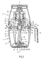
- FIG. 1 A food preparation appliance having a rotary working attachment for the preparation of beverages according to the present invention is illustrated in FIG.
- the food preparation appliance shown in FIG. 1 comprises a lower part 1, comprising a working receptacle 3 and a rotary working attachment 4, and an upper part 2 comprising a cup 5 and a motor housing 6.
- the working receptacle 3 has a bottom 10 and a side wall 11 provided with a handle 12 and a spout 13. Ribs 14 are distributed on the inner face of the side wall 11. The inner face of the side wall 11 has a recess 15 above the ribs 14.
- the working container 3 has an upper edge 16 of cylindrical geometry, with a notch 17 above the spout 13.
- a slip ring 18 is disposed under the bottom 10.
- a guiding element 19 is arranged on the bottom 10 of the working receptacle 3.
- the cup 5 is independent of the motor housing 6.
- the cup 5 comprises a part 20 having an opening 21 provided for the passage of the upper end of the rotary working attachment 4.
- the part 20 comprises a lower annular groove 22 provided for
- the seal 23 is integral with the cup 5.
- the seal 23 has a tubular upper portion 24 mounted in the cup 5. More particularly, the tubular upper portion 24 is removably mounted in the lower annular groove 22 of the workpiece. 20.
- the seal 23 has a deformable annular lip 25.
- the annular lip 25 extends outwards.
- the hardness of the seal 23 is adapted to the weight of the upper part 2 and to the effort required for the control of the apparatus. Shore hardness is for example between 40 and 50 shore.
- the seal 23 is for example made of silicone.
- the motor housing 6 includes a motor 30 associated with drive means 31 of the rotary working implement 4. As shown in FIG. 1, the drive is a direct drive.
- the rotary working attachment 4 comprises a hub 40 having a drive member 41 at the upper end and a centering member 42 at the lower end.
- the centering member 42 is for example formed by a bearing 43 mounted in a cavity 44 of the lower end of the hub 40, designed to cooperate with the guide member 19 of the working receptacle 3.
- the bearing 43 allows speeds rotation of the rotary working implement 4 to approximately 4,000 to 8,000 rpm.
- the rotary working attachment 4 comprises a flange 45 extending below the opening 21 formed on the lower face of the upper part 2, to protect the opening 21 of food projections.
- the rotary working accessory 4 comprises a peripheral protrusion 46 arranged on the lower part of the hub 40.
- the peripheral protrusion 46 forms a disc.
- the peripheral protuberance 46 has an upper face 47, visible in Figure 2, and a lower face 48, visible in Figure 3.
- Two orifices 49, 50 connect the lower face 48 to the upper face 47.
- protruding portions 61, 62, 63, 64 extend outwardly of the peripheral protrusion 46. More particularly, the projections 61, 62, 63, 64 extend from the periphery of the peripheral protrusion 46.
- the projections 61, 62, 63, 64 are preferably metallic.
- the projections 61, 62, 63, 64 have a leading edge 71, 72, 73, 74.
- the leading edges 71, 72, 73, 74 are advantageously non-sharp. Leading edges 71, 72, 73, 74 preferably have teeth.
- the projecting portions 62, 64 are inclined upwardly from the peripheral protuberance 46.
- the projecting portions 61, 63 are inclined downwardly from the peripheral protrusion 46.
- the projecting portions 62, 64 are inclined upwards and protruding parts 61, 63 inclined downwards are arranged alternately around the protuberance 46.
- the protruding parts 61, 62, 63, 64 come from two parts 65, 66, each part 65, 66 having one of the projecting parts 64, 62 inclined upwards and one of the projecting parts 61, 63 inclined downwards.
- the peripheral protuberance 46 has a lower peripheral rib 51.
- the peripheral protuberance 46 has a lower annular zone 56 arranged between the lower peripheral rib 51 and the centering element 42.
- Two lower radial ribs 52, 53 are arranged in the lower annular zone 56.
- the lower radial ribs 52, 53 are offset with respect to the axis of rotation 7 of the rotary working attachment 4.
- the lower radial ribs 52, 53 have an inner end 54, 55 decreasing in height.
- the lower radial ribs 52, 53 form salient conformations 69 having a leading face 70.
- the lower annular zone 56 has two bosses 67, 68 and two cavities 57, 58.
- the bosses 67, 68 correspond to the passage of the parts 65, 66 in the peripheral protrusion 46.
- the lower radial ribs 52, 53 are arranged on the bosses 67 , 68.
- the orifices 49, 50 are arranged in the bosses 67, 68.
- the orifices 49, 50 make it possible, in particular, to facilitate the centering of the parts 65, 66 in their mold during an over-molding of the hub 40 on the parts 65, 66.
- the distance between the lower face 48 of the peripheral protrusion 46 and the bottom 10 of the working receptacle 3 is preferably between 5 and 10 mm.
- the present invention operates as follows.
- the user sets up the rotary working attachment 4 in the working receptacle 3, pours or disposes the food materials in the working receptacle 3, sets up the cup 5 and the motor housing 6, and starts the machine. 'apparatus.
- Solid parts such as ice cubes are crushed by the protruding parts 61, 62, 63, 64.
- the protruding conformations 69 of the lower annular zone 56 of the peripheral protrusion 46 and the projections 61, 62, 63, 64 allow the mixing of the liquid.
- the protruding conformations 69 associated with the bosses 67, 68, the cavities 57, 58, the orifices 49, 50 and the lower peripheral rib 51 favor the production of an emulsion.
- a homogeneous preparation incorporating ice particles can thus be obtained easily and quickly.
- the projecting parts 61, 62, 63, 64 are not necessarily four in number. At least two projecting portions extend outside the peripheral protuberance 46.
- one of the projecting parts is inclined upwards from the peripheral protuberance and another projecting part is inclined downwards from the peripheral protuberance.
- the projecting portions 61, 62, 63, 64 do not necessarily extend from the periphery of the peripheral protrusion 46, while extending outwardly from the peripheral protrusion 46 in a direction to less partially radial with respect to the axis of rotation 7.
- the peripheral protuberance 46 comprises at least one protruding conformation 69.
- the peripheral protuberance 46 has a lower annular zone 56 with less a boss and at least one cavity.
- At least one orifice connects the lower face 48 to the upper face 47.
- the drive means 31 do not necessarily belong to a motor housing, but may for example belong to a cover closing the working receptacle 3 and be driven by a motor housing independent of said cover.
- the guide element 19 is not necessarily derived from bottom of the working container 1, but may for example belong to a base movable in rotation relative to the hub, as described for example in the document FR 2 743 710 or the document FR 2 768 608.
- the guide member 19 n ' is not necessarily formed by a metal axis, but may for example be formed by the bottom of the working container 1 or the aforementioned base.
- the drive member 41 is not necessarily provided on the upper end of the hub 40 and the centering member 42 is not necessarily arranged on the lower end of the hub 40.
- centering member arranged on the upper end of the hub can cooperate with a guide member mounted in a cover closing a working container, a drive device arranged in the bottom of the working container cooperating with a drive member arranged on the lower end of the hub.
Landscapes
- Engineering & Computer Science (AREA)
- Mechanical Engineering (AREA)
- Food Science & Technology (AREA)
- Food-Manufacturing Devices (AREA)
- Mixers Of The Rotary Stirring Type (AREA)
- Non-Alcoholic Beverages (AREA)
- Confectionery (AREA)
- Bakery Products And Manufacturing Methods Therefor (AREA)
Claims (14)
- Rotierendes Arbeitszubehörteil für ein Elektrohaushaltsgerät zur Nahrungsmittelzubereitung, mit einer ein Antriebsorgan (41) aufweisenden Nabe (40) und mindestens zwei hervorstehenden Abschnitten (61, 62, 63, 64), die sich ausgehend von der Nabe (40) erstrecken, wobei ein Umfangsvorsprung (46) am unteren Abschnitt der Nabe (40) ausgebildet ist, wobei sich die hervorstehenden Abschnitte (61, 62, 63, 64) außerhalb des Umfangsvorsprungs (46) erstrecken, wobei der Umfangsvorsprung (46) eine untere Fläche (48) aufweist, die einen ringförmigen unteren Bereich (56) mit mindestens einer hervorstehenden Form (69) besitzt, welche eine Angriffsfläche (70) aufweist, wobei mindestens eine Öffnung (49, 50) die untere Fläche (48) mit einer oberen Fläche (47) des Umfangsvorsprungs (46) verbindet, dadurch gekennzeichnet, dass die Öffnung (49, 50) freiliegt.
- Rotierendes Arbeitszubehörteil nach Anspruch 1, dadurch gekennzeichnet, dass die hervorstehende Form oder mindestens eine der hervorstehenden Formen (69) durch eine radiale untere Rippe (52, 53) gebildet ist.
- Rotierendes Arbeitszubehörteil nach Anspruch 1 oder 2, dadurch gekennzeichnet, dass die hervorstehenden Abschnitte (61, 62, 63, 64) metallisch sind.
- Rotierendes Arbeitszubehörteil nach einem der Ansprüche 1 bis 3, dadurch gekennzeichnet, dass die hervorstehenden Abschnitte (61, 62, 63, 64) eine nicht schneidende Angriffskante (71, 72, 73, 74) aufweisen.
- Rotierendes Arbeitszubehörteil nach einem der Ansprüche 1 bis 4, dadurch gekennzeichnet, dass die hervorstehenden Abschnitte (61, 62, 63, 64) eine mit Zähnen versehene Angriffskante (71, 72, 73, 74) aufweisen.
- Rotierendes Arbeitszubehörteil nach einem der Ansprüche 1 bis 5, dadurch gekennzeichnet, dass einer der hervorstehenden Abschnitte (62, 64) ausgehend von dem Umfangsvorsprung (46) nach oben geneigt ist und ein anderer der hervorstehenden Abschnitte (61, 63) ausgehend von dem Umfangsvorsprung (46) nach unten geneigt ist.
- Rotierendes Arbeitszubehörteil nach Anspruch 6, dadurch gekennzeichnet, dass es vier hervorstehende Abschnitte (61, 62, 63, 64) aufweist, wobei zwei der hervorstehenden Abschnitte (62, 64) nach oben geneigt und die beiden anderen hervorstehenden Abschnitte (61, 63) nach unten geneigt sind, wobei die nach oben geneigten hervorstehenden Abschnitte (62, 64) und die nach unten geneigten hervorstehenden Abschnitte (61, 63) abwechselnd um den Vorsprung (46) angeordnet sind.
- Rotierendes Arbeitszubehörteil nach Anspruch 7, dadurch gekennzeichnet, dass die hervorstehenden Abschnitte (61, 62, 63, 64) aus zwei Teilen (65, 66) hervorgehen, wobei jedes Teil (65, 66) einen der nach oben geneigten hervorstehenden Abschnitte (62, 64) und einen der nach unten geneigten hervorstehenden Abschnitte (61, 63) aufweist.
- Rotierendes Arbeitszubehörteil nach einem der Ansprüche 1 bis 8, dadurch gekennzeichnet, dass der Umfangsvorsprung (46) eine Scheibe bildet.
- Rotierendes Arbeitszubehörteil nach einem der Ansprüche 1 bis 9, dadurch gekennzeichnet, dass eine untere Umfangsrippe (51) den ringförmigen unteren Bereich (56) umgibt.
- Rotierendes Arbeitszubehörteil nach einem der Ansprüche 1 bis 10, dadurch gekennzeichnet, dass mindestens eine Erhebung (67, 68) und mindestens eine Vertiefung (57, 58) am ringförmigen unteren Bereich (56) ausgebildet sind.
- Rotierendes Arbeitszubehörteil nach Anspruch 11, dadurch gekennzeichnet, dass die Öffnung oder mindestens eine der Öffnungen (49, 50) in der Erhebung oder in einer der Erhebungen (67, 68) ausgebildet ist.
- Rotierendes Arbeitszubehörteil nach Anspruch 11 oder 12, dadurch gekennzeichnet, dass die hervorstehende(n) Form(en) (69) an der Erhebung oder an einer der Erhebungen (67, 68) ausgebildet ist (sind).
- Rotierendes Arbeitszubehörteil nach einem der Ansprüche 1 bis 13, dadurch gekennzeichnet, dass der ringförmige untere Bereich (56) ein Zentrierungsorgan (42) umgibt.
Applications Claiming Priority (2)
| Application Number | Priority Date | Filing Date | Title |
|---|---|---|---|
| FR0306859 | 2003-06-06 | ||
| FR0306859A FR2855739B1 (fr) | 2003-06-06 | 2003-06-06 | Accessoire de travail rotatif pour la preparation de boissons dans un appareil electromenager de preparation culinaire. |
Publications (2)
| Publication Number | Publication Date |
|---|---|
| EP1483997A1 EP1483997A1 (de) | 2004-12-08 |
| EP1483997B1 true EP1483997B1 (de) | 2006-11-29 |
Family
ID=33155667
Family Applications (1)
| Application Number | Title | Priority Date | Filing Date |
|---|---|---|---|
| EP04356085A Expired - Lifetime EP1483997B1 (de) | 2003-06-06 | 2004-06-02 | Rotierende Arbeitsvorrichtung zur Zubereitung von Getränken in einem Küchengerät |
Country Status (4)
| Country | Link |
|---|---|
| EP (1) | EP1483997B1 (de) |
| AT (1) | ATE346530T1 (de) |
| DE (1) | DE602004003423T2 (de) |
| FR (1) | FR2855739B1 (de) |
Cited By (1)
| Publication number | Priority date | Publication date | Assignee | Title |
|---|---|---|---|---|
| USD1008735S1 (en) | 2020-12-31 | 2023-12-26 | Sharkninja Operating Llc | Blade for a micro puree machine |
Families Citing this family (11)
| Publication number | Priority date | Publication date | Assignee | Title |
|---|---|---|---|---|
| FR2895893B1 (fr) * | 2006-01-10 | 2011-12-09 | Seb Sa | Accessoire de preparation culinaire a outil rotatif prevu pour etre utilise avec un boitier moteur rapporte |
| FR2986409B1 (fr) * | 2012-02-06 | 2014-09-26 | Seb Sa | Appareil electromenager de preparation culinaire prevu pour etre tenu a la main |
| FR2986410B1 (fr) * | 2012-02-06 | 2014-02-21 | Seb Sa | Appareil electromenager de preparation culinaire prevu pour etre tenu a la main comportant un element de facade rapporte |
| EP2859825B1 (de) * | 2013-10-08 | 2019-03-20 | BSH Hausgeräte GmbH | Motorisiertes Haushaltsgerät zur Nahrungszubereitung |
| FR3064903B1 (fr) * | 2017-04-07 | 2019-06-28 | Seb S.A. | Outil de travail rotatif pour le broyage d'aliments, et accessoire de preparation culinaire comportant un tel outil de travail rotatif |
| US11871765B2 (en) * | 2020-12-31 | 2024-01-16 | Sharkninja Operating Llc | Micro puree machine |
| US12064056B2 (en) | 2020-12-31 | 2024-08-20 | Sharkninja (Hong Kong) Company Limited | Micro puree machine |
| US12016493B2 (en) | 2020-12-31 | 2024-06-25 | Sharkninja Operating Llc | Micro puree machine |
| US12016496B2 (en) | 2020-12-31 | 2024-06-25 | Sharkninja Operating Llc | Micro puree machine |
| US11925298B2 (en) | 2020-12-31 | 2024-03-12 | Sharkninja Operating Llc | Micro puree machine |
| USD985334S1 (en) | 2020-12-31 | 2023-05-09 | Sharkninja Operating Llc | Nested bowl for a micro puree machine |
Family Cites Families (5)
| Publication number | Priority date | Publication date | Assignee | Title |
|---|---|---|---|---|
| US4723719A (en) * | 1986-12-23 | 1988-02-09 | Cuisinarts, Inc. | Invertible/reversible tool for use in a rotary food processing appliance |
| US4813624A (en) * | 1987-08-14 | 1989-03-21 | Cuisinarts, Inc. | Overhead releasable elevating spindle drive for a rotary food processing tool |
| FR2759568B1 (fr) * | 1997-02-18 | 1999-04-02 | Seb Sa | Appareil electromenager de preparation culinaire, du genre robot menager multi-usages, et recipient de travail multi-usages |
| DE19732261C2 (de) * | 1997-07-26 | 2002-02-07 | Braun Gmbh | Zerkleinerungsgerät mit Unterdruck-Vorrichtung |
| DE10013250A1 (de) * | 2000-03-17 | 2001-09-27 | Braun Gmbh | Bearbeitungsbehälter für Nahrungsmittel |
-
2003
- 2003-06-06 FR FR0306859A patent/FR2855739B1/fr not_active Expired - Fee Related
-
2004
- 2004-06-02 DE DE602004003423T patent/DE602004003423T2/de not_active Expired - Lifetime
- 2004-06-02 EP EP04356085A patent/EP1483997B1/de not_active Expired - Lifetime
- 2004-06-02 AT AT04356085T patent/ATE346530T1/de not_active IP Right Cessation
Cited By (1)
| Publication number | Priority date | Publication date | Assignee | Title |
|---|---|---|---|---|
| USD1008735S1 (en) | 2020-12-31 | 2023-12-26 | Sharkninja Operating Llc | Blade for a micro puree machine |
Also Published As
| Publication number | Publication date |
|---|---|
| DE602004003423D1 (de) | 2007-01-11 |
| ATE346530T1 (de) | 2006-12-15 |
| FR2855739B1 (fr) | 2006-02-17 |
| FR2855739A1 (fr) | 2004-12-10 |
| EP1483997A1 (de) | 2004-12-08 |
| DE602004003423T2 (de) | 2007-09-27 |
Similar Documents
| Publication | Publication Date | Title |
|---|---|---|
| US9107539B2 (en) | Food processor | |
| EP2408598B1 (de) | Mehrfunktionsgerät für kulinarische zubereitung und/oder gerät zum kontinuierlichen schneiden von lebensmitteln | |
| EP1483997A1 (de) | Rotierende Arbeitsvorrichtung zur Zubereitung von Getränken in einem Küchengerät | |
| EP0328590B2 (de) | Zusatzbehälter für küchenmaschinen | |
| EP2429363B1 (de) | Kompaktes kochgerät, im besonderen zur herstellung von sojamilch | |
| EP2892405B1 (de) | Haushaltsvorrichtung zur lebensmittelherstellung mit einem haken zur teigmischung durch planetengetriebebewegungen | |
| FR2967035A1 (fr) | Appareil electromenager de preparation culinaire comportant une vis de pressage et un element de filtration | |
| EP1139838B1 (de) | Mehrzweckküchenmaschine | |
| EP0961570A1 (de) | Elektrisches haushaltsgerät zur nahrungszubereitung in der art einer vielzweckküchenmaschine, und vielzweckkarbeitsbehälter | |
| EP2522262A1 (de) | Mixinstrument für Arbeitsbehälter eines Elektrohaushaltsgerätes zur Speisenzubereitung | |
| EP0071496B1 (de) | Gerät zum Zubereiten von Mayonnaisen oder ähnlichen Emulsionen | |
| EP0043773A1 (de) | Gerät zum Behandeln von Nahrungsmitteln, insbesondere von teigförmigen Massen | |
| EP3774010B1 (de) | Mischwerkzeug für eine lebensmittelzubereitungsvorrichtung | |
| CN113163989B (zh) | 用于加工食品的器具 | |
| FR2707187A1 (fr) | Lame de coupe, notamment applicable sur des appareils du type appareil de préparation culinaire. | |
| EP0189512B1 (de) | Schlag- und Emulgierwerkzeug für elektrische Küchenmaschine zum Zubereiten von Nahrungsmitteln | |
| FR2745166A1 (fr) | Appareil menager a couteau rotatif, tel qu'un hachoir | |
| EP1051100B1 (de) | Küchenmaschine mit oberhalb angeordnetem motor | |
| EP3424382B1 (de) | Emulsion haushaltsgerät zur essenszubereitung | |
| EP2923620B1 (de) | Vorrichtung zur lebensmittelzubereitung, die einen abnehmbaren sockel umfasst, der als deckel für die konservierung verwendet werden kann | |
| JP3103644U (ja) | 食品の切削調理機 | |
| EP1809155B1 (de) | Elektrisches haushaltsgerät zur herstellung von lebensmitteln mit einer basis mit verschieden geformten aussparungen | |
| FR3021516A1 (fr) | Dispositif de preparation d’aliments adapte a l’extraction de jus et/ou de coulis | |
| FR3045305A1 (fr) | Appareil de traitement des aliments | |
| JP2002165711A (ja) | ミキサー |
Legal Events
| Date | Code | Title | Description |
|---|---|---|---|
| PUAI | Public reference made under article 153(3) epc to a published international application that has entered the european phase |
Free format text: ORIGINAL CODE: 0009012 |
|
| AK | Designated contracting states |
Kind code of ref document: A1 Designated state(s): AT BE BG CH CY CZ DE DK EE ES FI FR GB GR HU IE IT LI LU MC NL PL PT RO SE SI SK TR |
|
| AX | Request for extension of the european patent |
Extension state: AL HR LT LV MK |
|
| 17P | Request for examination filed |
Effective date: 20050601 |
|
| AKX | Designation fees paid |
Designated state(s): AT BE BG CH CY CZ DE DK EE ES FI FR GB GR HU IE IT LI LU MC NL PL PT RO SE SI SK TR |
|
| GRAP | Despatch of communication of intention to grant a patent |
Free format text: ORIGINAL CODE: EPIDOSNIGR1 |
|
| GRAS | Grant fee paid |
Free format text: ORIGINAL CODE: EPIDOSNIGR3 |
|
| GRAA | (expected) grant |
Free format text: ORIGINAL CODE: 0009210 |
|
| AK | Designated contracting states |
Kind code of ref document: B1 Designated state(s): AT BE BG CH CY CZ DE DK EE ES FI FR GB GR HU IE IT LI LU MC NL PL PT RO SE SI SK TR |
|
| PG25 | Lapsed in a contracting state [announced via postgrant information from national office to epo] |
Ref country code: CZ Free format text: LAPSE BECAUSE OF FAILURE TO SUBMIT A TRANSLATION OF THE DESCRIPTION OR TO PAY THE FEE WITHIN THE PRESCRIBED TIME-LIMIT Effective date: 20061129 Ref country code: IE Free format text: LAPSE BECAUSE OF FAILURE TO SUBMIT A TRANSLATION OF THE DESCRIPTION OR TO PAY THE FEE WITHIN THE PRESCRIBED TIME-LIMIT Effective date: 20061129 Ref country code: NL Free format text: LAPSE BECAUSE OF FAILURE TO SUBMIT A TRANSLATION OF THE DESCRIPTION OR TO PAY THE FEE WITHIN THE PRESCRIBED TIME-LIMIT Effective date: 20061129 Ref country code: FI Free format text: LAPSE BECAUSE OF FAILURE TO SUBMIT A TRANSLATION OF THE DESCRIPTION OR TO PAY THE FEE WITHIN THE PRESCRIBED TIME-LIMIT Effective date: 20061129 Ref country code: SK Free format text: LAPSE BECAUSE OF FAILURE TO SUBMIT A TRANSLATION OF THE DESCRIPTION OR TO PAY THE FEE WITHIN THE PRESCRIBED TIME-LIMIT Effective date: 20061129 Ref country code: AT Free format text: LAPSE BECAUSE OF FAILURE TO SUBMIT A TRANSLATION OF THE DESCRIPTION OR TO PAY THE FEE WITHIN THE PRESCRIBED TIME-LIMIT Effective date: 20061129 Ref country code: RO Free format text: LAPSE BECAUSE OF FAILURE TO SUBMIT A TRANSLATION OF THE DESCRIPTION OR TO PAY THE FEE WITHIN THE PRESCRIBED TIME-LIMIT Effective date: 20061129 Ref country code: PL Free format text: LAPSE BECAUSE OF FAILURE TO SUBMIT A TRANSLATION OF THE DESCRIPTION OR TO PAY THE FEE WITHIN THE PRESCRIBED TIME-LIMIT Effective date: 20061129 Ref country code: SI Free format text: LAPSE BECAUSE OF FAILURE TO SUBMIT A TRANSLATION OF THE DESCRIPTION OR TO PAY THE FEE WITHIN THE PRESCRIBED TIME-LIMIT Effective date: 20061129 |
|
| REG | Reference to a national code |
Ref country code: GB Ref legal event code: FG4D Free format text: NOT ENGLISH |
|
| REG | Reference to a national code |
Ref country code: CH Ref legal event code: EP |
|
| REG | Reference to a national code |
Ref country code: IE Ref legal event code: FG4D Free format text: LANGUAGE OF EP DOCUMENT: FRENCH |
|
| REF | Corresponds to: |
Ref document number: 602004003423 Country of ref document: DE Date of ref document: 20070111 Kind code of ref document: P |
|
| GBT | Gb: translation of ep patent filed (gb section 77(6)(a)/1977) |
Effective date: 20070131 |
|
| PG25 | Lapsed in a contracting state [announced via postgrant information from national office to epo] |
Ref country code: SE Free format text: LAPSE BECAUSE OF FAILURE TO SUBMIT A TRANSLATION OF THE DESCRIPTION OR TO PAY THE FEE WITHIN THE PRESCRIBED TIME-LIMIT Effective date: 20070228 Ref country code: DK Free format text: LAPSE BECAUSE OF FAILURE TO SUBMIT A TRANSLATION OF THE DESCRIPTION OR TO PAY THE FEE WITHIN THE PRESCRIBED TIME-LIMIT Effective date: 20070228 Ref country code: BG Free format text: LAPSE BECAUSE OF FAILURE TO SUBMIT A TRANSLATION OF THE DESCRIPTION OR TO PAY THE FEE WITHIN THE PRESCRIBED TIME-LIMIT Effective date: 20070228 |
|
| PG25 | Lapsed in a contracting state [announced via postgrant information from national office to epo] |
Ref country code: ES Free format text: LAPSE BECAUSE OF FAILURE TO SUBMIT A TRANSLATION OF THE DESCRIPTION OR TO PAY THE FEE WITHIN THE PRESCRIBED TIME-LIMIT Effective date: 20070312 |
|
| PG25 | Lapsed in a contracting state [announced via postgrant information from national office to epo] |
Ref country code: PT Free format text: LAPSE BECAUSE OF FAILURE TO SUBMIT A TRANSLATION OF THE DESCRIPTION OR TO PAY THE FEE WITHIN THE PRESCRIBED TIME-LIMIT Effective date: 20070430 |
|
| NLV1 | Nl: lapsed or annulled due to failure to fulfill the requirements of art. 29p and 29m of the patents act | ||
| REG | Reference to a national code |
Ref country code: IE Ref legal event code: FD4D |
|
| PLBE | No opposition filed within time limit |
Free format text: ORIGINAL CODE: 0009261 |
|
| STAA | Information on the status of an ep patent application or granted ep patent |
Free format text: STATUS: NO OPPOSITION FILED WITHIN TIME LIMIT |
|
| 26N | No opposition filed |
Effective date: 20070830 |
|
| PG25 | Lapsed in a contracting state [announced via postgrant information from national office to epo] |
Ref country code: MC Free format text: LAPSE BECAUSE OF NON-PAYMENT OF DUE FEES Effective date: 20070630 |
|
| PG25 | Lapsed in a contracting state [announced via postgrant information from national office to epo] |
Ref country code: GR Free format text: LAPSE BECAUSE OF FAILURE TO SUBMIT A TRANSLATION OF THE DESCRIPTION OR TO PAY THE FEE WITHIN THE PRESCRIBED TIME-LIMIT Effective date: 20070301 |
|
| PGFP | Annual fee paid to national office [announced via postgrant information from national office to epo] |
Ref country code: GB Payment date: 20080604 Year of fee payment: 5 |
|
| PG25 | Lapsed in a contracting state [announced via postgrant information from national office to epo] |
Ref country code: EE Free format text: LAPSE BECAUSE OF FAILURE TO SUBMIT A TRANSLATION OF THE DESCRIPTION OR TO PAY THE FEE WITHIN THE PRESCRIBED TIME-LIMIT Effective date: 20061129 |
|
| REG | Reference to a national code |
Ref country code: CH Ref legal event code: PL |
|
| PG25 | Lapsed in a contracting state [announced via postgrant information from national office to epo] |
Ref country code: CH Free format text: LAPSE BECAUSE OF NON-PAYMENT OF DUE FEES Effective date: 20080630 Ref country code: LI Free format text: LAPSE BECAUSE OF NON-PAYMENT OF DUE FEES Effective date: 20080630 |
|
| PG25 | Lapsed in a contracting state [announced via postgrant information from national office to epo] |
Ref country code: CY Free format text: LAPSE BECAUSE OF FAILURE TO SUBMIT A TRANSLATION OF THE DESCRIPTION OR TO PAY THE FEE WITHIN THE PRESCRIBED TIME-LIMIT Effective date: 20061129 Ref country code: LU Free format text: LAPSE BECAUSE OF NON-PAYMENT OF DUE FEES Effective date: 20070602 |
|
| PG25 | Lapsed in a contracting state [announced via postgrant information from national office to epo] |
Ref country code: HU Free format text: LAPSE BECAUSE OF FAILURE TO SUBMIT A TRANSLATION OF THE DESCRIPTION OR TO PAY THE FEE WITHIN THE PRESCRIBED TIME-LIMIT Effective date: 20070530 Ref country code: TR Free format text: LAPSE BECAUSE OF FAILURE TO SUBMIT A TRANSLATION OF THE DESCRIPTION OR TO PAY THE FEE WITHIN THE PRESCRIBED TIME-LIMIT Effective date: 20061129 |
|
| GBPC | Gb: european patent ceased through non-payment of renewal fee |
Effective date: 20090602 |
|
| PG25 | Lapsed in a contracting state [announced via postgrant information from national office to epo] |
Ref country code: GB Free format text: LAPSE BECAUSE OF NON-PAYMENT OF DUE FEES Effective date: 20090602 |
|
| PGFP | Annual fee paid to national office [announced via postgrant information from national office to epo] |
Ref country code: DE Payment date: 20130611 Year of fee payment: 10 |
|
| PGFP | Annual fee paid to national office [announced via postgrant information from national office to epo] |
Ref country code: IT Payment date: 20130619 Year of fee payment: 10 |
|
| PGFP | Annual fee paid to national office [announced via postgrant information from national office to epo] |
Ref country code: BE Payment date: 20130626 Year of fee payment: 10 |
|
| REG | Reference to a national code |
Ref country code: DE Ref legal event code: R119 Ref document number: 602004003423 Country of ref document: DE |
|
| REG | Reference to a national code |
Ref country code: DE Ref legal event code: R119 Ref document number: 602004003423 Country of ref document: DE Effective date: 20150101 |
|
| PG25 | Lapsed in a contracting state [announced via postgrant information from national office to epo] |
Ref country code: DE Free format text: LAPSE BECAUSE OF NON-PAYMENT OF DUE FEES Effective date: 20150101 Ref country code: IT Free format text: LAPSE BECAUSE OF NON-PAYMENT OF DUE FEES Effective date: 20140602 |
|
| REG | Reference to a national code |
Ref country code: FR Ref legal event code: PLFP Year of fee payment: 12 |
|
| REG | Reference to a national code |
Ref country code: FR Ref legal event code: PLFP Year of fee payment: 13 |
|
| PGFP | Annual fee paid to national office [announced via postgrant information from national office to epo] |
Ref country code: FR Payment date: 20160708 Year of fee payment: 13 |
|
| REG | Reference to a national code |
Ref country code: FR Ref legal event code: CA Effective date: 20170322 |
|
| PG25 | Lapsed in a contracting state [announced via postgrant information from national office to epo] |
Ref country code: BE Free format text: LAPSE BECAUSE OF NON-PAYMENT OF DUE FEES Effective date: 20140630 |
|
| REG | Reference to a national code |
Ref country code: FR Ref legal event code: ST Effective date: 20180228 |
|
| PG25 | Lapsed in a contracting state [announced via postgrant information from national office to epo] |
Ref country code: FR Free format text: LAPSE BECAUSE OF NON-PAYMENT OF DUE FEES Effective date: 20170630 |