EP1484083A1 - Méthode et appareil de réglage de stimulateur physiologique - Google Patents
Méthode et appareil de réglage de stimulateur physiologique Download PDFInfo
- Publication number
- EP1484083A1 EP1484083A1 EP04253249A EP04253249A EP1484083A1 EP 1484083 A1 EP1484083 A1 EP 1484083A1 EP 04253249 A EP04253249 A EP 04253249A EP 04253249 A EP04253249 A EP 04253249A EP 1484083 A1 EP1484083 A1 EP 1484083A1
- Authority
- EP
- European Patent Office
- Prior art keywords
- evaluating
- stimulation
- act
- pacemaker
- stimulation device
- Prior art date
- Legal status (The legal status is an assumption and is not a legal conclusion. Google has not performed a legal analysis and makes no representation as to the accuracy of the status listed.)
- Granted
Links
- 238000000034 method Methods 0.000 title claims abstract description 103
- 238000002489 impedance cardiography Methods 0.000 claims abstract description 87
- 230000004217 heart function Effects 0.000 claims abstract description 10
- 230000000638 stimulation Effects 0.000 claims description 68
- 230000000747 cardiac effect Effects 0.000 claims description 32
- 238000012545 processing Methods 0.000 claims description 31
- 238000001514 detection method Methods 0.000 claims description 25
- 238000011156 evaluation Methods 0.000 claims description 16
- 238000004891 communication Methods 0.000 claims description 11
- 230000006870 function Effects 0.000 claims description 11
- 210000003484 anatomy Anatomy 0.000 claims description 8
- 230000004936 stimulating effect Effects 0.000 claims description 6
- 230000009471 action Effects 0.000 claims description 4
- 238000002513 implantation Methods 0.000 claims description 2
- 238000011065 in-situ storage Methods 0.000 claims description 2
- 238000013155 cardiography Methods 0.000 claims 1
- 230000001976 improved effect Effects 0.000 abstract description 16
- 238000005259 measurement Methods 0.000 abstract description 14
- 206010027727 Mitral valve incompetence Diseases 0.000 abstract description 10
- 238000005457 optimization Methods 0.000 description 27
- 238000000718 qrs complex Methods 0.000 description 13
- 230000002861 ventricular Effects 0.000 description 13
- 230000008569 process Effects 0.000 description 12
- 238000004458 analytical method Methods 0.000 description 11
- 210000001765 aortic valve Anatomy 0.000 description 9
- 238000013459 approach Methods 0.000 description 8
- 230000008602 contraction Effects 0.000 description 8
- 210000001519 tissue Anatomy 0.000 description 8
- 238000012544 monitoring process Methods 0.000 description 7
- 210000000115 thoracic cavity Anatomy 0.000 description 7
- 210000005241 right ventricle Anatomy 0.000 description 6
- 238000003491 array Methods 0.000 description 5
- 230000001746 atrial effect Effects 0.000 description 5
- 230000000694 effects Effects 0.000 description 5
- 210000000038 chest Anatomy 0.000 description 4
- 238000010586 diagram Methods 0.000 description 4
- 238000005516 engineering process Methods 0.000 description 4
- 210000005240 left ventricle Anatomy 0.000 description 4
- 230000000717 retained effect Effects 0.000 description 4
- 210000005245 right atrium Anatomy 0.000 description 4
- 102000038012 SFKs Human genes 0.000 description 3
- 108091008118 SFKs Proteins 0.000 description 3
- 230000008859 change Effects 0.000 description 3
- 238000002592 echocardiography Methods 0.000 description 3
- 230000001965 increasing effect Effects 0.000 description 3
- 210000004115 mitral valve Anatomy 0.000 description 3
- 230000004044 response Effects 0.000 description 3
- 238000003860 storage Methods 0.000 description 3
- 238000001356 surgical procedure Methods 0.000 description 3
- 238000012360 testing method Methods 0.000 description 3
- 206010006580 Bundle branch block left Diseases 0.000 description 2
- 206010006578 Bundle-Branch Block Diseases 0.000 description 2
- 230000036982 action potential Effects 0.000 description 2
- 206010003119 arrhythmia Diseases 0.000 description 2
- 230000006793 arrhythmia Effects 0.000 description 2
- 239000008280 blood Substances 0.000 description 2
- 210000004369 blood Anatomy 0.000 description 2
- 210000003748 coronary sinus Anatomy 0.000 description 2
- 238000013461 design Methods 0.000 description 2
- 230000009977 dual effect Effects 0.000 description 2
- 210000005003 heart tissue Anatomy 0.000 description 2
- 230000000004 hemodynamic effect Effects 0.000 description 2
- 201000001715 left bundle branch hemiblock Diseases 0.000 description 2
- 230000007246 mechanism Effects 0.000 description 2
- 238000010202 multivariate logistic regression analysis Methods 0.000 description 2
- 210000003205 muscle Anatomy 0.000 description 2
- 210000004165 myocardium Anatomy 0.000 description 2
- 230000006855 networking Effects 0.000 description 2
- 241000894007 species Species 0.000 description 2
- 206010042772 syncope Diseases 0.000 description 2
- 208000031229 Cardiomyopathies Diseases 0.000 description 1
- 206010015856 Extrasystoles Diseases 0.000 description 1
- 206010019280 Heart failures Diseases 0.000 description 1
- 208000029578 Muscle disease Diseases 0.000 description 1
- 210000001015 abdomen Anatomy 0.000 description 1
- 230000001154 acute effect Effects 0.000 description 1
- 230000006978 adaptation Effects 0.000 description 1
- 230000002776 aggregation Effects 0.000 description 1
- 238000004220 aggregation Methods 0.000 description 1
- 230000002763 arrhythmic effect Effects 0.000 description 1
- 238000013473 artificial intelligence Methods 0.000 description 1
- 210000001992 atrioventricular node Anatomy 0.000 description 1
- 230000006399 behavior Effects 0.000 description 1
- 230000008901 benefit Effects 0.000 description 1
- 230000005540 biological transmission Effects 0.000 description 1
- 230000017531 blood circulation Effects 0.000 description 1
- 230000036772 blood pressure Effects 0.000 description 1
- 210000004375 bundle of his Anatomy 0.000 description 1
- 210000005242 cardiac chamber Anatomy 0.000 description 1
- 230000004087 circulation Effects 0.000 description 1
- 230000000052 comparative effect Effects 0.000 description 1
- 230000003247 decreasing effect Effects 0.000 description 1
- 230000007547 defect Effects 0.000 description 1
- 230000001934 delay Effects 0.000 description 1
- 238000009795 derivation Methods 0.000 description 1
- 230000004069 differentiation Effects 0.000 description 1
- 230000005684 electric field Effects 0.000 description 1
- 238000002565 electrocardiography Methods 0.000 description 1
- 210000001174 endocardium Anatomy 0.000 description 1
- 230000005284 excitation Effects 0.000 description 1
- 239000000835 fiber Substances 0.000 description 1
- 238000001914 filtration Methods 0.000 description 1
- 238000005286 illumination Methods 0.000 description 1
- 230000006872 improvement Effects 0.000 description 1
- 230000001939 inductive effect Effects 0.000 description 1
- 230000000977 initiatory effect Effects 0.000 description 1
- 230000003993 interaction Effects 0.000 description 1
- 238000002955 isolation Methods 0.000 description 1
- 210000005246 left atrium Anatomy 0.000 description 1
- 230000005226 mechanical processes and functions Effects 0.000 description 1
- 238000012806 monitoring device Methods 0.000 description 1
- 230000002093 peripheral effect Effects 0.000 description 1
- 230000002685 pulmonary effect Effects 0.000 description 1
- 230000000541 pulsatile effect Effects 0.000 description 1
- 230000034225 regulation of ventricular cardiomyocyte membrane depolarization Effects 0.000 description 1
- 238000012552 review Methods 0.000 description 1
- 230000033764 rhythmic process Effects 0.000 description 1
- 210000001013 sinoatrial node Anatomy 0.000 description 1
- 230000003595 spectral effect Effects 0.000 description 1
- 238000001228 spectrum Methods 0.000 description 1
- 230000007480 spreading Effects 0.000 description 1
- 238000003892 spreading Methods 0.000 description 1
- 238000006467 substitution reaction Methods 0.000 description 1
- 230000009466 transformation Effects 0.000 description 1
- 230000001960 triggered effect Effects 0.000 description 1
- 210000002620 vena cava superior Anatomy 0.000 description 1
- 230000001755 vocal effect Effects 0.000 description 1
Images


Classifications
-
- A—HUMAN NECESSITIES
- A61—MEDICAL OR VETERINARY SCIENCE; HYGIENE
- A61N—ELECTROTHERAPY; MAGNETOTHERAPY; RADIATION THERAPY; ULTRASOUND THERAPY
- A61N1/00—Electrotherapy; Circuits therefor
- A61N1/18—Applying electric currents by contact electrodes
- A61N1/32—Applying electric currents by contact electrodes alternating or intermittent currents
- A61N1/36—Applying electric currents by contact electrodes alternating or intermittent currents for stimulation
- A61N1/362—Heart stimulators
- A61N1/365—Heart stimulators controlled by a physiological parameter, e.g. heart potential
- A61N1/36585—Heart stimulators controlled by a physiological parameter, e.g. heart potential controlled by two or more physical parameters
-
- A—HUMAN NECESSITIES
- A61—MEDICAL OR VETERINARY SCIENCE; HYGIENE
- A61N—ELECTROTHERAPY; MAGNETOTHERAPY; RADIATION THERAPY; ULTRASOUND THERAPY
- A61N1/00—Electrotherapy; Circuits therefor
- A61N1/18—Applying electric currents by contact electrodes
- A61N1/32—Applying electric currents by contact electrodes alternating or intermittent currents
- A61N1/36—Applying electric currents by contact electrodes alternating or intermittent currents for stimulation
- A61N1/372—Arrangements in connection with the implantation of stimulators
- A61N1/37211—Means for communicating with stimulators
- A61N1/37252—Details of algorithms or data aspects of communication system, e.g. handshaking, transmitting specific data or segmenting data
- A61N1/37254—Pacemaker or defibrillator security, e.g. to prevent or inhibit programming alterations by hackers or unauthorised individuals
-
- A—HUMAN NECESSITIES
- A61—MEDICAL OR VETERINARY SCIENCE; HYGIENE
- A61N—ELECTROTHERAPY; MAGNETOTHERAPY; RADIATION THERAPY; ULTRASOUND THERAPY
- A61N1/00—Electrotherapy; Circuits therefor
- A61N1/18—Applying electric currents by contact electrodes
- A61N1/32—Applying electric currents by contact electrodes alternating or intermittent currents
- A61N1/36—Applying electric currents by contact electrodes alternating or intermittent currents for stimulation
- A61N1/372—Arrangements in connection with the implantation of stimulators
- A61N1/37211—Means for communicating with stimulators
- A61N1/37252—Details of algorithms or data aspects of communication system, e.g. handshaking, transmitting specific data or segmenting data
- A61N1/37264—Changing the program; Upgrading firmware
Definitions
- the present invention relates generally to the field of biomedical treatment and analysis, and particularly to an improved apparatus and method for tuning and operating stimulation devices such as pacemakers.
- Physiologic stimulation devices are well known in the medical arts. These devices are used to, inter alia, provide regular or incidental stimulation to the tissue (e.g., muscle or cardiac tissue) of a living subject, typically using electrical current, in order to induce a response in that tissue, such as a contraction of the tissue.
- tissue e.g., muscle or cardiac tissue
- electrical current typically used to induce a response in that tissue, such as a contraction of the tissue.
- One such well known device is the implantable cardiac pacemaker.
- a pacemaker is a device that generally consists of a pulse generator, electrical power source (e.g., battery), and leads or electrodes for passing the generated pulse(s) to the subject's tissue. It produces voltage impulses of short duration to the endocardium or myocardium (heart).
- the electrical leads may be positioned in the right ventricle only (so-called “single chamber” pacing); the right atrium and right ventricle ("dual chamber” pacing); or the right atrium, right ventricle, and left ventricle (“biventricular” pacing).
- an artificial pacing voltage spike generated by the pacemaker excites the relevant cardiac tissue by the creation of an electrical field at the interface of the stimulating electrode and the underlying tissue.
- This excitation initiates a self-regenerating wavefront of action potentials that propagate away from the site of stimulation, leading to contraction of the desired heart chamber (right atrial/ventricular stimulation causes left atrial/ventricular contraction), or coordination of chamber contraction (left and right ventricle interaction).
- a pacemaker is implanted to compensate for a conduction defect that prevents an action potential in the sinoatrial node from being efficiently or completely transmitted to the atrioventricular node, to the His bundle, and to left and right the bundle branches.
- a permanent pacemaker may also be indicated for neurally mediated syncope (fainting) and cardiomyopathy (heart muscle disease).
- the parameter settings of a pacemaker may be customized from the default settings provided with the device using a pacemaker programmer.
- a pacemaker programmer enables both programmability and telemetry of programming commands, administrative data, programmed data, measured data, and diagnostic data. Commands and data are typically transmitted across through an electromagnetic telemetry interface, usually in the form of a hand-held wand or paddle, which is positioned proximate to the pacemaker pulse generator, external to the subject. Communication between the implanted device and the programming device may be continuous, or may require a programmer command to initiate programmer transmission to the pulse generator.
- U. S. Patent No. 5,891,178 to Mann, et al. issued April 6, 1999 and entitled "Programmer system and associated methods for rapidly evaluating and programming an implanted cardiac device" which is incorporated herein by reference in its entirety, describes one such pacemaker programmer and telemetry interface.
- AV atrioventricular
- VV biventricular
- AV atrioventricular
- VV biventricular
- various trial parameter settings are typically programmed and evaluated.
- the parameter setting that produces the highest left ventricular stroke volume is considered the optimal parameter setting.
- echocardiography techniques are used as the means and reference standard for determining left ventricular stroke volume.
- ICG impedance cardiography
- thoracic bioimpedance or impedance plethysmography is used to measure the stroke volume (SV) of the heart.
- SV stroke volume
- ECG electrocardiogram
- the basic method of correlating thoracic, or chest cavity, impedance, Z T (t), with stroke volume was developed by Kubicek, et al. at the University of Minnesota for use by NASA. See, e.g., U.S. Reissue Patent No.
- the method generally comprises modeling the thoracic impedance Z T (t ) as a constant impedance, Z o , and time-varying impedance, ⁇ Z (t).
- the time-varying impedance is measured by way of an impedance waveform derived from electrodes placed on various locations of the subject's thorax; changes in the impedance over time can then be related to the change in fluidic volume (i.e., stroke volume), and ultimately cardiac output via Eqn. (1) above.
- ICG has been proven to be a rapid, effective, and easily administered non-invasive technique for determining the volumetric output of the heart of the human being (or other species).
- an improved apparatus and method for non-invasively tuning and evaluating implantable stimulation devices such as cardiac pacemakers.
- Such improved apparatus and method ideally would allow the clinician to rapidly and accurately tune one or more parameters associated with the stimulation device, including e.g., the aforementioned AV and VV parameters as appropriate. Additionally, the improved apparatus and method would also permit such tuning and operation by relatively unqualified personnel (to prospectively include the subject themselves).
- the present invention satisfies the aforementioned needs by providing an improved method and apparatus for tuning and operating an implantable stimulation device used in conjunction with a living subject.
- an improved method for tuning a biomedical stimulation device such as a pacemaker.
- the method generally comprises evaluating at least one aspect of cardiac function under varied conditions of stimulation produced by the stimulation device; and tuning the stimulation device based at least in part on the act of evaluating.
- the method comprises iteratively varying one or more parameters associated with the pacemaker (e.g., the AV delay or VV skew times), and measuring stroke volume and/or mitral regurgitation (MR) at least once during each iteration using ICG.
- an improved evaluation apparatus for use with a cardiac stimulation device.
- the apparatus generally comprises impedance cardiography apparatus adapted for determining at least one aspect of cardiac function under varied conditions of stimulation produced by the stimulation device.
- the apparatus comprises an ICG module coupled to a pacemaker control apparatus, the latter adapted to control the conditions of said stimulation device through an electromagnetic or inductive interface.
- the evaluation apparatus is further configured to initiate and perform evaluation and tuning through a single user action; e.g., the press of a single button.
- an improved method of operating a cardiac pacemaker implanted within a living subject generally comprises: operating the pacemaker in a first operating condition; measuring a first cardiac parameter using ICG to produce a first value; operating the pacemaker in a second operating condition; measuring the first cardiac parameter using ICG to produce a second value; and evaluating the first and second values for use in subsequent operation.
- the acts of operating, measuring, and evaluating are initiated through a single user action.
- the method comprises automatically iterating at least one parameter associated with the operation of the pacemaker across a plurality of different values, and measuring the value of at least one cardiac parameter using ICG during each iteration; and selectively utilizing at least one of the plurality of different values for subsequent operation of the pacemaker.
- the method comprises evaluating at least one aspect of cardiac function under varied stimulation device settings, the act of evaluating being substantially continuous and performed at least in part using impedance cardiography; and tuning the stimulation device based at least in part on the act of evaluating.
- an improved cardiac evaluation apparatus in a fourth aspect of the invention, generally comprises: a stimulation source adapted to produce a stimulation current; a plurality of electrodes adapted for use on a living subject, at least a portion of the electrodes being further adapted to apply the stimulation current to the subject; a data interface adapted to transmit data between the apparatus and a pacemaker controller configured to control at least one parameter associated with a pacemaker; and a signal processing apparatus operatively coupled to at least a portion of the electrodes and the data interface, the signal processing apparatus adapted to coordinate evaluation of signals obtained from the at least portion of electrodes with changes in the at least one parameter of the pacemaker in order to identify an optimal value thereof.
- an improved method for placing electrical leads associated with a stimulation device generally comprises: disposing at least one lead of the device in physical communication with a portion of a subject's anatomy; stimulating at least a portion of the anatomy using the lead; measuring at least one parameter from said anatomy related to the functioning thereof; and evaluating the act of disposing based at least in part on the act of measuring.
- the device comprises a cardiac pacemaker, and the act of measuring comprises measuring stroke volume from the heart of the subject using ICG as the lead(s) is/are moved in order to find the optimal placement thereof.
- digital processor is meant generally to include all types of digital processing devices including, without limitation, digital signal processors (DSPs), reduced instruction set computers (RISC), general-purpose (CISC) processors, microprocessors, and application-specific integrated circuits (ASICs).
- DSPs digital signal processors
- RISC reduced instruction set computers
- CISC general-purpose processors
- microprocessors microprocessors
- ASICs application-specific integrated circuits
- monitoring device and “monitoring device” are used generally to refer to devices adapted to perform monitoring, display, user interface, and/or control functions. Such devices may be dedicated to a particular function, or multi-purpose devices adaptable to performing a variety of functions and/or interfacing with a number of functional modules.
- stimulation device and “stimulator” refer generally to devices which may be used to stimulate living tissue or muscle to obtain a desired response.
- One exemplary stimulator is the cardiac pacemaker, although it will be recognized that the present invention is not limited to traditional cardiac pacemaker devices alone.
- another exemplary stimulator comprises the implantable cardiovertor-defibrillator, which always incorporates single chamber pacemaker functionality and often dual chamber or biventricular pacing..
- the present invention provides improved methods and apparatus for tuning and operating an implantable stimulation device (e.g., cardiac pacemaker).
- implantable stimulation device e.g., cardiac pacemaker.
- ICG technologies as compared to the prior art echocardiography tuning methods, see Kindermann, et al., PACE, 20[Pt. I ⁇ :2453-2462, 1997), such ICG technologies enabling more rapid pacemaker tuning, with equivalent or even increased accuracy.
- the use of ICG techniques to perform the aforementioned tuning is highly automated to the point where the user or clinician can perform the entire tuning process with little more than the selection of one function (or push of one "button").
- such simplified tuning as offered by the present invention opens up the field of prospective users/operators to even those having little skill or experience in performing such optimizations, including the patient being "tuned" himself.
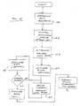
- FIGs. 1-1a the general methodology of non-invasively tuning an implantable stimulation device in a living subject according to the invention is described.
- Fig. 1 illustrates the logical flow of the method of tuning the pacemaker based on stroke volume according to the invention.
- the method 100 generally comprises first providing a plurality of ICG electrodes or electrode "arrays" per step 102. Exemplary electrodes for this purpose are described in, inter alia, the aforementioned U.S. patent application Serial Nos. 09/613,183 entitled “Apparatus And Method For Determining Cardiac Output In A Living Subject” filed July 10, 2000, now U.S. Patent No. 6,636,754 issued October 21, 2003, and 09/903,473 entitled “Apparatus and Method for Determining Cardiac Output in a Living Subject” filed July 10, 2001, now U.S. Patent No.
- the ICG electrodes/arrays are positioned at the desired locations above and below the thoracic cavity of the subject whose pacemaker is to be "tuned" per step 104, as illustrated in Fig. 1 a herein. In one embodiment of the method, these locations are chosen to be on the right and left sides of the abdomen of the subject, and the right and left sides of the neck. Other locations and/or combinations of arrays may be substituted with equal success.
- pacemaker programmer ECG electrodes may also be positioned at the desired locations of right arm, left arm, right leg, and left leg. These pacemaker electrodes provide ECGs that the clinician may view on the pacemaker programmer display. However, because the ECG does not provide information on mechanical function, it cannot be used alone for pacemaker optimization.
- one or more settings or parameters are set to desired values per step 106.
- desired values may be determined according to any number of schemes, including without limitation (i) random selection (such as via a random or pseudorandom number generator which is limited within a range of physically reasonable values); (ii) predetermination based on, e.g., anecdotal or empirical data (such as prior clinical studies); or (iii) deterministic derivation based on measurement/analysis of one or more other physiologic or hemodynamic parameters, such as contemporaneous measurement of blood pressure, and the like.
- these settings or values may be resident within the pacemaker itself (such as being prestored within a storage device of the pacemaker), or otherwise "programmed into” the pacemaker at the time of tuning by an external device such as the aforementioned programmer wand.
- the pacemaker may comprise an SoC embedded device with flash memory, wherein the memory is reprogrammed or reconfigured by the programmer wand via, e.g., modulated RF signals, thereby inserting user customized values.
- the pacemaker memory may be factory programmed with a plurality of different settings from which the programmer chooses. Myriad different schemes for programming a pacemaker with one or more desired values may be used consistent with the invention, such schemes being readily implemented by those of ordinary skill given the present disclosure.
- a substantially constant AC current is generated in step 108, and the current applied to the stimulation electrode terminal 170, 174 of each of the ICG electrode arrays in step 110.
- the voltage generated at the measurement electrode terminal 172, 176 of each electrode array is next measured in step 112. As previously discussed, this voltage is generally reduced from that applied to the stimulation electrode by virtue of the impedance of, inter alia, the thoracic cavity. Note that the measured voltage may be absolute, or relative (i.e., a differential voltage) as desired.
- the stroke volume (or other ICG parameter) determined in step 114 (118) is used as at least a portion of the basis for evaluating the suitability of the parameter(s) selected on step 106.
- the isovolumetric contraction time is the time interval between mitral valve closure and aortic valve opening. Typically 40 msec in normal subjects, IVCT is known to degrade to on the order 120 msec in left bundle branch block patients (Xiao, et al., Br Heart J, 69:166-173, 1993).
- the isovolumetric relaxation time is the time between aortic valve closure and mitral valve opening. As described above, LVET is the time interval during which the aortic valve is open.
- ICG parameter that may be proportional to SV is the peak-to-peak amplitude of the time-varying impedance, ⁇ Z (t) .
- MR, IVCT, IVRT, LVET and SV may all be quantified using echocardiography.
- ICG is used to evaluate optimum lead placement for left ventricular pacing of the heart.
- a right ventricular lead is relatively easy to place and stabilize.
- LV leads are typically placed in either the coronary sinus or pulmonary outflow tract, both accessible from the superior vena cava on the right side.
- human anatomy is highly variable, especially through the coronary sinus, and the exact site of LV stimulation, and thus the efficiency of contraction, is highly variable on a patient-to-patient basis.
- the present invention advantageously uses ICG to optimize lead placement as well as programmer settings.
- placement may refer to not only the physical location of the lead, but also the suitability of the electrical characteristics established between the lead and the subject's tissue.
- the method generally comprises first fitting the subject with the ICG apparatus (i.e., stimulation and monitoring electrodes, etc.) so as to establish ICG monitoring (step 180).
- the pacemaker or other stimulation device is installed within the patient (such as via surgery), with its electrical leads being disposed at a first "trial" locations (step 182).
- the ICG system is then used to monitor cardiac function during or subsequent to stimulation by the device so as to produce data (step 184), and the data associated with the first trial placement(s) optionally evaluated (step 186).
- the leads can then be moved in situ (step 188), and additional ICG data obtained and evaluated (step 190).
- the leads can be moved, data collected, leads moved, data collected, and so forth, with evaluation of the data occurring after all data has been collected. Optimal placement for the leads may then be ascertained from review of the data.
- the methodology of the present invention advantageously provides the user (e.g., surgeon) with a rapid and accurate means of locating stimulation device leads during the surgical procedure, as opposed to the prior art approaches which in effect comprise an "educated guess".
- ICG may be used to optimize atrial and/or ventricular electrostimulation.
- programmer settings may be optimized to minimize the number of ectopic beats and occurrence of preventricular contractions, or to maximize ventricular capture.
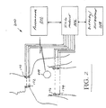
- Fig. 1 illustrates an exemplary ICG module and pacemaker programmer configuration 200. Specifically, the user initiates an optimization routine (such as by choosing a particular programmer command on the programmer device 202).
- This optimization routine causes the programmer device to automatically program a first value (or set of values) into the pacemaker 204, and then obtain measurement(s) of stroke volume via the ICG module 206. Then, a second value or set of values is programmed into the pacemaker 204, a second SV measurement obtained, and so forth, until a desired number of values have been inserted and corresponding SV measurements obtained.
- the ICG module 206 stimulates with constant current, measures resulting voltage, and analyzes ICG waveform to determine ICG stroke volume and/or another ICG optimization variable.
- the ICG module 206 determines the setting that produced the most optimal case of the ICG optimization variable.
- the phrase "most optimal case” is used generally to refer to any situation or series of events which are used as the basis for evaluating the sufficiency of tuning of the stimulation device.
- optimization may comprise the maximal value of stroke volume. Alternatively, if mitral regurgitation was being monitored, the lowest value would be optimal.
- more sophisticated analysis or processing of the data may be used, such as where a plurality of data points (e.g., SV values collected over a given interval of time) are analyzed to determine statistical mean/median values, these derived statistical values being used directly or indirectly as the basis for evaluation.
- a plurality of data points e.g., SV values collected over a given interval of time
- ⁇ standard deviation
- ⁇ 2 variance
- the ICG module 206 is programmed to (i) collect SV, etc. data associated with a first programmed setting, (ii) revise the setting(s) and measure the optimization parameters) again, and (iii) compare the values for the optimization parameter associated with the revised setting to that associated with the prior settings, and selectively retain or discard the new settings.
- the second setting would be retained in a storage area (and the first discarded) since the second setting produced a higher magnitude of stroke volume.
- the third setting(s) would be retained and the second (set) discarded.
- the third setting(s) would be discarded, and the second retained for ultimate comparison to a fourth value, and so forth.
- the pacemaker setting(s) producing higher values of the optimization parameter are retained, in effect "ratcheting" upward until the maximum value is reached. This approach ostensibly may reduce processing overhead and lag, since the optimization (comparative) computations are being performed concurrent with the setting iteration and ICG measurement process.
- variation in the one or more stimulation device parameters need not be sequential, uniform, or of constant direction, although each of the foregoing clearly may be used.
- a first pacemaker value e.g., AV delay
- AV delay AV delay
- a non-constant amount or percentage may be used, such as when "fine tuning" using small increments of variation to find the optimal value after a more coarse evaluation has been conducted.
- a high/low approach may be used, wherein the value of the pacemaker parameter is varied in a first direction (e.g., an increase over the starting value), and then in a second direction (decrease compared to starting value), then a subsequent second increase, and so forth.
- a first parameter may be varied according to any of the foregoing schemes, and then a second parameter varied according to the same or different scheme, which may then be followed by another optimization of the first parameter, and so forth.
- the present invention is in no way limited to any particular method or scheme for parameter variation and cardiac function measurement.
- ambiguity resolution is performed by evaluating a second parameter of interest. For example, if one of two values of W skew produces a higher IVCT (with identical stroke volume), the other value resulting in the lower heart rate may be chosen as being optimal. As another alternative, one such value may produce greater mitral regurgitation, and therefore be less optimal.
- the presence of an ambiguity is used to generate a signal alerting the user/operator as to the presence of the ambiguity (as well as, optionally, other pertinent information), the user/operator then utilizing their expertise or an expert system to select the appropriate parameter value(s).
- the optimization process may be conducted with significant delay and/or at a remote processing facility.
- the optimization may be performed on data streamed from the ICG module via a network interface (e.g., LAN, WAN, MAN, internet, hybrid fiber coax (HFC) w/ DOCSIS modem, etc.) to a remote processing node.
- a network interface e.g., LAN, WAN, MAN, internet, hybrid fiber coax (HFC) w/ DOCSIS modem, etc.
- the streamed data is analyzed in light of historical data relating to the individual subject being evaluated, so as to place the current monitoring/evaluation session in the larger context of that subject's entire monitored history.
- the remote processing may access data for other subjects; e.g., those having similar physiologic conditions, so that that the streamed data can be evaluated against norms or averages of larger populations, or against the data of another specific subject (or group of subjects, such as all patients in the database who have the same height, weight, and age, etc.).
- the streamed data may also be added to these historical databases. if desired.
- This "remote processing" approach has the advantage of allowing each remote processing station (i.e., ICG module and associated pacemaker programmer) to be quite "thin" in terms of software and database overhead, since each can readily access a large repository of relevant data without having to maintain it on-site.
- the results may be returned to the monitoring site (via the same network connection) to complete the tuning process.
- the remote site can signal the local monitoring site to insert a default set of pacemaker values during the interim period, thereby maintaining the subject in a stable physiologic condition until optimal pacemaker values are identified.
- the ICG module 206 transmits this parameter to the pacemaker programming device 202 (or otherwise causes these values to be adopted by the pacemaker 204, such as from pacemaker on-board storage).
- the pacemaker 204 is then operated using the optimal settings until further tuning, if any, is required.
- Fig. 2 shows a wired data connection between the ICG module 206 and the programmer device 202 (i.e., a USB, RS-232, IEEE-1394 "Firewire", or comparable data port arrangement with a physical cable disposed between the devices), it is recognized that the data interface between these devices may be wireless as well, for example those commonly available and employing any number of communication protocols and frequency ranges including without limitation IEEE Std. 802.11, Bluetooth 2.4 GHz, Wireless Medical Telemetry Service (WMTS) medical band (608-614 MHz), 900 MHz or 2.4 GHz ISM bands, 5 GHz band, TM-UWB, and IrDA.
- WMTS Wireless Medical Telemetry Service
- Such functionality may be contained in the form of a GUI generated on display (e.g., by clicking on an icon, selecting a menu entry, selecting a sensitized area of a capacitive or touch screen having programmable "soft" function keys or SFKs, etc.) associated with the programmer device 202 or even a remote display/GUI device 208, or in the form of hardware/firmware as in a fixed function key (FFK).
- a GUI generated on display
- the user interface may be aural, such as in the form of a speech recognition system adapted to recognize the user's verbal commands and initiate the procedure.
- the optimization procedure may be made completely automatic, as where upon proper registration of the ICG module 206 and the programmer device 202 (and the pacemaker 204) such as via RF signals or other protocols occurring at connection and/or power-up of the device(s), the optimization procedure is initiated automatically.
- the optimization may be triggered upon the occurrence of a certain event, including for example the expiration of a given period of time from the last optimization, at a given time/date, upon detection of a certain artifact or waveform present in physiologic signals, etc. All such initiation/control functions are readily implemented by those of ordinary skill in the electronic and programming arts, and accordingly not described further herein.
- optimization algorithm previously described may be disposed entirely or at least partly within the ICG module 206 as opposed to the programmer device 202.
- an SFK or FFK on the module may be used to initiate running of the algorithm on the ICG processor (not shown), with communication between the ICG module and the programmer being conducted
- the ICG module and pacemaker programmer device of the present embodiment do not transmit/receive concurrently (in effect being slotted according to a simple TDMA scheme), as the ICG and programmer carrier frequencies are often near each other (e.g., approximately 70 kHz vs. 100 kHz, respectively).
- the ICG and programmer carrier frequencies are often near each other (e.g., approximately 70 kHz vs. 100 kHz, respectively).
- spectral access and air interface schemes may be employed consistent with the invention to effectuate communications between the pacemaker 204 and the programmer device 202 without interference to the 70 kHz signals of the ICG module 206.
- a direct sequence spread spectrum (DSSS) system is used with a pn (pseudo-noise) spreading code.
- an FHSS system with pseudorandom hop sequence is used.
- an FDMA (“narrowband”) approach is used, with GMSK "upshift” and “downshift” modulation used to encode data.
- GMSK “upshift” and “downshift” modulation used to encode data.
- TM-UWB time-modulated ultra-wide bandwidth
- Fig. 3 illustrates another exemplary embodiment of the apparatus, wherein the aforementioned ICG module and pacemaker programmer device are physically integrated into a single device.
- a standalone box 301 with programmer wand 302 and ICG module 306 are is provided, with communications between the programmer 303 and ICG module 306 being conducted internal to the box 301, thereby obviating the need for the aforementioned wired or wireless interfaces between the separate devices.
- Such internal communications may be effectuated using any number of techniques well known in the computer and electronic arts, including for example use of a PCI or cPCI bus architecture, RapidIO configuration, interprocessor communications, etc., which accordingly are not described further herein.
- the ICG functionality and processing are disposed within an existing pacemaker programmer housing structure (not shown), such as through the addition of an ICG card into the chassis of the programmer device.
- the programmer functionality may be disposed within the ICG module via a peripheral.
- the programmer device may be embodied as a wireless "dongle" of the type well known in the data networking arts which mates with an existing port on the ICG modules, such as an RS-232, USB, IEEE Std. 1394, etc. interface. Common integrated or stand-alone monitor, display, and input devices may also be used. Many other possible physical manifestations of the invention are possible; hence, the present invention should in no way be considered limited to the exemplary embodiment described herein.
- the system e.g., the ICG module 206, 306 is configured to provide the operator with a graphical representation of the analysis performed during optimization.
- the relevant parameter associated with the ICG measurement and used as the basis for optimization e.g., stroke volume
- the selected stimulation device parameter e.g., AV delay, VV skew
- Such graphical representation may comprise any number of well known display formats, such as bar, line, histogram, 3-D, contour, scatter plot, etc., as desired by the user.
- the graphical representation allows the operator to visualize the relationship(s) between ICG measurements and changes in pacemaker programming.
- the user is also provided with a second graphical representation (e.g., icon, illumination, flashing signal, etc.) which indicates the optimal pacemaker setting, and the ability to accept or reject this setting in a "one button" context (thereby also inserting this setting into the pacemaker via the programming device).
- a second graphical representation e.g., icon, illumination, flashing signal, etc.
- the system sequences through a series of AV/VV settings while measuring SV of the subject's heart; the various AV/VV parameter value(s) are displayed for the user (with or without the corresponding SV values), with the best or optimal pacemaker settings (i.e., those which produce the maximal SV) being annotated or highlighted for the user.
- the user then merely invokes acceptance or rejection of the "maximal" parameters, such as via a SFK, FFK, pull-down menu, audible voice command, or other user interface mechanism, at which point the system programs these settings into the pacemaker.
- the ICG module 206, 306 of the present invention may also contain any number of different features to provide enhanced ICG functionality and accuracy, including for example the use of ICG electrodes with predetermined spacing as described in co-pending U.S. Application Serial No. 09/613,183, now U.S. Patent No. 6,636,754 issued October 21, 2003, previously referenced herein.
- the automated selection of optimum ECG lead configuration as described in U.S. Application Serial No. 09/903,473 filed July 10, 2001 and entitled "Apparatus and Method for Determining Cardiac Output in a Living Subject", now U.S. Patent No. 6,602,201 issued August 5, 2003, incorporated herein by reference in its entirety, may also be used.
- Pacing spike detection in the aforementioned patent incorporates some aspects of artificial intelligence, in that it is desirable to detect spikes of varying amplitude, with variable time delays between the A and V spikes, in the presence of noise also having a variable amplitude.
- This is accomplished using a golden section search optimization technique, in conjunction with a fuzzy model.
- the golden section search identifies spikes or other artifacts based primarily on their shape as opposed to amplitude or other criteria, thereby significantly increasing the robustness of the detection algorithm.
- a fuzzy model is used to calculate the noise threshold, in that a pacemaker spike must be distinguishable from its surrounding noise. Because the spike and noise amplitudes vary with each subject, the noise threshold is calculated in one embodiment during the beginning of a monitoring session, or immediately after a lead change.
- This noise threshold is then used as an input to the AV spike detector.
- Table 1 below provides a summarization of the exemplary parameters related to pacing spike detection and cardiac output determination.
- a Reference to right atrium B Sample signifying initial aortic valve opening.
- ECG Electrocardiogram k Discrete time sample
- Q Sample signifying initial left ventricular depolarization
- X Sample signifying aortic valve closure
- the ECG fiducial point detection may also optionally be optimized for arrhythmia detection (described in co-pending application Serial No. 10/393,544 filed January 17, 2001 and entitled “Apparatus and Method for Defibrillation of a Living Subject", also incorporated herein by reference in its entirety) may be used.
- the 10/393,544 application describes an approach for determination of shockable and nonshockable rhythms, including VT and SVT, determining if significant and pulsatile cardiac output (blood flow through the heart) is present with each heartbeat.
- Pacing spike detection is implemented to prevent misclassification of pacing spikes as R points.
- a wavelet algorithm for efficient R point detection during arrhythmias is also used in conjunction with the foregoing.
- a wavelet transform is a time-scale representation of an input signal that is obtained by filtering the signal with a wavelet or scaling function at a particular scale.
- Various wavelets and scaling functions are utilized as part of the invention to emphasize certain features of interest associated with the input impedance and/or ECG waveforms obtained from electrodes positioned on the subject's thorax.
- the resulting emphasized feature in each wavelet transform is then detected to obtain a fiducial point (e.g., B, C, X for the impedance waveform, and R for the ECG waveform).
- this wavelet method is more resistant to noise artifact than empirical waveform processing in the time domain.
- ECG and ICG waveforms are acquired from the hardware, with subsequent software processing performed to analyze and extract the desired information.
- the method of the present embodiment comprises first obtaining signals from the subject containing information relating to the cardiac function of the subject. Next, these signals are analyzed in terms of multiple parameters. Information generated by this analysis is then used as input to a decision process or used for other purposes.
- the ECG is first analyzed for pacing spikes or R points. If pacing spikes are detected, then the ⁇ Z and dZ/dt waveforms are parsed into individual beats according to a first criterion. In one variant, parsing into individual beats of ⁇ Z and dZ/dt occurs based on the pacing spikes. If pacing spikes are not detected, then the ⁇ Z waveforms are parsed according to a second criterion, such as for example detected R points. Within each beat, a plurality of fiducial points (e.g., two), such as the B (aortic valve opening) and X (aortic valve closing) points, are determined.
- fiducial points e.g., two
- the standard deviations of the fiducial point sample locations are calculated. These standard deviations are input to a decision process; when the standard deviations meet certain criteria (such as, for example, the values of the standard deviations being sufficiently large in magnitude), the heart may be unable to pump blood in a coordinated fashion, as the aortic valve openings and closures are highly variable.
- the ECG waveform obtained from the subject (or intermediary device) is processed in the ECG "module” to detect artifacts.
- the term “module” may comprise a physical device or component within the ICG module, or alternatively a “virtual” module, such as in the case of where the signal processing performed by the module is distributed across a number of different components or software processes, and/or distributed temporally.
- the term module should in no way be considered limiting with respect to any particular configuration, arrangement, or sequence.
- One such exemplary artifact detected by the ECG module comprises pacing spikes, with detection according to the methodologies set forth in co-owned and co-pending U.S. patent application Serial No. 10/329,129 filed December 24, 2002 and entitled "Method and Apparatus for Waveform Assessment", previously incorporated herein. Specifically, if one or more (e.g., two) pacing spikes are present between QRS complexes, the most recent spike is used to parse the next beats of ⁇ Z and dZ/dt. The parsed ⁇ Z and dZ/dt beats are transmitted for further processing. If a spike is not present, then R point detection is conducted, with the detected R point used to parse the next beats.
- R point detection methodology is adapted in four (4) aspects.
- a first threshold such as for example 10% of the max value of the preceding 300 samples
- a second threshold such as for example 27.5% of the previous QRS complex amplitude in the wavelet test value signal
- the larger of the two values is used for beat detection, although it will be recognized that more sophisticated analytical methods relating to the two (or more) thresholds may be implemented, such methods being readily implemented by those of ordinary skill provided the present disclosure.
- the maximum value window for detection of a QRS complex is set at 40 samples. This number may be varied, however, based on the desired application and other factors.
- the instant embodiment first isolates the R point in the wavelet test value signal in a sample "window" (e.g., 50 samples) around the QRS complex location. Once this isolation is performed, the maximum absolute value of the ECG in another sample window (e.g., 7 samples) around this point is marked as the R point.
- a sample "window" e.g., 50 samples
- the maximum absolute value of the ECG in another sample window e.g., 7 samples
- the next sample to begin looking for a QRS complex location is set to the falling edge of the QRS complex window.
- This is the first sample that is less than the maximum value of the wavelet test value window that contains the QRS complex.
- the WT_max signal (the signal having the maximum value of the previous 40 samples) is used to establish an upper bound. This in effect generates a "box" in the signal around a QRS complex, where the left-hand corner of the box comprises the QRS complex location.
- the search for another QRS complex is performed. This first smaller magnitude sample is referred to as the "falling edge", because the signal starts declining towards 0 until the baseline between beats is reached.
- the following parameters are also specified in the exemplary embodiment:
- x ( k ) is the sample number to begin looking for next QRS complex.
- ICG (and ECG) signal processing set forth herein is described primarily in terms of software algorithms, performance of at least portions of these analysis may be performed in hardware or firmware, such as for example in preconfigured logic gates (e.g., FPGAs or ASICs) or DSP front-end or back-end analog processing.
- preconfigured logic gates e.g., FPGAs or ASICs
- DSP front-end or back-end analog processing e.g., DSP front-end or back-end analog processing.
- the present invention should therefore not be considered to be limited to software-based processing.
Landscapes
- Health & Medical Sciences (AREA)
- Life Sciences & Earth Sciences (AREA)
- Public Health (AREA)
- Veterinary Medicine (AREA)
- Radiology & Medical Imaging (AREA)
- Biomedical Technology (AREA)
- Animal Behavior & Ethology (AREA)
- General Health & Medical Sciences (AREA)
- Engineering & Computer Science (AREA)
- Nuclear Medicine, Radiotherapy & Molecular Imaging (AREA)
- Heart & Thoracic Surgery (AREA)
- Biophysics (AREA)
- Cardiology (AREA)
- Physiology (AREA)
- Electrotherapy Devices (AREA)
- Finger-Pressure Massage (AREA)
Applications Claiming Priority (2)
| Application Number | Priority Date | Filing Date | Title |
|---|---|---|---|
| US10/453,820 US20040243192A1 (en) | 2003-06-02 | 2003-06-02 | Physiologic stimulator tuning apparatus and method |
| US453820 | 2003-06-02 |
Publications (2)
| Publication Number | Publication Date |
|---|---|
| EP1484083A1 true EP1484083A1 (fr) | 2004-12-08 |
| EP1484083B1 EP1484083B1 (fr) | 2007-05-23 |
Family
ID=33159529
Family Applications (1)
| Application Number | Title | Priority Date | Filing Date |
|---|---|---|---|
| EP04253249A Expired - Lifetime EP1484083B1 (fr) | 2003-06-02 | 2004-06-01 | Appareil de réglage de stimulateur physiologique |
Country Status (4)
| Country | Link |
|---|---|
| US (1) | US20040243192A1 (fr) |
| EP (1) | EP1484083B1 (fr) |
| AT (1) | ATE362780T1 (fr) |
| DE (1) | DE602004006561D1 (fr) |
Cited By (6)
| Publication number | Priority date | Publication date | Assignee | Title |
|---|---|---|---|---|
| EP1862195A1 (fr) * | 2006-06-02 | 2007-12-05 | Ela Medical | Dispositif médical actif tel qu'implant actif ou programmateur pour un tel implant, comprenant des moyens de télémétrie RF |
| WO2008079347A1 (fr) * | 2006-12-21 | 2008-07-03 | Cardiac Pacemakers, Inc. | Dispositif implantable avec plusieurs ensembles de paramètres |
| WO2010024733A1 (fr) | 2008-08-28 | 2010-03-04 | St. Jude Medical Ab | Dispositif médical implantable et procédé de détermination d’un paramètre de performance du myocarde |
| US8768466B2 (en) | 2007-10-12 | 2014-07-01 | Cardiac Pacemakers, Inc. | Method and apparatus to trend and optimize an implantable medical device using a patient management system |
| US8868183B2 (en) | 2006-12-21 | 2014-10-21 | Cardiac Pacemakers, Inc. | Method and apparatus to implement multiple parameter sets in an implantable device |
| WO2017192301A1 (fr) * | 2016-05-03 | 2017-11-09 | Cardioinsight Technologies, Inc. | Détection et analyse de formes d'onde cardiaques |
Families Citing this family (44)
| Publication number | Priority date | Publication date | Assignee | Title |
|---|---|---|---|---|
| US7972275B2 (en) | 2002-12-30 | 2011-07-05 | Cardiac Pacemakers, Inc. | Method and apparatus for monitoring of diastolic hemodynamics |
| FR2851860B1 (fr) * | 2003-02-28 | 2005-04-15 | Suisse Electronique Microtech | Procede d'attenuation de l'influence d'interferences produites par des systemes de transmission radio en rafales sur des communications uwb |
| US7065400B2 (en) * | 2003-08-20 | 2006-06-20 | Pacesetter, Inc. | Method and apparatus for automatically programming CRT devices |
| US7592909B2 (en) * | 2006-01-19 | 2009-09-22 | Board Of Regents, The University Of Texas System | Location and tracking system using wireless technology |
| US7010347B2 (en) * | 2004-02-14 | 2006-03-07 | Pacesetter, Inc. | Optimization of impedance signals for closed loop programming of cardiac resynchronization therapy devices |
| US20070191901A1 (en) * | 2004-06-04 | 2007-08-16 | Pacesetter, Inc. | Quantifying systolic and diastolic cardiac performance from dynamic impedance waveforms |
| US7925329B2 (en) * | 2004-10-08 | 2011-04-12 | Proteus Biomedical, Inc. | Implantable doppler tomography system |
| WO2006042039A2 (fr) * | 2004-10-08 | 2006-04-20 | Proteus Biomedical, Inc. | Tomographies a champ en continu |
| US20080058656A1 (en) * | 2004-10-08 | 2008-03-06 | Costello Benedict J | Electric tomography |
| US7406351B2 (en) | 2005-04-28 | 2008-07-29 | Medtronic, Inc. | Activity sensing for stimulator control |
| WO2006119015A1 (fr) | 2005-04-30 | 2006-11-09 | Medtronic, Inc. | Ajustement de stimulation sur la base d'une impedance |
| US7922669B2 (en) | 2005-06-08 | 2011-04-12 | Cardiac Pacemakers, Inc. | Ischemia detection using a heart sound sensor |
| US20110066057A1 (en) * | 2005-10-31 | 2011-03-17 | Zdeblick Mark J | Electrical Angle Gauge |
| US20070167758A1 (en) * | 2005-11-23 | 2007-07-19 | Costello Benedict J | Automated detection of cardiac motion using contrast markers |
| US8108034B2 (en) * | 2005-11-28 | 2012-01-31 | Cardiac Pacemakers, Inc. | Systems and methods for valvular regurgitation detection |
| US20070161894A1 (en) * | 2005-12-23 | 2007-07-12 | Mark Zdeblick | Ultrasound synchrony measurement |
| US20080208068A1 (en) * | 2007-02-26 | 2008-08-28 | Timothy Robertson | Dynamic positional information constrained heart model |
| US8290577B2 (en) * | 2007-03-23 | 2012-10-16 | Brooks Donald J | Methods and apparatus for enhanced fiducial point determination and non-invasive hemodynamic parameter determination |
| US8718773B2 (en) | 2007-05-23 | 2014-05-06 | Ebr Systems, Inc. | Optimizing energy transmission in a leadless tissue stimulation system |
| WO2009009746A1 (fr) * | 2007-07-11 | 2009-01-15 | Proteus Biomedical, Inc. | Tomographie électrique à spectre étalé |
| US8972007B2 (en) * | 2007-09-25 | 2015-03-03 | Cardiac Pacemakers, Inc. | Variable shortening of AV delay for treatment of cardiac disease |
| US7953493B2 (en) | 2007-12-27 | 2011-05-31 | Ebr Systems, Inc. | Optimizing size of implantable medical devices by isolating the power source |
| WO2009120636A1 (fr) | 2008-03-25 | 2009-10-01 | Ebr Systems, Inc. | Connexion d’électrode temporaire pour des systèmes de stimulation sans fil |
| US20100280366A1 (en) * | 2008-05-13 | 2010-11-04 | Lawrence Arne | Continuous field tomography systems and methods of using the same |
| WO2009158601A2 (fr) * | 2008-06-27 | 2009-12-30 | Proteus Biomedical, Inc. | Applications cliniques pour ensembles de mesures réalisées par tomographie électrique |
| US20100016911A1 (en) | 2008-07-16 | 2010-01-21 | Ebr Systems, Inc. | Local Lead To Improve Energy Efficiency In Implantable Wireless Acoustic Stimulators |
| US7950971B2 (en) * | 2008-08-08 | 2011-05-31 | Cardiodynamics International Corporation | Electrical connector apparatus and methods |
| US11013924B2 (en) | 2008-10-03 | 2021-05-25 | Duke University | Non-regular electrical stimulation patterns for treating neurological disorders |
| US8923981B2 (en) | 2008-10-03 | 2014-12-30 | Duke University | Non-regular electrical stimulation patterns designed with a cost function for treating neurological disorders |
| US8798755B2 (en) | 2008-10-03 | 2014-08-05 | Duke University | Non-regular electrical stimulation patterns for treating neurological disorders |
| US9802046B2 (en) | 2008-10-03 | 2017-10-31 | Duke University | Non-regular electrical stimulation patterns for improved efficiency in treating Parkinson's Disease |
| CA3099328C (fr) | 2008-10-03 | 2023-01-03 | Duke University | Configurations electriquement non regulieres de stimulation pour traitement de troubles neurologiques |
| JP2012510343A (ja) * | 2008-12-02 | 2012-05-10 | プロテウス バイオメディカル インコーポレイテッド | 電気断層撮影における最適な駆動周波数の選択 |
| US8088091B2 (en) * | 2009-03-09 | 2012-01-03 | New Jersey Institute Of Technology | No clog shunt using a compact fluid drag path |
| GB0908506D0 (en) * | 2009-05-18 | 2009-06-24 | Imagination Tech Ltd | Method and apparatus for drawing polygons |
| DE102009031232A1 (de) * | 2009-06-26 | 2010-12-30 | Universitätsklinikum Jena | Verfahren und Vorrichtung zur transthorakalen, transösophagealen und intrakardialen Impedanzkardiographie, insbesondere für die Stimulation und Ablation des Herzens |
| EP3305363A1 (fr) | 2010-05-27 | 2018-04-11 | Ndi Medical, LLC | Formes d'onde pour le traitement de troubles neurologiques optimisés pour l'efficacité énergétique |
| US20120123503A1 (en) * | 2010-11-15 | 2012-05-17 | Medtronic, Inc. | Patient programmer with customizable programming |
| US9050014B2 (en) * | 2011-12-14 | 2015-06-09 | Siemens Medical Solutions Usa, Inc. | System for cardiac arrhythmia detection and characterization |
| US9440076B2 (en) * | 2013-03-15 | 2016-09-13 | Globus Medical, Inc. | Spinal cord stimulator system |
| AU2014268445B2 (en) | 2013-05-22 | 2019-03-07 | Deep Brain Innovations LLC | Deep brain stimulator and method of use |
| US10688306B2 (en) | 2013-12-23 | 2020-06-23 | Deep Brain Innovations LLC | Programming systems for deep brain stimulator system |
| US10226193B2 (en) | 2015-03-31 | 2019-03-12 | Medtronic Ps Medical, Inc. | Wireless pressure measurement and monitoring for shunts |
| US12350497B2 (en) | 2022-02-10 | 2025-07-08 | Ebr Systems, Inc. | Tissue stimulation systems and methods, such as for pacing cardiac tissue |
Citations (5)
| Publication number | Priority date | Publication date | Assignee | Title |
|---|---|---|---|---|
| US4901726A (en) * | 1988-01-29 | 1990-02-20 | Telectronics N.V. | Rate-responsive, distributed-rate pacemaker |
| US5999854A (en) * | 1998-04-14 | 1999-12-07 | Intermedics Inc. | Implantable cardiac stimulator with physiologic sensor based on mechanical-electric phase relation |
| US6055454A (en) * | 1998-07-27 | 2000-04-25 | Cardiac Pacemakers, Inc. | Cardiac pacemaker with automatic response optimization of a physiologic sensor based on a second sensor |
| WO2001024875A1 (fr) * | 1999-10-06 | 2001-04-12 | Cardiac Pacemakers, Inc. | Stimulateur a frequence de stimulation a adaptation automatique au mode de vie |
| US6263243B1 (en) * | 1996-03-04 | 2001-07-17 | Biotronik Mess-Und Therapiegeraete Gmbh & Co. Ingenieurbuero Berlin | Rate adaptive pacemaker |
Family Cites Families (12)
| Publication number | Priority date | Publication date | Assignee | Title |
|---|---|---|---|---|
| US30101A (en) * | 1860-09-18 | Folding-case bedstead | ||
| USRE30101E (en) * | 1964-08-19 | 1979-09-25 | Regents Of The University Of Minnesota | Impedance plethysmograph |
| US6044294A (en) * | 1995-12-15 | 2000-03-28 | Pacesetter, Inc. | Methods and apparatus for measuring impedance in the body |
| US6058325A (en) * | 1996-04-16 | 2000-05-02 | Cardiotronics | Method and apparatus for high current electrode, transthoracic and transmyocardial impedance estimation |
| US5891178A (en) * | 1996-05-14 | 1999-04-06 | Pacesetter, Inc. | Programmer system and associated methods for rapidly evaluating and programming an implanted cardiac device |
| US5782884A (en) * | 1996-11-05 | 1998-07-21 | Sulzer Intermedics Inc. | Rate responsive cardiac pacemaker with peak impedance detection for rate control |
| US6186955B1 (en) * | 1998-11-16 | 2001-02-13 | Gail D. Baura | Noninvasive continuous cardiac output monitor |
| US6190324B1 (en) * | 1999-04-28 | 2001-02-20 | Medtronic, Inc. | Implantable medical device for tracking patient cardiac status |
| US6561989B2 (en) * | 2000-07-10 | 2003-05-13 | Bayer Healthcare, Llc | Thin lance and test sensor having same |
| US6636754B1 (en) * | 2000-07-10 | 2003-10-21 | Cardiodynamics International Corporation | Apparatus and method for determining cardiac output in a living subject |
| US6602201B1 (en) * | 2000-07-10 | 2003-08-05 | Cardiodynamics International Corporation | Apparatus and method for determining cardiac output in a living subject |
| EP1350539B1 (fr) * | 2002-04-03 | 2006-10-18 | Osypka Medical GmbH | Appareil pour la détermination automatique de valeurs paramétriques hémodynamiquement optimales de stimulation cardiaque |
-
2003
- 2003-06-02 US US10/453,820 patent/US20040243192A1/en not_active Abandoned
-
2004
- 2004-06-01 DE DE602004006561T patent/DE602004006561D1/de not_active Expired - Lifetime
- 2004-06-01 EP EP04253249A patent/EP1484083B1/fr not_active Expired - Lifetime
- 2004-06-01 AT AT04253249T patent/ATE362780T1/de not_active IP Right Cessation
Patent Citations (5)
| Publication number | Priority date | Publication date | Assignee | Title |
|---|---|---|---|---|
| US4901726A (en) * | 1988-01-29 | 1990-02-20 | Telectronics N.V. | Rate-responsive, distributed-rate pacemaker |
| US6263243B1 (en) * | 1996-03-04 | 2001-07-17 | Biotronik Mess-Und Therapiegeraete Gmbh & Co. Ingenieurbuero Berlin | Rate adaptive pacemaker |
| US5999854A (en) * | 1998-04-14 | 1999-12-07 | Intermedics Inc. | Implantable cardiac stimulator with physiologic sensor based on mechanical-electric phase relation |
| US6055454A (en) * | 1998-07-27 | 2000-04-25 | Cardiac Pacemakers, Inc. | Cardiac pacemaker with automatic response optimization of a physiologic sensor based on a second sensor |
| WO2001024875A1 (fr) * | 1999-10-06 | 2001-04-12 | Cardiac Pacemakers, Inc. | Stimulateur a frequence de stimulation a adaptation automatique au mode de vie |
Cited By (11)
| Publication number | Priority date | Publication date | Assignee | Title |
|---|---|---|---|---|
| EP1862195A1 (fr) * | 2006-06-02 | 2007-12-05 | Ela Medical | Dispositif médical actif tel qu'implant actif ou programmateur pour un tel implant, comprenant des moyens de télémétrie RF |
| WO2008079347A1 (fr) * | 2006-12-21 | 2008-07-03 | Cardiac Pacemakers, Inc. | Dispositif implantable avec plusieurs ensembles de paramètres |
| US8868183B2 (en) | 2006-12-21 | 2014-10-21 | Cardiac Pacemakers, Inc. | Method and apparatus to implement multiple parameter sets in an implantable device |
| US8768466B2 (en) | 2007-10-12 | 2014-07-01 | Cardiac Pacemakers, Inc. | Method and apparatus to trend and optimize an implantable medical device using a patient management system |
| WO2010024733A1 (fr) | 2008-08-28 | 2010-03-04 | St. Jude Medical Ab | Dispositif médical implantable et procédé de détermination d’un paramètre de performance du myocarde |
| EP2318096A4 (fr) * | 2008-08-28 | 2013-01-02 | St Jude Medical | Dispositif médical implantable et procédé de détermination d'un paramètre de performance du myocarde |
| US9241653B2 (en) | 2008-08-28 | 2016-01-26 | St. Jude Medical Ab | Method and device for estimating a myocardial performance parameter |
| US9549674B2 (en) | 2008-08-28 | 2017-01-24 | St. Jude Medical Ab | Method and device for estimating a myocardial performance parameter |
| WO2017192301A1 (fr) * | 2016-05-03 | 2017-11-09 | Cardioinsight Technologies, Inc. | Détection et analyse de formes d'onde cardiaques |
| CN109069049A (zh) * | 2016-05-03 | 2018-12-21 | 科迪影技术股份有限公司 | 心脏波形的检测和分析 |
| US10376173B2 (en) | 2016-05-03 | 2019-08-13 | Cardioinsight Technologies, Inc. | Detection and analysis of cardiac waveforms |
Also Published As
| Publication number | Publication date |
|---|---|
| EP1484083B1 (fr) | 2007-05-23 |
| DE602004006561D1 (de) | 2007-07-05 |
| ATE362780T1 (de) | 2007-06-15 |
| US20040243192A1 (en) | 2004-12-02 |
Similar Documents
| Publication | Publication Date | Title |
|---|---|---|
| EP1484083B1 (fr) | Appareil de réglage de stimulateur physiologique | |
| CN111225716B (zh) | 阻抗感测 | |
| US9119547B2 (en) | Arrhythmia discrimination based on determination of rate dependency | |
| US5458623A (en) | Automatic atrial pacing threshold determination utilizing an external programmer and a surface electrogram | |
| US7941205B2 (en) | System and method for separating cardiac signals | |
| US7751873B2 (en) | Wavelet based feature extraction and dimension reduction for the classification of human cardiac electrogram depolarization waveforms | |
| US8617082B2 (en) | Heart sounds-based pacing optimization | |
| US9320448B2 (en) | Systems and methods for improved atrial fibrillation (AF) monitoring | |
| US8583228B2 (en) | Automatic multi-level therapy based on morphologic organization of an arrhythmia | |
| US8055333B2 (en) | Device and method for detecting cardiac impairments | |
| US7933651B2 (en) | Cardiac template generation based on patient response information | |
| US20250276186A1 (en) | Systems and methods for improved his bundle and backup pacing timing | |
| US20080228093A1 (en) | Systems and methods for enhancing cardiac signal features used in morphology discrimination | |
| US12161475B2 (en) | State-based atrial event detection | |
| JP2007500550A (ja) | 心臓再同期療法の最適化方法 | |
| US20200353249A1 (en) | Frequency domain-based methods for his bundle capture classification | |
| US20120108994A1 (en) | Morphology change detection for cardiac signal analysis | |
| US7664547B2 (en) | Active implantable medical device with biventricular pacing and automatic optimization of pacing configuration | |
| US20250381407A1 (en) | Method and system for processing heart sound signals in an implantable medical device | |
| EP4699543A1 (fr) | Procédés et systèmes d'utilisation d'un algorithme basé sur une sismocardiographie pour surveiller le fonctionnement d'une valvule cardiaque | |
| US20220167903A1 (en) | Methods and systems to manage presentation of representative cardiac activity segments for clusters of such segments | |
| Augustynek et al. | An artificial heart system for testing and evaluation of cardiac pacemakers | |
| CN115591120A (zh) | 用于优化可植入医疗设备的滤波器设置的方法和系统 | |
| CN117042681A (zh) | 用于心脏监测的间接感测机构 |
Legal Events
| Date | Code | Title | Description |
|---|---|---|---|
| PUAI | Public reference made under article 153(3) epc to a published international application that has entered the european phase |
Free format text: ORIGINAL CODE: 0009012 |
|
| 17P | Request for examination filed |
Effective date: 20040612 |
|
| AK | Designated contracting states |
Kind code of ref document: A1 Designated state(s): AT BE BG CH CY CZ DE DK EE ES FI FR GB GR HU IE IT LI LU MC NL PL PT RO SE SI SK TR |
|
| AX | Request for extension of the european patent |
Extension state: AL HR LT LV MK |
|
| 17Q | First examination report despatched |
Effective date: 20050614 |
|
| AKX | Designation fees paid |
Designated state(s): AT BE BG CH CY CZ DE DK EE ES FI FR GB GR HU IE IT LI LU MC NL PL PT RO SE SI SK TR |
|
| RTI1 | Title (correction) |
Free format text: PHYSIOLOGIC STIMULATOR TUNING APPARATUS |
|
| GRAP | Despatch of communication of intention to grant a patent |
Free format text: ORIGINAL CODE: EPIDOSNIGR1 |
|
| GRAS | Grant fee paid |
Free format text: ORIGINAL CODE: EPIDOSNIGR3 |
|
| GRAA | (expected) grant |
Free format text: ORIGINAL CODE: 0009210 |
|
| AK | Designated contracting states |
Kind code of ref document: B1 Designated state(s): AT BE BG CH CY CZ DE DK EE ES FI FR GB GR HU IE IT LI LU MC NL PL PT RO SE SI SK TR |
|
| PG25 | Lapsed in a contracting state [announced via postgrant information from national office to epo] |
Ref country code: LI Free format text: LAPSE BECAUSE OF FAILURE TO SUBMIT A TRANSLATION OF THE DESCRIPTION OR TO PAY THE FEE WITHIN THE PRESCRIBED TIME-LIMIT Effective date: 20070523 Ref country code: FI Free format text: LAPSE BECAUSE OF FAILURE TO SUBMIT A TRANSLATION OF THE DESCRIPTION OR TO PAY THE FEE WITHIN THE PRESCRIBED TIME-LIMIT Effective date: 20070523 Ref country code: CH Free format text: LAPSE BECAUSE OF FAILURE TO SUBMIT A TRANSLATION OF THE DESCRIPTION OR TO PAY THE FEE WITHIN THE PRESCRIBED TIME-LIMIT Effective date: 20070523 |
|
| REG | Reference to a national code |
Ref country code: GB Ref legal event code: FG4D |
|
| REG | Reference to a national code |
Ref country code: CH Ref legal event code: EP |
|
| REG | Reference to a national code |
Ref country code: IE Ref legal event code: FG4D |
|
| REF | Corresponds to: |
Ref document number: 602004006561 Country of ref document: DE Date of ref document: 20070705 Kind code of ref document: P |
|
| PG25 | Lapsed in a contracting state [announced via postgrant information from national office to epo] |
Ref country code: SE Free format text: LAPSE BECAUSE OF FAILURE TO SUBMIT A TRANSLATION OF THE DESCRIPTION OR TO PAY THE FEE WITHIN THE PRESCRIBED TIME-LIMIT Effective date: 20070823 |
|
| PG25 | Lapsed in a contracting state [announced via postgrant information from national office to epo] |
Ref country code: ES Free format text: LAPSE BECAUSE OF FAILURE TO SUBMIT A TRANSLATION OF THE DESCRIPTION OR TO PAY THE FEE WITHIN THE PRESCRIBED TIME-LIMIT Effective date: 20070903 |
|
| NLV1 | Nl: lapsed or annulled due to failure to fulfill the requirements of art. 29p and 29m of the patents act | ||
| PG25 | Lapsed in a contracting state [announced via postgrant information from national office to epo] |
Ref country code: PL Free format text: LAPSE BECAUSE OF FAILURE TO SUBMIT A TRANSLATION OF THE DESCRIPTION OR TO PAY THE FEE WITHIN THE PRESCRIBED TIME-LIMIT Effective date: 20070523 Ref country code: AT Free format text: LAPSE BECAUSE OF FAILURE TO SUBMIT A TRANSLATION OF THE DESCRIPTION OR TO PAY THE FEE WITHIN THE PRESCRIBED TIME-LIMIT Effective date: 20070523 |
|
| REG | Reference to a national code |
Ref country code: CH Ref legal event code: PL |
|
| PG25 | Lapsed in a contracting state [announced via postgrant information from national office to epo] |
Ref country code: BE Free format text: LAPSE BECAUSE OF FAILURE TO SUBMIT A TRANSLATION OF THE DESCRIPTION OR TO PAY THE FEE WITHIN THE PRESCRIBED TIME-LIMIT Effective date: 20070523 |
|
| EN | Fr: translation not filed | ||
| PG25 | Lapsed in a contracting state [announced via postgrant information from national office to epo] |
Ref country code: PT Free format text: LAPSE BECAUSE OF FAILURE TO SUBMIT A TRANSLATION OF THE DESCRIPTION OR TO PAY THE FEE WITHIN THE PRESCRIBED TIME-LIMIT Effective date: 20071023 Ref country code: BG Free format text: LAPSE BECAUSE OF FAILURE TO SUBMIT A TRANSLATION OF THE DESCRIPTION OR TO PAY THE FEE WITHIN THE PRESCRIBED TIME-LIMIT Effective date: 20070823 Ref country code: MC Free format text: LAPSE BECAUSE OF NON-PAYMENT OF DUE FEES Effective date: 20070630 Ref country code: CZ Free format text: LAPSE BECAUSE OF FAILURE TO SUBMIT A TRANSLATION OF THE DESCRIPTION OR TO PAY THE FEE WITHIN THE PRESCRIBED TIME-LIMIT Effective date: 20070523 Ref country code: SI Free format text: LAPSE BECAUSE OF FAILURE TO SUBMIT A TRANSLATION OF THE DESCRIPTION OR TO PAY THE FEE WITHIN THE PRESCRIBED TIME-LIMIT Effective date: 20070523 Ref country code: DK Free format text: LAPSE BECAUSE OF FAILURE TO SUBMIT A TRANSLATION OF THE DESCRIPTION OR TO PAY THE FEE WITHIN THE PRESCRIBED TIME-LIMIT Effective date: 20070523 Ref country code: NL Free format text: LAPSE BECAUSE OF FAILURE TO SUBMIT A TRANSLATION OF THE DESCRIPTION OR TO PAY THE FEE WITHIN THE PRESCRIBED TIME-LIMIT Effective date: 20070523 Ref country code: DE Free format text: LAPSE BECAUSE OF FAILURE TO SUBMIT A TRANSLATION OF THE DESCRIPTION OR TO PAY THE FEE WITHIN THE PRESCRIBED TIME-LIMIT Effective date: 20070823 |
|
| PG25 | Lapsed in a contracting state [announced via postgrant information from national office to epo] |
Ref country code: SK Free format text: LAPSE BECAUSE OF FAILURE TO SUBMIT A TRANSLATION OF THE DESCRIPTION OR TO PAY THE FEE WITHIN THE PRESCRIBED TIME-LIMIT Effective date: 20070523 |
|
| PLBE | No opposition filed within time limit |
Free format text: ORIGINAL CODE: 0009261 |
|
| STAA | Information on the status of an ep patent application or granted ep patent |
Free format text: STATUS: NO OPPOSITION FILED WITHIN TIME LIMIT |
|
| 26N | No opposition filed |
Effective date: 20080226 |
|
| PG25 | Lapsed in a contracting state [announced via postgrant information from national office to epo] |
Ref country code: IT Free format text: LAPSE BECAUSE OF FAILURE TO SUBMIT A TRANSLATION OF THE DESCRIPTION OR TO PAY THE FEE WITHIN THE PRESCRIBED TIME-LIMIT Effective date: 20070523 Ref country code: GR Free format text: LAPSE BECAUSE OF FAILURE TO SUBMIT A TRANSLATION OF THE DESCRIPTION OR TO PAY THE FEE WITHIN THE PRESCRIBED TIME-LIMIT Effective date: 20070824 |
|
| PG25 | Lapsed in a contracting state [announced via postgrant information from national office to epo] |
Ref country code: RO Free format text: LAPSE BECAUSE OF FAILURE TO SUBMIT A TRANSLATION OF THE DESCRIPTION OR TO PAY THE FEE WITHIN THE PRESCRIBED TIME-LIMIT Effective date: 20070523 Ref country code: IE Free format text: LAPSE BECAUSE OF NON-PAYMENT OF DUE FEES Effective date: 20070601 |
|
| PG25 | Lapsed in a contracting state [announced via postgrant information from national office to epo] |
Ref country code: FR Free format text: LAPSE BECAUSE OF FAILURE TO SUBMIT A TRANSLATION OF THE DESCRIPTION OR TO PAY THE FEE WITHIN THE PRESCRIBED TIME-LIMIT Effective date: 20080118 |
|
| PG25 | Lapsed in a contracting state [announced via postgrant information from national office to epo] |
Ref country code: EE Free format text: LAPSE BECAUSE OF FAILURE TO SUBMIT A TRANSLATION OF THE DESCRIPTION OR TO PAY THE FEE WITHIN THE PRESCRIBED TIME-LIMIT Effective date: 20070523 |
|
| PG25 | Lapsed in a contracting state [announced via postgrant information from national office to epo] |
Ref country code: CY Free format text: LAPSE BECAUSE OF FAILURE TO SUBMIT A TRANSLATION OF THE DESCRIPTION OR TO PAY THE FEE WITHIN THE PRESCRIBED TIME-LIMIT Effective date: 20070523 |
|
| PG25 | Lapsed in a contracting state [announced via postgrant information from national office to epo] |
Ref country code: LU Free format text: LAPSE BECAUSE OF NON-PAYMENT OF DUE FEES Effective date: 20070601 |
|
| PG25 | Lapsed in a contracting state [announced via postgrant information from national office to epo] |
Ref country code: TR Free format text: LAPSE BECAUSE OF FAILURE TO SUBMIT A TRANSLATION OF THE DESCRIPTION OR TO PAY THE FEE WITHIN THE PRESCRIBED TIME-LIMIT Effective date: 20070523 Ref country code: HU Free format text: LAPSE BECAUSE OF FAILURE TO SUBMIT A TRANSLATION OF THE DESCRIPTION OR TO PAY THE FEE WITHIN THE PRESCRIBED TIME-LIMIT Effective date: 20071124 |
|
| REG | Reference to a national code |
Ref country code: GB Ref legal event code: 732E Free format text: REGISTERED BETWEEN 20150226 AND 20150304 |
|
| PGFP | Annual fee paid to national office [announced via postgrant information from national office to epo] |
Ref country code: GB Payment date: 20230427 Year of fee payment: 20 |
|
| REG | Reference to a national code |
Ref country code: GB Ref legal event code: PE20 Expiry date: 20240531 |
|
| PG25 | Lapsed in a contracting state [announced via postgrant information from national office to epo] |
Ref country code: GB Free format text: LAPSE BECAUSE OF EXPIRATION OF PROTECTION Effective date: 20240531 |
|
| PG25 | Lapsed in a contracting state [announced via postgrant information from national office to epo] |
Ref country code: GB Free format text: LAPSE BECAUSE OF EXPIRATION OF PROTECTION Effective date: 20240531 |